Motorola CP185 Series Quick Reference Manual
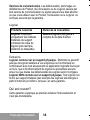
- Catégorie
- Radios bidirectionnelles
- Taper
- Quick Reference Manual

68007024011-A
68007
CP185_QRC_Bilingual_A7.book Page 1 Monday, November 9, 2015 12:17 PM

CP185_QRC_Bilingual_A7.book Page 2 Monday, November 9, 2015 12:17 PM

1
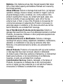
English
Congratulations on your purchase of the CP185
Two-Way Radio.
This is a Quick Reference Guide; for more information
on this radio features please download the full User
Guide from https://motonline.mot.com
or
www.motorola.com/business or call our Customer
Care Service at 1-800-422-4210.
68007024011-A
68007
CP185_QRC_Bilingual_A7.book Page 1 Monday, November 9, 2015 12:17 PM

2
English
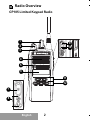
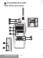
Radio Overview
CP185 Limited Keypad Radio
CP185
1
2
3
5
6
4
9
10
11
12
8
7
CP185_QRC_Bilingual_A7.book Page 2 Monday, November 9, 2015 12:17 PM

3
English
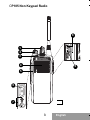
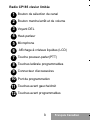
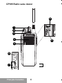
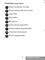
CP185 Non Keypad Radio
1
2
3
5
4
8
9
6
7
CP185_QRC_Bilingual_A7.book Page 3 Monday, November 9, 2015 12:17 PM

4
English
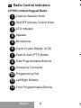
Radio Control Indicators
CP185 Limited Keypad Radio
Channel Selector Knob
ON/OFF/Volume Control Knob
LED Indicator
Speaker
Microphone
Liquid Crystal Display (LCD)
Push-to-Talk (PTT) Button
Side Programmable Buttons
Accessory Connector
Programming Port
Left/Right Buttons
Front Programmable Buttons
1
2
3
4
5
6
7
8
9
10
11
12
CP185_QRC_Bilingual_A7.book Page 4 Monday, November 9, 2015 12:17 PM

5
English
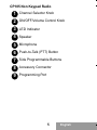
CP185 Non Keypad Radio
Channel Selector Knob
ON/OFF/Volume Control Knob
LED Indicator
Speaker
Microphone
Push-to-Talk (PTT) Button
Side Programmable Buttons
Accessory Connector
Programming Port
1
2
3
4
5
6
7
8
9
CP185_QRC_Bilingual_A7.book Page 5 Monday, November 9, 2015 12:17 PM

6
English
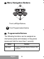
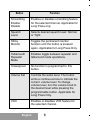
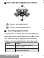
Menu Navigation Buttons
Programmable Buttons
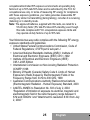
The following functions can be assigned as
short press (press and release) or long press
(press and hold for more than 1 second):
Front Left/Right Buttons
Front Programmable Buttons
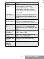
Button Function
Backlight Toggles backlight display between ON
and OFF.
A
B
B
CP185_QRC_Bilingual_A7.book Page 6 Monday, November 9, 2015 12:17 PM

7
English
Channel Alias Toggles display between Channel
Number and Channel Alias.
Button Function
Keypad Lock Locks or unlocks all buttons except
PTT, Side Programmable Button 1 and
Side Programmable Button 2, Channel
Selector Knoband ON/OFF/Volume
Knob. Applicable for Long Press Only.
Monitor Monitors the channel for any activity as
long as the button is pressed.
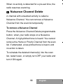
Nuisance
Channel
Delete
Removes unwanted channel(s)
temporarily from scan list during Scan.
Applicable for Long Press Only.
TPL/DPL
Enable
Enables or disables radio from
requiring matching TPL/DPL to
unsquelch.
Power Level Selects required power level: High or
Low.
Reverse
Burst
Select the Reverse Burst Type: None,
180 or 240.
Channel
Scan
Starts or stops Channel Scan.
Scrambling
Code Select
Toggles between the two scrambling
codes available.
CP185_QRC_Bilingual_A7.book Page 7 Monday, November 9, 2015 12:17 PM

8
English
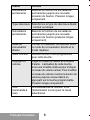
Button Function
Scrambling
Enable/
Disable
Enables or disables scrambling feature
for the selected channel. Applicable for
Long Press only.
Squelch
Level
Selects desired squelch level: Normal
or Tight.
Sticky
Monitor
Toggles the permanent monitor
function until the button is pressed
again. Applicable for Long Press Only.
Talkaround/
Repeater
Mode
Enables toggle between repeater and
talkaround mode operations.
Unassigned No function is programmed to this
button.
Volume Set Controls the audio level. The button
emits a continuous tone to indicate the
current volume level. To change
volume level, turn the volume knob to
the desired level while pressing the
programmable button. Applicable for
Long Press Only.
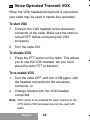
VOX Enables or disables VOX feature for
the selected channel.
CP185_QRC_Bilingual_A7.book Page 8 Monday, November 9, 2015 12:17 PM

9
English
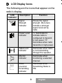
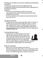
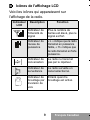
LCD Display Icons
The following are the icons that appear on the
radio’s display
.
LCD
Indicator
Description Function
Signal
Strength
Indicator
Shows the signal
strength. More bars
indicate a stronger
signal received by
radio.
Power Level
Indicator
“L” illuminates to
indicate radio is
configured to transmit
in low power; “H”
illuminates when radio
transmits in high power.
Talkaround
Indicator
Illuminates when radio
is not transmitting
through the repeater.
Monitor
Indicator
Illuminates when
monitoring a selected
channel.
Voice
Inversion
Scrambling
Indicator
Illuminates when
Scrambling Mode is
ON.
CP185_QRC_Bilingual_A7.book Page 9 Monday, November 9, 2015 12:17 PM

10
English
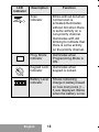
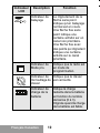
LCD
Indicator
Description Function
Scan
Indicator
Blinks without dot when
normal scan is
activated.Illuminates
without dot when there
is some activity on a
non-priority channel.
Illuminates with dot
blinking to indicate that
there is some activity
on the priority channel.
Prog. Mode
Indicator
Illuminates when
Programming Mode is
ON.
Keypad Lock
Indicator
Illuminates when
keypad is locked.
Battery Level
Indicator
Shows remaining
charge in battery based
on how many bars (1 –
3) are displayed. Blinks
when the battery is low.
CP185_QRC_Bilingual_A7.book Page 10 Monday, November 9, 2015 12:17 PM

11
English
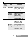
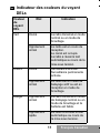
LED Color Indicators
LED
Color
State Indication
Green
Illuminated Radio is transmitting in
normal mode. Radio is
transmitting in
Scrambling Mode.
Normal
Blinking
Radio is receiving in
normal mode.
Channel is busy.
Radio passed self-test
during powering up.
Amber Illuminated Monitor activated.
Permanent Sticky
Monitor activated.
Normal
Blinking
Radio is in active Scan
Mode. Radio is
receiving in
Scrambling Mode.
CP185_QRC_Bilingual_A7.book Page 11 Monday, November 9, 2015 12:17 PM

12
English
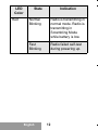
LED
Color
State Indication
Red Normal
Blinking
Radio is transmitting in
normal mode. Radio is
transmitting in
Scrambling Mode
while battery is low.
Fast
Blinking
Radio failed self-test
during powering up.
CP185_QRC_Bilingual_A7.book Page 12 Monday, November 9, 2015 12:17 PM

13
English
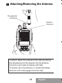
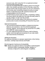
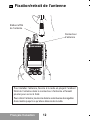
Attaching/Removing the Antenna
CP185
Antenna
Connector
Threaded End
of Antenna
To attach, fasten the antenna to the radio by placing
the threaded end of the antenna into the Antenna
Connector and rotate clockwise until tight.
To remove, turn the antenna in a counterclockwise
direction until it disengages from the radio.
CP185_QRC_Bilingual_A7.book Page 13 Monday, November 9, 2015 12:17 PM

14
English
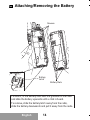
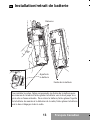
Attaching/Removing the Battery
Battery Slots
Grooves
Battery
Latch
To attach, fit the battery slots with the grooves on the radio
and slide the battery upwards until a click is heard.
To remove, slide the battery latch away from the radio,
slide the battery downwards and pull it away from the radio.
CP185_QRC_Bilingual_A7.book Page 14 Monday, November 9, 2015 12:17 PM

15
English
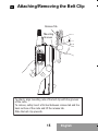
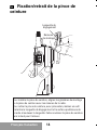
Attaching/Removing the Belt Clip
To attach, align mounting rails of the belt clip with the grooves
of the radio.
To remove, safely insert a flat tool between release tab and the
back surface of the radio and lift the release tab.
Slide the belt clip upwards.
Release Tab
Mounting
Grooves
CP185_QRC_Bilingual_A7.book Page 15 Monday, November 9, 2015 12:17 PM

16
English
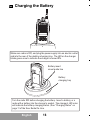
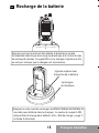
Charging the Battery
Make sure radio is OFF , and plug the power supply into an electric outlet
and into the rear of the desktop charging tray. The LED on the charger
blinks green once to indicate the charger is turned ON.
CP185
Turn the radio OFF before charging the battery. Insert a battery, or a
radio with a battery into the charger’s pocket. The charger’s LED color
will indicate the battery charging status. (See “Charging Status” on
page 11 of the User Guide On-Line.
Battery insert
visual guide line
Battery
charging tray
CP185_QRC_Bilingual_A7.book Page 16 Monday, November 9, 2015 12:17 PM

17
English
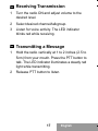
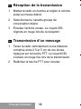
Receiving Transmission
1 Turn the radio ON and adjust volume to the
desired level.
2 Select desired channel/talkgroup.
3 Listen for voice activity. The LED indicator
blinks red while receiving.
Transmitting a Message
1 Hold the radio vertically at 1 to 2 inches (2.5 to
5cm) from your mouth. Press the PTT button to
talk. The LED indicator illuminates a steady red
light while transmitting.
2 Release PTT button to listen.
CP185_QRC_Bilingual_A7.book Page 17 Monday, November 9, 2015 12:17 PM

18
English
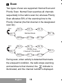
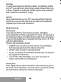
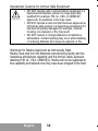
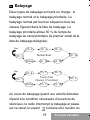
Scan
Two types of scan are supported: Normal Scan and
Priority Scan. Normal Scan searches all channels
sequentially in the radio’s scan list, whereas Priority
Scan allocates 50% of the scanning time to the
Priority Channel (the first channel in the designated
scan list).
During scan, when activity is detected that meets
the unsquelch condition, the radio stops scanning
and switches to that channel; the
indicator is
illuminated, and the channel number is displayed.
Ch. 2
Ch. 3
Ch. 4
Ch. 1
Ch. 15
Ch. 14
Ch. 16
Home
Normal Scan
Start
Ch. 2
Ch. 1
Ch. 3
Ch. 1
Ch. 16
Ch. 1
Ch. 1
Home
Start
Priority Scan
Channel 1 Prioritized
CP185_QRC_Bilingual_A7.book Page 18 Monday, November 9, 2015 12:17 PM
La page est en cours de chargement...
La page est en cours de chargement...
La page est en cours de chargement...
La page est en cours de chargement...
La page est en cours de chargement...
La page est en cours de chargement...
La page est en cours de chargement...
La page est en cours de chargement...
La page est en cours de chargement...
La page est en cours de chargement...
La page est en cours de chargement...
La page est en cours de chargement...
La page est en cours de chargement...
La page est en cours de chargement...
La page est en cours de chargement...
La page est en cours de chargement...
La page est en cours de chargement...
La page est en cours de chargement...
La page est en cours de chargement...
La page est en cours de chargement...
La page est en cours de chargement...
La page est en cours de chargement...
La page est en cours de chargement...
La page est en cours de chargement...
La page est en cours de chargement...
La page est en cours de chargement...
La page est en cours de chargement...
La page est en cours de chargement...
La page est en cours de chargement...
La page est en cours de chargement...
La page est en cours de chargement...
La page est en cours de chargement...
La page est en cours de chargement...
La page est en cours de chargement...
La page est en cours de chargement...
La page est en cours de chargement...
La page est en cours de chargement...
La page est en cours de chargement...
La page est en cours de chargement...
La page est en cours de chargement...
La page est en cours de chargement...
La page est en cours de chargement...
La page est en cours de chargement...
La page est en cours de chargement...
La page est en cours de chargement...
La page est en cours de chargement...
La page est en cours de chargement...
La page est en cours de chargement...
La page est en cours de chargement...
La page est en cours de chargement...
La page est en cours de chargement...
La page est en cours de chargement...
La page est en cours de chargement...
La page est en cours de chargement...
La page est en cours de chargement...
La page est en cours de chargement...
La page est en cours de chargement...
La page est en cours de chargement...
La page est en cours de chargement...
La page est en cours de chargement...
La page est en cours de chargement...
La page est en cours de chargement...
La page est en cours de chargement...
La page est en cours de chargement...
La page est en cours de chargement...
La page est en cours de chargement...
-
 1
1
-
 2
2
-
 3
3
-
 4
4
-
 5
5
-
 6
6
-
 7
7
-
 8
8
-
 9
9
-
 10
10
-
 11
11
-
 12
12
-
 13
13
-
 14
14
-
 15
15
-
 16
16
-
 17
17
-
 18
18
-
 19
19
-
 20
20
-
 21
21
-
 22
22
-
 23
23
-
 24
24
-
 25
25
-
 26
26
-
 27
27
-
 28
28
-
 29
29
-
 30
30
-
 31
31
-
 32
32
-
 33
33
-
 34
34
-
 35
35
-
 36
36
-
 37
37
-
 38
38
-
 39
39
-
 40
40
-
 41
41
-
 42
42
-
 43
43
-
 44
44
-
 45
45
-
 46
46
-
 47
47
-
 48
48
-
 49
49
-
 50
50
-
 51
51
-
 52
52
-
 53
53
-
 54
54
-
 55
55
-
 56
56
-
 57
57
-
 58
58
-
 59
59
-
 60
60
-
 61
61
-
 62
62
-
 63
63
-
 64
64
-
 65
65
-
 66
66
-
 67
67
-
 68
68
-
 69
69
-
 70
70
-
 71
71
-
 72
72
-
 73
73
-
 74
74
-
 75
75
-
 76
76
-
 77
77
-
 78
78
-
 79
79
-
 80
80
-
 81
81
-
 82
82
-
 83
83
-
 84
84
-
 85
85
-
 86
86


Motorola CP185 Series Quick Reference Manual
- Catégorie
- Radios bidirectionnelles
- Taper
- Quick Reference Manual
dans d''autres langues
- English: Motorola CP185 Series
Documents connexes
-
Motorola CT150 Manuel utilisateur
-
-
-
-
-
-
-
-
-