Shindaiwa 89301 Manuel utilisateur
- Catégorie
- Coupe-herbe
- Taper
- Manuel utilisateur
Ce manuel convient également à

T3410
Part Number 89301 Rev. 06/2009
T3410/EVC TRIMMER
T3410X/EVC TRIMMER
SHINDAIWA OWNER’S/OPERATOR’S MANUAL
T3410X
English................1
Español.........SP_1
Françias........FR_1
WARNING!
Minimize the risk of injury to yourself and
others! Read this manual and familiarize yourself
with the contents. Always wear eye and hearing pro-
tection when operating this unit.

2
The Shindaiwa C4 series of hand-held
power equipment is designed and built
to deliver superior performance and reli-
ability without compromise to quality,
comfort, safety or durability. Shindaiwa
engines represent the leading edge of high-
performance engine technology, delivering
exceptionally high power with remarkably
low displacement and weight. As an owner/
operator, you’ll soon discover for yourself
why Shindaiwa is simply in a class by itself!
Warning and Operational Labels
Introduction
Throughout this manual are special “atten-
tion statements”.
Attention Statements
WARNING!
A statement preceded by the
triangular attention symbol and the
word “WARNING” contains information
that should be acted upon to prevent
serious bodily injury.
CAUTION!
A statement preceded by the word
“CAUTION” contains information
that should be acted upon to prevent
mechanical damage.
IMPORTANT!
A statement preceded by the word
“IMPORTANT” is one that possesses spe-
cial significance.
NOTE:
A statement preceded by the word “NOTE”
contains information that is handy to know
and may make your job easier.
DANGER!
A statement preceded by the
triangular attention symbol and the
word “DANGER” contains information
that should be acted upon to prevent
serious injury or death.
Safety...........................................................3
Product Description...................................5
Specifications..............................................5
Assembly.....................................................6
Mixing fuel................................................10
Filling the fuel tank..................................10
Starting the Engine .................................11
Stopping the Engine ................................12
Adjusting Engine Idle..............................12
Checking Unit Condition.........................12
Operation ..................................................13
Maintenance.............................................15
Long Term Storage..................................19
Troubleshooting Guide ...........................20
Emission System Warranty Statement ..23
Shindaiwa Inc. reserves the right to make
changes to products without prior notice,
and without obligation to make alterations
to units previously manufactured.
IMPORTANT!
The information contained in these instruc-
tions describes units available at the time
of publication.
Contents
PAGE PAGEPAGE
IMPORTANT!
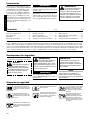
The operational procedures described in this manual are intended to help you get the most from this unit as well as to protect you and oth-
ers from harm. These procedures are guidelines for safe operation under most conditions, and are not intended to replace any safety rules
and/or laws that may be in force in your area. If you have questions regarding your C4 series hand-held power equipment, or if you do not
understand something in this manual, contact Shindaiwa Inc. at the address printed on the back of this Manual.
WARNING!
The engine exhaust from this
product contains chemicals known to
the State of California to cause can-
cer, birth defects or other reproduc-
tive harm.
Read and follow this operator's
manual. Failure to do so could
result in serious injury..
Wear eye and hearing protection
at all times during operation of this
unit. Wear head protection where
there is a risk of falling objects.
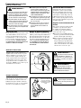
Beware of thrown or richocheted
objects
Make sure no one is within 15 M /
50 feet of an operating machine.
50 FEET
(15m
)
DO NOT operate this unit with a
blade unless the unit is equipped
with a Shindawia-approved
handlebar or barrier.
Always wear a harness when op-
erating this unit with a blade. A har-
ness is also recommended when
using trimmer line.
If unit is used as a brushcutter,
beware of blade thrust. A jammed
blade can cause the unit to jerk
suddenly and may cause the op-
erator to lose control of the unit.

T3410
T3410X
READ THE
OPERATOR’ S M ANUAL
WEAR H EARI NG AN D AN SI Z8 7. 1
AP PRO VED EYE P RO TECTI ON
KEEP BYSTAN DER S AW AY
AT LEAST 5 0 FEET ( 1 5 m )
BEWARE OF THROW N OR
RI COCHETED OBJ ECTS
DO N OT O PERATE THIS
MACHINEWITH A BLADE
5 0 FEET
(15m)
19422-00028Sh in d aiwa Inc.
3
ALWAYS inspect unit before each use.
Replace any damaged parts.
NEVER run the engine when transport-
ing the unit.
NEVER run the engine indoors! Make
sure there is always good ventilation.
Fumes from engine exhaust can cause
serious injury or death.
ALWAYS stop the unit immediately if
it suddenly begins to vibrate or shake.
Inspect for broken, missing or improperly
installed parts or attachments.
NEVER extend trimming line beyond the
OHQJWKVSHFL¿HGIRU\RXUXQLW
ALWAYS keep the unit as clean as prac-
tical. Keep it free of loose vegetation,
mud, etc.
ALWAYSKROGWKHXQLW¿UPO\ZLWKERWK
hands when cutting or trimming, and
maintain control at all times.
ALWAYS use the proper cutting tool for
the job.
ALWAYS keep the handles clean.
ALWAYS disconnect the spark plug wire
before performing any maintenance
work.
ALWAYS, if a saw blade should bind fast
in a cut, shut off the engine immediately.
Push the branch or tree to ease the bind
and free the blade.
Work Safely
Trimmers and brushcutters operate at
very high speeds and can do serious dam-
age or injury if they are misused or abused.
Never allow a person without training or
instruction to operate this unit!
Stay Alert
You must be physically and mentally fit to
operate this unit safely.
Safety
WARNING!
Never make unauthorized
attachment installations.
WARNING!
Never operate
power equipment of any kind
if you are tired or if you are under the
LQÀXHQFHRIDOFRKROGUXJVPHGLFD-
tion or any other substance that could
affect your ability or judgement.
WARNING!
Use Good Judgment
Safety Labels
IMPORTANT!
Safety and Operation Information Labels: Make sure all
information labels are undamaged and readable. Imme-
diately replace damaged or missing information labels.
New labels are available from your local authorized
Shindaiwa dealer.

4
Be Aware of the Working Environment
Avoid long-term
operation in very hot
or very cold weather.
Make sure
bystanders
or observers
outside the
15 meter (50
feet) “danger
zone” wear eye
protection.
Be extremely careful
of slippery terrain,
especially during rainy
weather.
If contact is made with a hard object,
stop the engine and inspect the cutting
attachment for damage.
Be constantly alert for
objects and debris that
could be thrown either
from the rotating cutting
attachment or bounced
from a hard surface.
Reduce the risk of bystanders being
VWUXFNE\À\LQJGHEULV0DNHVXUHQR
one is within 15 meters (50 feet)—
that’s about 16 paces of an operating
attachment. Stop immediately if a child,
pet, or person comes within a 15 meter
(50 feet)radius. Outside this radius,
there is still a risk of injury from thrown
objects.
Beware of a coasting
blade when brushcutting or
edging. A coasting blade
can injure while it continues
to spin after the throttle
trigger is released or after
the engine is stopped.
ALWAYS clear your work area of trash
or hidden debris that could be thrown
back at you or toward a bystander.
When operating in rocky terrain or
near electric wires or fences, use
extreme caution to avoid contacting
such items with the cutting attachment.
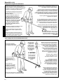
The Properly Equipped Operator
Always wear a harness when operating the unit .
It adds comfort and helps ensure safety by limiting
movement fore and aft. When the harness is
adjusted properly, the unit should balance with the
cutting attachment parallel to the ground.
Always operate with both hands
¿UPO\JULSSLQJWKHXQLW
:HDUFORVH¿WWLQJFORWKLQJWR
protect legs and arms. Gloves
offer added protection and are
strongly recommended. Do not
wear clothing or jewelry that
could get caught in machinery
or underbrush. Secure long hair
so that it is above shoulder level.
NEVER wear shorts!
Wear hearing protection devices and a
broad-brimmed hat or helmet. A helmet
is required when using a blade-equipped
brushcutter to clear small trees.
Always wear eye protection such as
goggles or safety glasses to shield
against thrown objects.
When operating with a blade, make sure
the handle is positioned to provide you with
maximum protection from contacting the
blade. Always make sure the handlebar
is installed in accordance with the
manufacturers instructions.
Keep away from the rotating
trimmer line or blade at all
times, and never lift a moving
attachment above waist-high.
Wear appropriate footwear (non-skid
boots or shoes): do not wear open-
toed shoes or sandals. Never work
barefooted!
Keep a proper footing and do not
overreach. Maintain your balance at all
times during operation.
Always make sure the
appropriate cutting attachment
shield is correctly installed and
in good condition. Do not
operate the unit if the
cutting attachment shield
is missing, loose, or
broken.
Long-term exposure to vibration
can damage your hands.
Prolonged exposure to excessive noise
is fatiguing and could lead to impaired
hearing.
Do not operate the unit
if the cutting attachment
shield is missing, loose,
or broken.
Safety (continued)
15 METERS
(50 FEET)
Always make sure
the appropriate
cutting attachment
shield is correctly
installed.

5
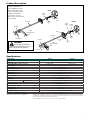
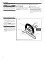
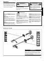
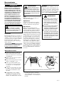
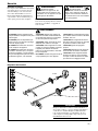
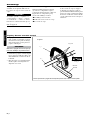
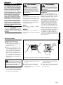
Product Description
Using the illustration as a
guide, familiarize yourself
with your machine and its
various components. Under-
standing your machine
helps ensure top perfor-
mance, long service life and
safer operation.
WARNING!
Do not make unauthorized
PRGL¿FDWLRQVRUDOWHUDWLRQVWRDQ\RI
these units or their components.
6SHFLÀFDWLRQV
Outer Tube
Trimmer Head
Grip
Cutting
Attachment Shield
Gearcase
Handle
Throttle
Trigger
Throttle
Interlock
Ignition
Switch
Fuel
Tank
Barrier
Bar
Hanger
T3410
Outer Tube
Trimmer Head
Cutting
Attachment Shield
Gearcase
Throttle
Trigger
Ignition
Switch
Fuel
Tank
T3410X
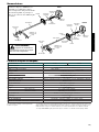
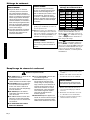
Engine Name T3410 T3410X
Engine Model SF3410E
Engine Type 4-cycle, vertical cylinder, air cooled
Dry Weight (Without guard and strap) 5.9 kg/13.0 lb. 6.0 kg/13.2 lb
Bore x Stroke 1.5 x 1.2 in./ 38 x 30 mm
Displacement 34 cc/2.1 cu. in.
Maximum Power Output 1.4 HP (1.0 kW) @ 8000 (min
-1
)
Engine Idle Speed
3,000 (±300) min
-1
Fuel/Oil Ratio 50:1 with ISO-L-EGD or JASO FD class 2-cycle mixing oil
Fuel Tank Capacity
700 ml/23.7 oz.
Carburetor Type Walbro, WYL, diaphragm-type
Ignition One-piece electronic, program-controlled
Spark Plug** NGK CMR5H
Spark Plug Gap 0.6 - 0.7 mm (0.024 - 0.028 inch)
Torque 100-150 kg cm / 9.8 - 14.7 N∙m
Engine Idle Speed
3,000 (±300) min
-1
Air Cleaner Type Foam pre-filter; sealed felt main filter
Starting Method Recoil
Stopping Method Slide switch
Transmission Type Automatic, centrifugal clutch w/bevel gear
EPA Emission Compliance Period* Category A
Specifications are subject to change without notice.
* The EPA emission compliance period referred to on the emission compliance label located on the engine, indicates the number
of operating hours for which the engine has been shown to meet Federal emission requirements. Category C = 50 hours (Moder-
ate), B = 125 hours (Intermediate) and A = 300 hours (Extended)
** The NGK CMR5H also meets the requirements for electro magnetic compliance (EMC).

X uni
t
O
uter Tub
e
H
an
dl
e
B
a
rri
e
r B
a
r
4
S
ocket-head
capscre
w
s
H
an
dl
e
p
os
i
t
i
on
l
a
b
e
l
Th
e
h
an
dl
e is attac
h
e
d
at t
h
e factory an
d
p
ositione
d
vertica
ll
y
.
L
oosen soc
k
et
h
ea
d
e
d
capscrew
(
s
)
at
1.
the
base
o
f
ha
n
dle
a
n
d
r
otate
the
ha
n
-
dle 90 degrees
.
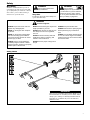
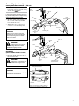
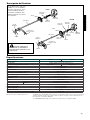
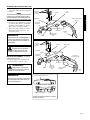
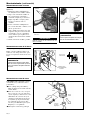
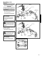
Handle and barrier bar X uni
t
N
O
TE
:
K
eep handle forward of handle posi
-
t
ioning label!
P
os
i
t
i
o
n
t
h
e
h
a
n
d
l
e
f
o
rw
a
r
d
o
f
t
h
e
2.
Han
dl
e Positionin
g
La
b
e
l
at t
h
e
b
es
t
position for operator comfort
(
usua
lly
about 254 mm (10 in.) ahead of throttle
h
ousin
g)
.
Ti
gh
ten t
h
e soc
k
et
h
ea
d
e
d
ca
p
scre
w
3.
s
ecurel
y
.
R
otate and
p
osition handle in best location
f
or o
p
erator com
f
ort
6
A
ssem
bly
T
his unit comes full
y
assembled with the
e
xception of the cutting attachment shield
a
n
d
cuttin
g
attac
h
ment
.
Prior to Assembl
y
B
efore assem
bl
ing, ma
k
e sure you
h
ave a
ll
t
h
e com
p
onents re
q
uire
d
for a com
pl
ete
u
nit and inspect unit and components for
a
ny
d
amage.
Engine an
d
s
h
aft assem
bly
Ŷ
Cuttin
g
attachment shiel
d
Ŷ
Cutting attachmen
t
Ŷ
K
it containing cutting attachment
Ŷ
s
h
ie
ld
, mountin
g
b
rac
k
et an
d
h
ar
d
ware,
this owner’s/o
p
erator’s manual and tool
kit for routine maintenance. Tool kits
vary
b
y mo
d
e
l
an
d
may inc
l
u
d
e a spar
k
p
lu
g
/screwdriver combination wrench,
a
nd a scraper.
IMPORTANT!
Th
e terms “
l
eft”
,
“
l
eft-
h
an
d
”
,
an
d
“LH”;
“right”, “right-hand”, and “RH”; “front” and
“rear” refer to
d
irections as viewe
d
b
y t
h
e
o
p
erator
d
urin
g
norma
l
o
p
eration
.
T
his unit comes full
y
assembled with the
e
xce
p
tion of t
h
e cuttin
g
attac
h
ment s
h
ie
ld
and cuttin
g
attachment.

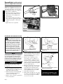
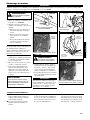
WARNING!
NEVER use this machine with-
out sub-shield when using a trimmer
head.
T unit
TX unit
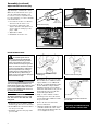
CAUTION!
Make sure the sub-shield is completely
hooked at the hook receiver.
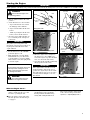
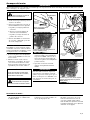
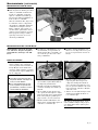
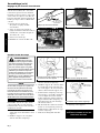
Sub-Shield
(when trimmer head is in use)
Attach the shield extension to the cut-1.
ting attachment shield.
Sub-shield
Hook
Hook Receiver
Cutting Attachment Shield
Attach the sub-shield to the cutting attachment
shield for TX units when using a trimmer head
Outer Tube
Socket-Head
Cap Screws
Clamp Screw
Retaining
Nut
Mounting Plate
Shim
Shim
Bracket
Cutting Attachment
Shield w/subshield
Line Cutter
Outer Tube
Socket-
Head Cap
Screws
Clamp Screw
Retaining
Nut
Mounting Plate
Shim
Shim
Bracket
Line Cutter
Cutting
Attachment Shield
Cutting Attachment Shield - T, TX unit
7
CAUTION!
Make sure the clamp screw and
retaining nut are securely tightened
before tightening the four socket-
head cap screws.
Assembly (continued)
Insert the cutting attachment shield 1.
between the outer tube and the cutting
attachment mounting plate.
WARNING!
NEVER operate the unit with-
out the cutting attachment shield
installed and tightly secured!
NOTE:
It may be necessary to loosen the retain-
ing nut and clamp screw to adjust cutting
attachment shield mounting plate.
Fit the two shims and the bracket over 2.
the outer tube and loosely install the
four socket-head screws.
Tighten the four socket-head cap 3.
screws to secure the cutting attach-
ment shield.

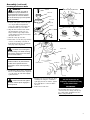
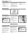
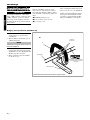
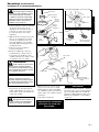
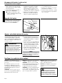
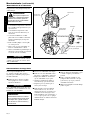
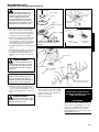
NOTE:
This unit is shipped with Holder A, the
blade retainer (safety clip), Holder B, shaft
bolt, and bolt guard installed. The shaft
bolt is a LEFT-HAND thread. Remove it
by turning CLOCKWISE!
Install Holder
A
Install Holder
B
Safety Clip
Hex Wrench
Hand-tighten
trimmer head
Throttle lever free play
4-6 mm
(3/16”-1/4”)
Throttle Free Play
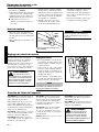
Position the gearcase with the output
shaft facing up
Securely tighten the trimmer head into the
gearcase shaft
Install and center the safety clip
Position the gearcase with the output 1.
shaft facing up and remove both holders.
Position Holder A as shown and slide it 2.
onto the gearcase shaft.
Install and center the safety clip on the 3.
gearcase shaft.
Install Holder B on the gearcase shaft. 4.
The machined boss on Holder A must
engage with the recess on Holder B.
Rotate the gearshaft and holders until 5.
the hole in Holder A aligns with the
matching hole in the gearcase flange,
and then lock the holder to the gearcase
by inserting the long end of the hex
wrench through both holes.
Using a counter-clockwise rotation 6.
and hand pressure alone, thread and
securely tighten the trimmer head into
the gearcase shaft.
Remove the hex wrench from the 7.
gearcase and holders.
Adjust the trimmer line length to reach 8.
no further than the line cutter on the
cutting attachment shield. Trim to the
correct length if necessary.
IMPORTANT
To install a trimmer head onto a TX
unit, first remove the shaft bolt and
bolt guard.
The unit should now be
completely assembled and ready
for use with a trimmer head.
Install trimmer head
WARNING!
A standard grass trimmer
with a loop handle should NEVER
be operated with blade-type attach-
ments. For blade use, the trimmer
PXVWEH¿WWHGZLWKDELF\FOHW\SHKDQ-
dlebar or a barrier bar that is located
in front of the operator to reduce the
risk of the operator from coming in
contact with the cutting attachment
(per ANSI B175.3). When using a
blade, the unit must also be equipped
with a harness or strap.
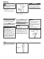
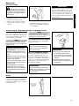
Remove air cleaner cover
Lock Nut
Cable
Adjuster
Adjust as required for 4-6 mm free play
8
Assembly (continued)
Adjust throttle lever free play
The throttle lever free play should be
approximately 4 - 6 mm (3/16” - 1/4”).
Make sure that the throttle lever oper-
ates smoothly without binding. If it
becomes necessary to adjust the lever
free play, follow the procedures and illus-
trations that follow.
Loosen the air cleaner cover knob(s) 1.
and remove the air cleaner cover.
Loosen the lock nut on the cable 2.
adjuster. Turn the cable adjuster in or
out as required to obtain proper free
play 4 - 6 mm.
Tighten the locknut.3.
Reinstall the air cleaner cover.4.

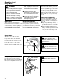
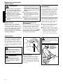
Turn the unit upside down so the gear 1.
case output shaft is facing UP and
remove the shaft bolt, bolt guard and
holder B from the gear case shaft.
Align the hole in blade holder A with 2.
the matching hole in the gear case
flange and then temporarily lock the
output shaft by inserting a hex wrench
through both holes.
Slide the safety clip off-center3.
Fit the blade over the safety clip and then 4.
center it over the flange on holder A.
Lock the blade in place by centering the
safety clip on the output shaft.
CAUTION!
Install the blade so its printed surface
is visible to the operator when the
brushcutter is in the normal operating
position.
WARNING!
7KHEODGHPXVW¿WÀDWDJDLQVW
WKHKROGHUÀDQJH7KHEODGHPRXQWLQJ
hole must be centered over the raised
boss on blade Holder A.
WARNING!
+ROGHU%PXVW¿WÀXVKDJDLQVW
the blade and the splines engaged to
the output shaft.
Install blade holder B on the output shaft. 5.
The recess in the holder must completely
cover the safety clip, and must fit tightly
against the blade.
Install the bolt guard and then the blade 6.
retaining bolt. Using the combination
spark plug wrench/screwdriver, tighten
the bolt firmly in a counter-clockwise
direction.
Remove the hex wrench.7.
WARNING!
Do not attach any blade to
a unit without proper installation of
all required parts. Failure to use the
proper parts can cause the blade to
À\RIIDQGVHULRXVO\LQMXUHWKHRSHUDWRU
and/or bystanders.
The unit should now be
completely assembled and ready
for use with a blade.
IMPORTANT!
Discard blades that are bent, warped,
cracked, broken or damaged in any way.
Use a sharp blade. A dull blade is more
likely to snag and thrust.
Slide the safety clip off-center
Slip the Saw Blade
In Place
Slide the Safety Clip
Back
Shaft Bolt
Bolt Guard
Holder B
Gear shaft
Holder A
Blade
Hex Wrench
Blade Holder B
Tighten the assembly
(blade not shown for
clarity)
Safety Clip
Safety Clip
Output Shaft
Output Shaft
Hex
Wrench
Installing Brushcutter Blade
9
Assembly (continued)

10
CAUTION
Never use any type of gasoline contain-
ing more than 10% alcohol by volume!
Some types of gasoline contain alcohol
as an oxygenate. Oxygenated gaso-
line may cause increased operating
temperatures. Under certain condi-
tions, alcohol-based gasoline may also
reduce the lubricating qualities of some
2-cycle mixing oils.
Generic oils and some outboard
oils should never be used in your
Shindaiwa engine.
Mixing fuel
Filling the fuel tank
CAUTION
This engine is designed to operate on
a 50:1 mixture consisting of unleaded
gasoline and ISO-L-EGD or JASO FD
class 2-cycle mixing oil only. Use of
non-approved mixing oils can lead to
excessive carbon deposits.
Use only fresh, clean unleaded gasoline Ŷ
with a pump octane of 87 or higher.
Mix all fuel with a 2-cycle air-cooled
Ŷ
mixing oil that meets or exceeds ISO-L-
EGD and/or JASO FD classified oils at
50:1 gasoline/oil ratio.
Examples of 50:1 mixing quantities
WARNING!
Minimize the Risk of Fire
IMPORTANT!
Mix only enough fuel for your immediate
needs! If fuel must be stored longer than 30
days and
oil with fuel stabilizer is not
used, it should first be treated with a fuel
stabilizer such as STA-BIL™.
Oil is a registered JASO FD classi-
fied oil and also meets or exceeds ISO-L-EGD
performance requirements. Shindaiwa One is
recommended for use in all Shindaiwa low emis-
sions engines. Shindaiwa One also includes a
fuel stabilizer.
NEVERŶ VPRNHRUOLJKW¿UHVQHDUWKH
engine.
ALWAYS
Ŷ stop the engine and allow
it to cool before refueling.
ALWAYS
Ŷ Wipe all spilled fuel and
move at least 3 meters (10 feet)
from the fueling point and source
before starting.
NEVER
Ŷ SODFHÀDPPDEOHPDWHULDO
FORVHWRWKHHQJLQHPXIÀHU
NEVER
Ŷ operate the engine with-
RXWWKHPXIÀHUDQGVSDUNDUUHVWHU
screen in place and in good work-
ing condition.
FUEL IS HIGHLY FLAMMABLE.
Ŷ
ALWAYS Ŷ store gasoline in a con-
WDLQHUDSSURYHGIRUÀDPPDEOH
liquids.
ALWAYS
Ŷ
inspect the unit for fuel
leaks before each use. During each
UH¿OOFKHFNWKDWQRIXHOOHDNVIURP
around the fuel cap and/or fuel tank.
If fuel leaks are evident, stop using
the unit immediately. Fuel leaks must
be repaired before using the unit.
ALWAYSŶ move the unit at least 3
meters (10 feet) away from a fuel
VWRUDJHDUHDRURWKHUUHDGLO\ÀDP-
mable materials before starting
the engine.
Place the unit on a flat, level surface.1.
Clear any dirt or other debris from 2.
around the fuel filler cap.
Remove the fuel cap, and fill the tank 3.
with clean, fresh fuel.
Reinstall the fuel filler cap and tighten 4.
firmly.
Wipe away any spilled fuel before start-5.
ing engine.
CAUTION!
Slowly remove the fuel cap only after
stopping the engine
CAUTION!
Mix and pour fuel outdoors where there
DUHQRVSDUNVDQGÀDPHV
U.S. METRIC
Gasoline
2-cycle
mixing oil
Gasoline
2-cycle
mixing oil
US Gallons Fl.oz. Liter cc.
1 2.6 4 80
2 5.2 8 160
5 13 20 400
10 25.6 30 600
20 51.2 50 1000
50 128 100 2000

Slide ignition to ON
ON
Throttle Lock
Button
Make sure the
attachment is clear
of obstructions!
...and pull recoil
starter handle
upward
Hold
the unit
¿UPO\
Open
After engine starts, move choke to OPEN
position
Primer Bulb
Return Tube
Press primer
bulb...
Close
choke
Set the choke lever to the CLOSED position
11
Starting the Engine
IMPORTANT!
Engine ignition is controlled by a two position switch mounted on the throttle housing labeled, “I” for ON or START and “O” for OFF or STOP.
Slide the ignition switch to the “ON” 1.
position.
Set the throttle lever to the “fast idle”:2.
Squeeze the throttle lever toward a.
the handgrip on the shaft tube.
Depress and hold the throttle lock b.
button.
While depressing the throttle lock c.
button, release the throttle lever.
Press the primer bulb until fuel can 3.
be seen flowing in the transparent
return tube.
WARNING!
Never start the engine from
the operating position.
Set the choke lever to the CLOSED 4.
position if engine is cold.
While holding the outer tube firmly 5.
with left hand. Use your other hand
to slowly pull the recoil starter handle
until resistance is felt, then pull quickly
to start the engine.
IMPORTANT!
The primer system only pushes fuel
through the carburetor. Repeatedly press-
ing the primer bulb will not flood the
engine with fuel.
CAUTION!
Do not pull the recoil starter to the end
of the rope travel. Pulling the recoil
starter to the end of the rope travel
can damage the starter.
WARNING!
The cutting attachment may
move when the engine is started!
IMPORTANT!
If the engine fails to start after several
attempts with the choke in the closed
position, the engine may be flooded with
fuel. If flooding is suspected, refer to the
”Starting a Flooded Engine” section of
this manual.
When the engine starts, slowly move 6.
the choke lever to the “OPEN” posi-
tion. (If the engine stops after the initial
start, close the choke and restart.)
Operating the throttle will automatically 7.
disengage the fast idle setting.
After the engine starts, allow the
Ŷ
engine to warm up at idle 2 or 3 min-
utes before operating the unit.
After the engine is warm, pick up the
Ŷ
unit and clip on the shoulder strap, if
so equipped.
When the Engine Starts...
Advancing the throttle makes the cutting Ŷ
attachment move faster; releasing the
throttle permits the attachment to stop
moving. If the cutting attachment con-
tinues to move when the engine returns
to idle, carburetor idle speed should be
adjusted (see “Adjusting Engine Idle”.).

Slide ignition to OFF
OFF
NEVER operate the unit with the cut-
ting attachment shield or other protec-
tive devices removed!
Use only authorized Shindaiwa parts and
accessories with your Shindaiwa trimmer.
Do not make modifications to this unit with-
out written approval from Shindaiwa, Inc.
ALWAYS make sure the cutting attach-
ment is properly installed and firmly
tightened before operation.
NEVER use a cracked or warped
cutting attachment: replace it with a
serviceable one.
Checking Unit Condition
ALWAYS make sure the cutting attach-
ment fits properly into the appropriate
attachment holder. If a properly installed
attachment vibrates, replace the attach-
ment with new one and re-check.
ALWAYS stop the engine immediately
and check for damage if you strike a
foreign object or if the unit becomes
tangled. Do not operate with broken or
damaged equipment.
NEVER allow the engine to run at high
RPM without a load. Doing so could dam-
age the engine.
NEVER operate a unit with worn or dam-
aged fasteners or attachment holders.
WARNING!
A cutting attachment shield or
other protective device is no guarantee
of protection against ricochet. YOU
MUST ALWAYS GUARD AGAINST
FLYING DEBRIS!
12
Idle the engine briefly before stopping
(about 2 minutes), then slide the ignition
switch to the “O” (Engine OFF) position.
Stopping the Engine
Adjusting Engine Idle
Idle Adjusting
Screw
The engine must return to idle speed
whenever the throttle lever is released.
Idle speed is adjustable, and must be set
low enough to permit the engine clutch to
disengage the cutting attachment.
WARNING!
The cutting attachment must
NEVER rotate at engine idle! If the
idle speed cannot be adjusted by
the procedure described here, return
the unit to your Shindaiwa dealer for
inspection.
Idle Speed Adjustment
Place the unit on the ground, then start 1.
the engine, and then allow it to idle 2-3
minutes until warm.
If the attachment rotates when the 2.
engine is at idle, reduce the idle speed
by turning the idle adjustment screw
counter-clockwise.
If a tachometer is available, adjust idle. 3.
Check Specifications page for correct
idle speed
Starting the Engine (continued)
NOTE
Carburetor fuel mixture adjustments are
preset at factory and cannot be serviced
LQWKH¿HOG
Disconnect the spark plug lead and use 1.
the spark plug wrench to remove the
spark plug (turn counter clockwise to
remove).
Slide the ignition switch to the “O” 2.
(STOP) position.
If the spark plug is fouled or
Ŷ
soaked with fuel, clean the plug as
necessary.
Open the choke and fully depress the 3.
throttle lever with your left hand, then
pull the starter handle rapidly with your
right hand to clear excess fuel from the
combustion chamber.
Replace the spark plug and tighten it 4.
firmly with the spark plug wrench. If a
torque wrench is available, torque the
spark plug to the values recommended
in the “Specifications” section.
Repeat the starting procedure for a 5.
warm engine.
If the engine still fails to start, refer to 6.
the troubleshooting section near the
end of this manual.
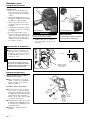
Starting A Flooded Engine

Hook the strap hook to the hanger on 1.
the outer tube.
Wear the shoulder strap so that the 2.
hook stays at your right hand side.
IMPORTANT!
Adjust the shoulder strap or harness so the
shoulder pad rests comfortably on the off-side
shoulder and the cutting path of the cutting
attachment is parallel to the ground. Make sure
all hooks and adjustment devices are secure.
Shoulder Strap
WARNING!
Always wear a shoulder strap
when operating this unit with a blade.
A shoulder strap is also recommened
when using trimmer line.
Adjust the length of the shoulder strap 3.
so that you can hold and operate the
machine comfortably.
CAUTION!
Do not push the rotating line into trees, Ŷ
wire fences or any material that could
tangle or break line ends.
Operation of trimmer without a cutting
Ŷ
attachment shield and using exces-
sive line length can lead to premature
clutch failure.
Operation at low rpm can lead to Ŷ
premature clutch failure.
13
Harness
TX unit
Operation
Your Shindaiwa unit may be equipped with
one of several Shindaiwa trimmer head mod-
els, each with features for specific applica-
tions and/or operational requirements.
Cutting grass with a trimmer head
Trimmer head styles:
Semi-automatic. Trimmer line is indexed
when the operator taps the trimmer head
on the ground during operation.
Manual. The operator indexes line manu-
ally with the grass trimmer stopped.
Fixed.
The operator must stop the unit and
add new lengths of trimmer line manually.
Flail.
This device, designed for clearing
weeds and light brush, features three nylon
blades attached to the head by pivots.
NOTE:
For proper operation, always refer to the
instructions accompanying the trimmer
head being used.
NOTE:
Additional hardware may be required to
mount the Fixed Line or the Flail type
trimmer heads.
CAUTION!
Operation at low rpm can lead to pre-
mature clutch failure.
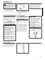
Hold the grass trimmer so the trimmer head
is angled slightly into the area to be cut. To
ensure maximum trimmer-line service life, cut
only with the tip of the trimmer line. Cut grass
by swinging the unit's trimmer head from left
to right. Keep the trimmer head horizontal.
Engine Operating Speeds
Operate at full throttle while cutting grass.
Edging
Tilt the handle about 100° to the left (from
horizontal) and move forward, holding
the trimmer or brushcutter vertically as
shown.
Trimming and Mowing Grass
Tilt the handle about
100° to the left

14
D
O
N
O
T
C
U
T
Before working with a blade-equipped Ŷ
unit, always inspect and clean the
area of objects that could interfere
with or damage the blade.
Never use a blade near sidewalks,
Ŷ
fence posts, buildings or other objects
that could cause injury or damage.
Never use a blade for purposes other Ŷ
than those for which it was designed.
Whenever you strike a hard object with a Ŷ
blade, always stop the brushcutter and
carefully inspect the blade for damage.
NEVER OPERATE THE BRUSHCUT-
TER WITH A DAMAGED BLADE!
A blade-equipped unit must be Ŷ
equipped with a bicycle-type handle-
bar or barrier bar as well as a har-
ness or shoulder strap.
Always make sure the cutting attach-
Ŷ
ment shield is properly installed
before operating this unit.
Using a Blade
Blade Thrust
“Blade thrust” is a sudden sideways or
backward motion of the brushcutter. Such
motion may occur when the blade jams or
catches on an object such as a sapling tree
or tree stump. BE CONSTANTLY ALERT
FOR BLADE THRUST AND GUARD
AGAINST ITS EFFECTS!
Brushcutter harness
A harness provides additional protection
against blade thrust. In addition, a har-
ness gives significant support and comfort
to help ensure safe and efficient opera-
tion. When operating a unit with a blade,
make sure both the handle and harness are
adjusted to the size of the operator using
the unit.
Engine Operating Speeds
Operate the unit at full throttle while cut-
ting. Best fuel efficiency is obtained by
releasing the throttle when swinging back
after a cut.
To prevent possible engine damage, do
Ŷ
not allow the brushcutter to run at high
speeds without a load.
Avoid operating the engine at low speeds.
Ŷ
Doing so can lead to rapid clutch wear. In
addition, slow-speed operation tends to
cause grass and debris to wrap around
the cutting head.
The blade rotates counter-clockwise.
For best performance and to minimize
being stuck by debris, move the blade
from right to left while advancing on your
work. Position the blade so cuts are made
between the blade’s 8 o’clock and 10
o’clock positions (as viewed from above).
DO NOT cut between the 10 o’clock and 5
o’clock positions.
WARNING!
When cutting wood with a
blade, feed the blade slowly—never
strike or “slam” a spinning blade
against the wood.
WARNING!
DO NOT use 2-tooth or non-
Shindaiwa approved 4-tooth cutting
blades with Shindaiwa trimmers and
brushcutters.
Vertical Cuts
Hold the brushcutter with the blade at a
90° angle to the ground so the blade’s bot-
tom edge rotates toward the operator.
Move the blade from top to bottom through
the cut, and cut only with the bottom edge
of the blade.
Using a Blade
Cut on the left
side of the blade.
KEEP YOUR BODY
OUTSIDE THE
PATH OF BLADE
ROTATION
WARNING!
When making vertical cuts,
never allow the blade to exceed waist
height.
Ten
O'clock
OK To Cut
Eight
O'clock
Five
O'clock
Blade
Rotation
Brushcutter Handlebar
A brushcutter handlebar or barrier bar
helps prevent the operator from moving
forward, or the unit moving rearward, thus
preventing inadvertent bodily contact with
the blade. ALWAYS KEEP THE HANDLE-
BAR OR BARRIER BAR SECURELY IN
PLACE ON THE UNIT!
WARNING!
Operation (cont.)

15
Prior to each work day, perform the
following:
Remove all dirt and debris from the
Ŷ
engine, check the cooling fins and
air cleaner for clogging, and clean as
necessary.
Carefully remove any accumulations
Ŷ
of dirt or debris from the muffler and
fuel tank. Check cooling air intake
area at base of crankcase. Remove
all debris. Dirt build-up in these areas
can lead to engine overheating, fire,
or premature wear.
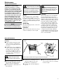
Daily maintenance
Lubricate the blades before use and Ŷ
after refueling. Check the cutters for
damage or incorrect adjustment.
Clean any debris or dirt from the cut-
Ŷ
ting attachment.
5HPRYHDOOGLUWDQGGHEULVIURPWKHHQJLQHDQGFKHFNWKHFRROLQJ¿QV
Cooling
¿QV
Air
intake
Cooling
¿QV
WARNING!
Always wear gloves when
working around the cutter assembly.
Maintenance
WARNING!
Before performing any mainte-
nance, repair, or cleaning work on the
unit, make sure the engine and cutting
attachment are completely stopped.
Disconnect the spark plug wire before
performing service or maintenance.
WARNING!
Non-standard accessories, cut-
ting attachment, or replacement parts
may not operate properly with your unit
and may cause damage and lead to
personal injury.
IMPORTANT!
MAINTENANCE, REPLACEMENT
OR REPAIR OF EMISSION CONTROL
DEVICES AND SYSTEMS MAY BE PER-
FORMED BY ANY REPAIR ESTABLISH-
MENT OR INDIVIDUAL; HOWEVER, WAR-
RANTY REPAIRS MUST BE PERFORMED
BY A DEALER OR SERVICE CENTER
AUTHORIZED BY SHINDAIWA INC. THE
USE OF PARTS THAT ARE NOT EQUIVA-
LENT IN PERFORMANCE AND DURA-
BILITY TO AUTHORIZED PARTS MAY
IMPAIR THE EFFECTIVENESS OF THE
EMISSION CONTROL SYSTEM AND MAY
HAVE A BEARING ON THE OUTCOME
OF A WARRANTY CLAIM.
0XIÁHU
This unit must never be operated with a
faulty or missing spark arrester or muf-
fler. Make sure the muffler is well secured
and in good condition. A worn or damaged
muffler is a fire hazard and may also cause
hearing loss.
Spark Plug
Keep the spark plug and wire connections
tight and clean.
Fasteners
Make sure nuts, bolts, and screws (except
carburetor adjusting screws) are tight.
General maintenancel
NOTE:
Using non-standard replacement parts
could invalidate your Shindaiwa warranty.
Air Filter
The C4 engine that powers your Shindaiwa
model is a hybrid 4-stroke engine. As a
hybrid, the engine is lubricated by oil mixed
with the gasoline and air from the carburetor
that moves through and around the internal
parts of the engine in a similar way that a
2-stroke engine is lubricated. Without the
heavy duty 2-stage air filter equipped on all
C4 engines, dust and dirt could also move
through the engine, decreasing engine life,
increasing valve wear and the need for more
frequent valve adjustments. To keep your
C4 engine strong and reliable, Shindaiwa
recommends that you check and service the
air filter as instructed in the 10-Hour Mainte-
nance section that follows.
Check for loose or missing screws or Ŷ
components. Make sure the cutter
attachment is securely fastened.
Check the entire unit for leaking fuel
Ŷ
or grease.
Make sure nuts, bolts, and screws
Ŷ
(except carburetor idle speed adjusting
screws) are tight.

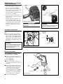
Remove and inspect spark plug
0,6 - 0.7 mm
Clean the spark
plug and check
the gap at the
electrode.
&RPSRQHQWVRIDLU¿OWHU
Filter element
3UH¿OWHU
Loosen
fasteners
5HPRYHWKHFRYHURIWKHDLU¿OWHU
Old
Grease
New
Grease
Gearshaft Collar
Gearcase lubrication
16
50-hour maintenance
CAUTION!
Before removing the spark plug, clean
the area around the plug to prevent
dirt and debris from getting into the
engine’s internal parts.
10/15-Hour maintenance
Maintenance (continued)
10-Hour maintenance
(more frequently in dusty conditions)
Remove the air filter cover by loosen-1.
ing the cover screw(s) and lifting.
Remove and inspect the pre-filter. If 2.
the pre-filter is torn or otherwise dam-
aged, replace it with a new one.
Clean the pre-filter with soap and water. 3.
Let dry before reinstalling.
Inspect the air filter element. If the ele-4.
ment is damaged or distorted, replace it
with a new one.
Tap filter gently on a hard surface to dis-5.
lodge debris from element or use com-
pressed air from the inside to blow debris
out and away from the air filter element.
Install the air filter element, pre-fil-6.
ter and cover in the reverse order of
removal.
IMPORTANT!
Direct the air stream at the inside face of
the filter only!
CAUTION!
Never operate the unit if the air cleaner
assembly is damaged or missing!
Remove and clean or replace the spark
plug.
Clean the spark plug. Adjust electrode
Ŷ
gap according to the values listed in the
”Specifications” section. If the spark plug
must be replaced, use only the type rec-
ommended in ”Specifications” or equiva-
lent resistor type spark plug of the correct
heat range.
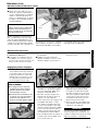
Every 50 hours of operation; more
frequently in dusty conditions:
Remove and clean the cylinder cover
Ŷ
and clean dirt and debris from the cyl-
inder cooling fins.
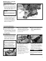
Gearcase lubrication
Remove and clean the cylinder cover
Ŷ
and clean grass and dirt from the cyl-
inder fins.
Remove the cutting attachment, cut-
Ŷ
ting attachment holder and gearshaft
collar. Remove the filler plug from
the side of the gearcase and press
new grease into the gearcase until old
grease is pushed out. Use only lith-
ium-base grease such as Shindaiwa
Gearcase Lubricant or equivalent.
Lubricate mainshaft splines.
Ŷ

)XHO¿OWHUPDLQWHQDQFH
)XHO¿OWHUHOHPHQW
Hooked wire
17
Maintenance (continued)
50-hour maintenance
Remove and replace the fuel filter
element.
Use a hooked wire to extract the fuel filter
Ŷ
from inside the fuel tank. Inspect the fuel
filter element. If it shows signs of contam-
ination, replace with a genuine Shindaiwa
replacement fuel filter element.
CAUTION!
Make sure you do not pierce the fuel line
with the end of the hooked wire. The line
is delicate and can be damaged easily.
139/150-Hour Maintenance
Maintenance after first 139-hours,
then every 150-hours thereafter.
Combustion chamber should be decar-
Ŷ
bonized, and the valve clearance should
be adjusted. It is highly recommended
that this is done by a Shindaiwa-trained
service technician.
Replace the spark plug annually: Use
Ŷ
only the type recommended in the
”Specifications” section or an equivalent
resistor type spark plug of the correct
heat range. Set spark plug electrode
gap to 0.6 -0.7 mm.
The valve clearance should be adjusted
Ŷ
annually or every 135 hours. It is
highly recommended that this is
done by a Shindaiwa-trained service
technician.
Before reinstalling the new filter element,
inspect the condition of all the fuel system
components (fuel pick-up line, fuel return
line, tank vent line, tank vent, fuel cap
and fuel tank). If damage, splitting or
deterioration is noted, the unit should
be removed from service until it can be
inspected or repaired by a Shindaiwa-
trained service technician.
IMPORTANT!
If a new gasket is not available and/or the
old gasket is not damaged, the old gasket
may be reused. Never use cracked or dam-
aged gaskets!
Turn engine over several times, and 6.
returnthe to TDC-compression.
Recheck with proper feeler gauge to
make sure clearance adjustment did
not change as a result of tightening the
locknut. Readjust as necessary.
Replace rocker arm cover gasket to 7.
assure proper sealing and install cover.
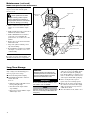
Remove cylinder cover, rocker arm cover, 1.
and spark plug.
Rotate the crankshaft
while observing the piston through the
spark plug opening. When the piston
is at the top of the compression stroke
(TDC), the valves can be adjusted.
Loosen adjuster locknut so that the 2.
2.5 mm Allen socket head adjustment
screw can turn freely.
Insert 0.10 mm feeler gauge between 3.
valve stem tip and rocker arm.
Turn adjustment screw (clockwise = 4.
tighter, counter-clockwise = looser)
until feeler gauge is almost snug. Back
off just enough to allow gauge to slip
out with limited resistance.
While holding the adjustment screw in 5.
place with the Allen driver, tighten the
locknut with a wrench.
CAUTION!
Performing a valve adjustment
Ŷ
incorrectly may cause hard starting
and/or can damage the engine.
If you are unfamiliar with this
Ŷ
engine or uncomfortable with this
procedure, consult with an autho-
rized Shindaiwa servicing dealer.
Valve Adjustment

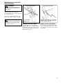
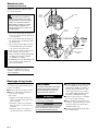
Engine Cover
Screws
Engine Cover
0XIÀHU
0XIÀHU*DVNHW
0XIÀHU%ROWV
Spark Arrester Screen
Spark Arrester Cover
Cover Screws
18
Whenever the unit will not be used for 30
days or longer, use the following proce-
dures to prepare it for storage:
Clean external parts thoroughly.
Ŷ
Drain all the fuel from the carburetor Ŷ
and the fuel tank.
To do so:
Prime the primer bulb until no more 1.
fuel is passing through.
Start and run the engine until it 2.
stops running.
Repeat steps 1 and 2 until the engine 3.
will no longer start.
Long Term Storage
Remove the spark plug and pour about Ŷ
7 mL (.25 oz.) of 2-cycle mixing oil into
the cylinder through the spark plug
hole. Slowly pull the recoil starter 2 or 3
times so oil will evenly coat the interior
of the engine. Reinstall the spark plug.
Before storing the unit, repair or
Ŷ
replace any worn or damaged parts.
Remove the air cleaner element from
Ŷ
the carburetor and clean it thoroughly
with soap and water, let dry and reas-
semble the element.
Store the unit in a clean, dust-free area.
Ŷ
IMPORTANT!
All stored fuels should be stabilized with a
fuel stabilizer such as STA-BIL.
CAUTION!
Gasoline stored in the carburetor for
extended periods can cause hard start-
ing, and could also lead to increased
service and maintenance costs.
0XIÁHUDQGVSDUNDUUHVWHUPDLQWHQDQFH
NOTE
Damage caused by stale or contaminated
fuel is not covered by the Shindaiwa war-
ranty policy.
With a 3 mm hex wrench remove the 1.
engine cover screws and the engine
cover.
If the engine becomes sluggish and low
on power, check and clean the spark
arrester screen.
IMPORTANT!
If you note excessive carbon buildup, con-
sult with an authorized servicing dealer.
WARNING!
Never operate the unit with a
GDPDJHRUPLVVLQJPXIÀHURUVSDUN
arrester! Operating with a missing or
GDPDJHGVSDUNDUUHVWHULVD¿UHKD]DUG
and could also damage your hearing.
With a 4 mm hex wrench, remove the 3 2.
muffler bolts and the muffler.
With a small flat bladed screwdriver 3.
remove the 2 screws holding the
spark arrester screen and cover to the
muffler.
Remove the screen and clean it with a 4.
stiff bristle brush.
Inspect the cylinder exhaust port for 5.
any carbon buildup.
Reassemble the spark arrester, muffler 6.
and engine cover in the reverse order
of disassembly.
Maintenance (continued)

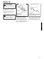
WARNING!
Sharpen only the cutting teeth
of a blade. DO NOT alter the contour
of the blade in any way.
WARNING!
Wear protective gloves when
handling or performing maintenance
on the blade.
Round
File
Round
File
When the cutting edges of the blade
become dull, they can be resharpened with
a few strokes of a file.
In order to keep the blade in balance, all
cutting edges must be sharpened equally.
Shindaiwa Tornado™ Blade
To sharpen the cutters on a Shindaiwa
Tornado™ Blade, use a 7/32-inch round
file. File the leading edge of each tooth to
a razor edge. The top plate of each tooth
should angle back 30°.
Multiple-tooth Circular Blade
Use a round file to maintain a radius of 0.04
to 1 to 1.5 mm (0.06”) at the base of each
tooth. Cutting edges must be offset equally
on each side.
The top plate of each
tooth should angle
back 30°
Maintain a radius of 0.04 to 1 to 1.5 mm (0.06”)
at the base of each tooth. Cutting edges must
be offset equally on each side
Shindaiwa Tornado™ Blade
Multiple-tooth Circular Blade
19
Maintenance (continued)
Blade Sharpening

20
NO
NO
NO
NO
NO
YES
YES
YES
YES
YES
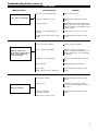
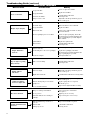
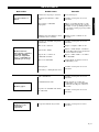
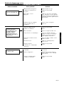
Troubleshooting Guide
Does the engine crank?
Good compression?
Does the tank contain
fresh fuel of the proper
grade?
Is fuel visible and moving
in the return line when
priming?
Is there spark at the spark
plug wire terminal?
Check the spark plug.
The plug is damaged internally or of the
wrong size.
What To Check Possible Cause Remedy
ENGINE DOES NOT START
Faulty recoil starter.
Fluid in the crankcase.
Internal damage.
Loose spark plug.
Excess wear on cylinder, piston,
rings.
Fuel incorrect, stale, or contaminated;
mixture incorrect.
Check for clogged fuel filter and/
or vent.
The ignition switch is in “O” (OFF)
position.
Shorted ignition ground.
Faulty ignition unit.
If the plug is wet, excess fuel may be in
the cylinder.
The plug is fouled or improperly gapped.
Consult with an authorized servicing
dealer.
Tighten and re-test.
Consult with an authorized servicing
dealer.
Refill with fresh, clean unleaded gasoline
with a pump octane of 87 or higher
mixed with a premium 2-cycle mixing oil
or with an equivalent high quality 2-cycle
mixing oil.
Replace fuel filter or vent as required.
Restart.
Move switch to “I” (ON) position and
restart.
Consult with an authorized servicing
dealer.
Crank the engine with the plug removed,
reinstall the plug, and restart.
Clean the spark plug. Check the
Specifications section for the correct plug
and gap for your unit. Restart.
Replace the spark plug. Check the
Specifications section for the correct plug
and gap for your unit. Restart.
La page charge ...
La page charge ...
La page charge ...
La page charge ...
La page charge ...
La page charge ...
La page charge ...
La page charge ...
La page charge ...
La page charge ...
La page charge ...
La page charge ...
La page charge ...
La page charge ...
La page charge ...
La page charge ...
La page charge ...
La page charge ...
La page charge ...
La page charge ...
La page charge ...
La page charge ...
La page charge ...
La page charge ...
La page charge ...
La page charge ...
La page charge ...
La page charge ...
La page charge ...
La page charge ...
La page charge ...
La page charge ...
La page charge ...
La page charge ...
La page charge ...
La page charge ...
La page charge ...
La page charge ...
La page charge ...
La page charge ...
La page charge ...
La page charge ...
La page charge ...
La page charge ...
La page charge ...
La page charge ...
La page charge ...
La page charge ...
La page charge ...
La page charge ...
La page charge ...
La page charge ...
-
 1
1
-
 2
2
-
 3
3
-
 4
4
-
 5
5
-
 6
6
-
 7
7
-
 8
8
-
 9
9
-
 10
10
-
 11
11
-
 12
12
-
 13
13
-
 14
14
-
 15
15
-
 16
16
-
 17
17
-
 18
18
-
 19
19
-
 20
20
-
 21
21
-
 22
22
-
 23
23
-
 24
24
-
 25
25
-
 26
26
-
 27
27
-
 28
28
-
 29
29
-
 30
30
-
 31
31
-
 32
32
-
 33
33
-
 34
34
-
 35
35
-
 36
36
-
 37
37
-
 38
38
-
 39
39
-
 40
40
-
 41
41
-
 42
42
-
 43
43
-
 44
44
-
 45
45
-
 46
46
-
 47
47
-
 48
48
-
 49
49
-
 50
50
-
 51
51
-
 52
52
-
 53
53
-
 54
54
-
 55
55
-
 56
56
-
 57
57
-
 58
58
-
 59
59
-
 60
60
-
 61
61
-
 62
62
-
 63
63
-
 64
64
-
 65
65
-
 66
66
-
 67
67
-
 68
68
-
 69
69
-
 70
70
-
 71
71
-
 72
72


Shindaiwa 89301 Manuel utilisateur
- Catégorie
- Coupe-herbe
- Taper
- Manuel utilisateur
- Ce manuel convient également à
dans d''autres langues
- English: Shindaiwa 89301 User manual
- español: Shindaiwa 89301 Manual de usuario
Documents connexes
-
Shindaiwa C3410/EVC Manuel utilisateur
-
Shindaiwa T2510X/EVC Manuel utilisateur
-
-
-
-
-
-
-
-