Create Windlight Fold DC Manuel utilisateur
- Taper
- Manuel utilisateur

WIND FOLD
CEILING FAN WITH DC MOTOR
VENTILADOR DE TECHO CON MOTOR DC
USER MANUAL


4
INDEX
ENGLISH
LIST OF PARTS 6
INSTALLATION PREPARATION 7
INSTALLATION INSTRUCTIONS 7
SAFETY INSTRUCTIONS 7
DOWNROD INSTALLATION 8
FIXING THE MOUNTING BRACKET 8
ASEMBLING AND HANGING THE FAN 9
REMOTE CONTROL 9
REMOTE CONTROL CONNECTION 10
REMOTE CONTROL RECEIVER PLACEMENT 10
CANOPY ASSEMBLY 10
BLADES ASSEMBLY 11
CONNECTIONS PANEL ASSEMBLY 11
DECORATIVE COVER ASSEMBLY 12
CEILING FAN WITH LED LIGHT 12
ESPAÑOL
LISTA DE PARTES 13
PREPARACIÓN DE LA INSTALACIÓN 14
INSTRUCCIONES DE SEGURIDAD 14
INSTRUCCIONES DE INSTALACIÓN 14
INSTALACIÓN DE LA TIJA 15
FIJACIÓN DEL SOPORTE DE MONTAJE 15
MONTAR Y COLGAR EL VENTILADOR 16
MANDO A DISTANCIA 16
CONEXIÓN DE CONTROL REMOTO 17
COLOCACIÓN DEL RECEPTOR 17
MONTAJE DEL FLORÓN 17
MONTAJE DE LAS ASPAS 18
ENSAMBLAJE DEL PANEL DE CONEXIONES 18
PANEL LED Y PANTALLA DECORATIVA 19
VENTILADOR DE TECHO CON LUZ LED 19
PORTUGUÊS
LISTA DE PEÇAS 20
PREPARAÇÃO DE INSTALAÇÃO 21
INSTRUÇÕES DE SEGURANÇA 21
INSTRUÇÕES DE INSTALAÇÃO 21
INSTALANDO A BARRA DE SUSPENSÃO 22
FIXAÇAO DO SUPORTE DE MONTAGEM 22
MONTAGEM E PENDURA DO VENTILADOR 23
CONTROLE REMOTO 23
CONEXÃO DE CONTROLE REMOTO 24
COLOCAÇÃO DO RECEPTOR 24
MONTAGEM DO CANOPLA 24
MONTAGEM DAS PÁS 25
MONTAGEM DO PATCH PAINEL 25
PAINEL LED E TELA DECORATIVA 26
VENTILADOR DE TETO COM LUZ LED 26
FRANÇAIS
LISTE DES PIÈCES 27
PRÉPARATION DE L'INSTALLATION 28
CONSIGNES D'INSTALLATION 28
CONSIGNES DE SÉCURITÉ 28
PREPARATION DE L’INSTALLATION 29
INSTALLATION DE LA BARRE DE SUSPENSION 29
MONTAGE ET SUSPENSION DU VENTILATEUR 30
TÉLÉCOMMANDE 30
CONNEXION DE LA TÉLÉCOMMANDE 31
EMPLACEMENT DU RÉCEPTEUR 31
ASSEMBLAGE DE FLEURS 31
MONTAGE DES LAMES 32
ASSEMBLAGE DU PANNEAU CONNECTIONS 32
PANNEAU LED ET ÉCRAN DÉCORATIF 33
VENTILATEUR DE PLAFOND AVEC LUMIÈRE LED 33
WIND FOLD

5
DEUTSCH
LISTE DER TEILE 41
INSTALLATIONSVORBEREITUNG 42
SICHERHEITSHINWEISE 42
INSTALLATIONSANLEITUNG 42
NACH DER INSTALLATION 43
STANDORT DES EMPFÄNGERS 43
MONTAGE UND HÄNGE DES LÜFTERS 44
FERNBEDIENUNG 44
ANSCHLUSS DER FERNBEDIENUNG 45
STANDORT DES EMPFÄNGERS 45
BLUMENMONTAGE 45
MONTAGE DER KLINGEN 46
MONTAGE DES CONNECTIONS-PANELS 46
LED PANEL UND DES DEKORATIVEN BILDSCHIRMS 47
DECKENLÜFTER MIT LED-BELEUCHTUNG 47
NEDERLANDS
LIJST MET ONDERDELEN 48
INSTALLATIE VOORBEREIDING 49
BEVEILIGINGSINSTRUCTIES 49
INSTALLATIE INSTRUCTIES 49
NA INSTALLATIE 50
DE MONTAGEBEUGEL BEVESTIGEN 50
DE VENTILATOR MONTEREN EN OPHANGEN 51
AFSTANDSBEDIENING 51
AANSLUITING AFSTANDSBEDIENING 52
PLAATSING ONTVANGER AFSTANDSBEDIENING 52
BLOEMEN ASSEMBLAGE 52
DE MESSEN MONTEREN 53
HET CONNECTIONS-PANEEL MONTEREN 53
LED-PANEEL EN DECORATIEF SCHERM 54
PLAFONDVENTILATOR MET LED-LICHT 54
POLSKI
LISTA CZĘŚCI 55
PRZYGOTOWANIE INSTALACJI 56
INSTRUKCJE BEZPIECZEŃSTWA 56
INSTRUKCJE INSTALACJI 56
PO INSTALACJI 57
MOCOWANIE WSPORNIKA MONTAŻOWEGO 57
MONTAŻ I ZAWIESZANIE WENTYLATORA 58
ZDALNE STEROWANIE 58
POŁĄCZENIE ZDALNEGO STEROWANIA 59
UMIESZCZENIE ODBIORNIKA 59
MONTAŻ KWIATÓW 59
MONTAŻ NOŻY 60
MONTAŻ PANELU CONNECTIONS 60
PANEL LED I EKRAN DEKORACYJNY 61
WENTYLATOR SUFITOWY Z OŚWIETLENIEM LED 61
ITALIANO
ELENCO DELLE PARTI 34
PREPARAZIONE DELL'INSTALLAZIONE 35
ISTRUZIONI PER L'INSTALLAZIONE 35
ISTRUZIONI DI SICUREZZA 35
POST INSTALLAZIONE 36
FISSAGGIO DELLA STAFFA DI MONTAGGIO 36
MONTAGGIO E APPENDERE IL VENTILATORE 37
TELECOMANDO 37
CONNESSIONE TELECOMANDO 38
POSIZIONAMENTO DEL RICEVITORE 38
ASSEMBLAGGIO FIORE 38
MONTAGGIO PALE 39
ASSEMBLAGGIO DEL PANNELLO CONNESSIONI 39
PANNELLO LED E SCHERMO DECORATIVO 40
VENTILATORE DA SOFFITTO CON LUCE LED 40
INDEX
WIND FOLD

6ENGLISH
Thank you for choosing our ceiling fan. Before using the appliance, and to ensure the best
use, please read these instructions carefully.
The safety precautions included in this document reduce the risk of death, injury, and
electric shock when properly followed. Keep the manual in a safe place for future reference,
along with the complete warranty card, sales receipt, and package. If applicable, please
forward these instructions to the next owner of the appliance. Always follow basic safety
precautions and accident prevention measures when using an electrical appliance. We do
not assume any responsibility for the breach of these requirements by the customer.
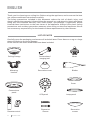
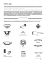
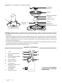
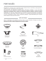
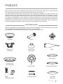
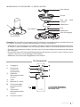
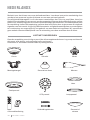
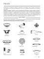
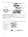
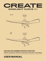
LIST OF PARTS
Carefully open the packaging and remove all included items. Place them on a rug or a large
piece of plastic to avoid any damage.
Check that all the items listed below have been included.
Remote control
Expansion
Screws
Blades
Ceiling Canopy Downrod and
hanging ball
Mounting
bracket
Decorative cover
Motor
Connections
panel LED panel
Decorative
screen
Cover
Lamp panel
ENGLISH

7
ENGLISH
SAFETY INSTRUCTIONS
INSTALLATION INSTRUCTIONS
• When using any electrical appliance, basic safety precautions should always be observed.
• Read this entire manual carefully before beginning installation. Save these instructions.
• Use only original spare parts.
• To reduce the risk of personal injury, connect the fan directly to the building support struc-
ture in accordance with these instructions and use only the supplied hardware.
• To avoid possible electrical shock, before installing your fan, disconnect power by turning
off the circuit breakers in the outlet box and the associated wall switch location. If you
cannot lock the circuit breakers in the off position, securely attach a prominent warning
device, such as a tag, to the service panel.
• All wiring must be in accordance with national and local electrical codes and ANSI / NFPA
70. If you are unfamiliar with wiring, contact a qualied electrician.
• To reduce the risk of personal injury, do not bend the blade clamping system when install-
ing, balancing, or cleaning the fan.
• Never insert foreign objects between the rotating fan blades.
• To reduce the risk of re, electric shock, or motor damage, do not use a solid state speed
control with this fan. Use only original speed controls.
• This appliance can be used by children from 8 years of age and by people with reduced
physical, sensory or mental capacities or lack of experience and knowledge if they have
received supervision or instructions on how to use the appliance safely and understand the
dangers involved. Children must not play with the appliance. Children should not perform
cleaning or maintenance unless they are over 8 years old and supervised. Close supervision
is necessary when any appliance is used by or near children.
NOTE: The important safety precautions and instructions in the manual are not intended
to cover all possible conditions and situations that may occur. It should be understood that
common sense and caution are necessary factors in the installation and operation of this
fan.
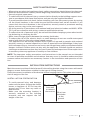
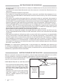
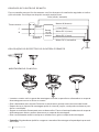
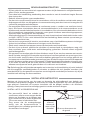
Mark the correct position of the holes and x the ceiling bracket using the screws with metal
plugs or screws and washers suitable for the type of ceiling chosen.
Check the correct installation of the bracket before hanging the fan. This plate must support
the full weight of the fan.
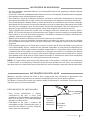
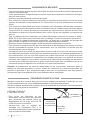
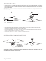
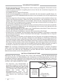
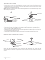
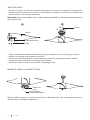
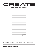
• To avoid personal injury and damage,
make sure the place to hang the sheets
leaves a clearance of 2.3 m from the
ground and 76 cm from any walls or
obstructions.
• Make sure the mounting bracket is
securely attached to the building
structure and can support the full
weight of the fan.
INSTALLATION PREPARATION
76 cm
from wall
or nearest
obstruction. 2.3 m from
the blades
to the
ground.

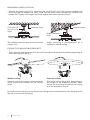
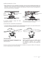
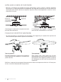
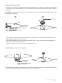
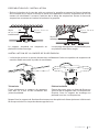
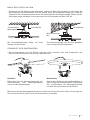
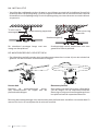
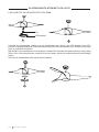
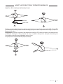
8ENGLISH
20°
Support brace
Standard
mounting
style.
Support brace
Angle mounting
style.
• The outlet box and beam must be securely mounted and capable of reliably supporting at
least the weight of the fan.
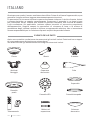
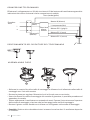
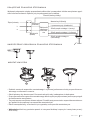
FIXING THE MOUNTING BRACKET
Wooden ceiling
Securely attach the mounting bracket with
wood screws and washers to the ceiling
joints.
Concrete ceiling
Drill holes with an 8mm drill, depending on
the length of the expansion screws. Next,
secure the mounting bracket to the ceiling
with the expansion screws.
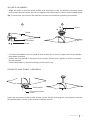
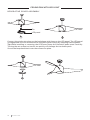
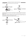
• Remove the seat post bolt by removing the pin and pass the nial (crown molding) and
hood through the hanger bar. Next, route the fan motor wires through the inside of the
hanger bar. Tighten the hanger bar to the engine and insert the bolt and pin.
DOWNROD INSTALLATION
The standard mount hangs from the ceiling
using a rod.
Angle mounting is recommended for a
vaulted or angled ceiling.
Do not x the mounting bracket directly on ceilings with a thickness less than 10mm to avoid
the risk of the screw loosening.

9
ENGLISH
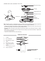
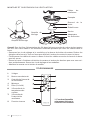
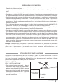
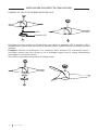
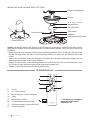
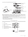
ASEMBLING AND HANGING THE FAN
Electrical wiring
Canopy
Hanging ball slot
Decorative cover
Bolt
Cotter pin Adapter
Fixing screw
Cotter pin
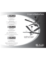
1. **Light
2. On / off button
3. Fan intensity control
4. Timer
5. Batteries (2 x AAA)
6. **Color temperature
control
7. **Fan intensity control
8. Inverse function
REMOTE CONTROL
** Function only available
when the LED board is
installed.
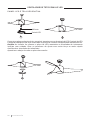
Tip: To make it easier to feed the wires into the bar, wrap some electrical tape around the
wires. This will help you hold them together as you insert them into the bar.
• Loosen set screws and washer on top of motor housing. Remove the pins from the bar (if
you haven't already). Insert the rosette through the bar.
• Pass the cables through the bar and pull the excess cables from the top of the bar to tight-
en them.
• Place the bar inside the motor housing and insert the pins you removed earlier. Tighten the
set screws and washers.
• Lower the rosette onto the motor housing.

10 ENGLISH
CANOPY ASSEMBLY
1
2
3
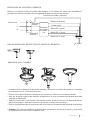
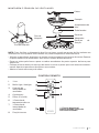
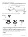
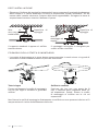
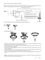
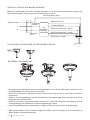
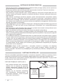
REMOTE CONTROL CONNECTION
REMOTE CONTROL RECEIVER PLACEMENT
Make the connection between the receiver wires and the fan motor wires following the color
indications. Make sure the connection is rm.
DC motor L (red)
Remote
control
receiver
Ground wire
L
N
L input
(black)
Input N
(white)
Neutral N (white)
L clear (blue)
DC motor L (pink)
DC motor L (gray)
Ground wire (green / yellow)
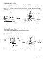
• Raise the rosette up to the mounting bracket and align the loosened screws in the mount-
ing bracket with the holes in the rosette.
• Rotate the n to adjust. Reinsert the screws and secure with a screwdriver.
• Once you have the mounting bracket secured to the junction box you can proceed to hang
the fan.
• Hold the fan rmly with both hands. Pass the rod through the mounting bracket opening
and let the ball rest on the mounting bracket.
• Rotate the ball coupling until it lines up with the tab on the mounting bracket.
• Tip: Someone else should help you hold the ladder and hand you the fan after you get on it.

11
ENGLISH
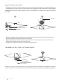
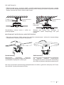
BLADES ASSEMBLY
• Align the holes in the fan blade holder with the holes in the fan blades and motor body
and screw them into place, but do not tighten until they are all in place and screwed down.
Tip: To save time, you can put the washers on each screw before installing the blades.
• Lock the fan blade to the iron plate A with screws. Do not lock it tightly until three blades
have been attached.
• Fasten the iron plate B to the motor with screws. Do not lock it tightly until all iron plates
B are attached.
• Install the blades on the motor and go to the next step.
1 2
Screw
Iron sheet
Blade
Screw
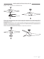
Hook the connection plate to the bottom of the fan by inserting the screw heads into the
designated holes. Screw in the screws and then secure.
CONNECTIONS PANEL ASSEMBLY
Patch panel
Connection panel
screw

12 ENGLISH
Connect the single-pin plugs on the backplane with those on the LED panel. The LED panel
is magnetized so it will be attached to the patch panel simply by snapping them together.
Tip: While installing or removing the LED board, keep the insulation pads intact carefully.
Turning the set screws too hard or too quickly will damage the insulation pads.
Screw the lampshade back onto the connection plate.
CEILING FAN WITH LED LIGHT
DECORATIVE COVER ASSEMBLY
Pin
LED panel
12
3

13
ESPAÑOL
Gracias por elegir nuestro ventilador de techo. Antes de utilizar el aparato, y para garantizar
el mejor uso, lea atentamente estas instrucciones.
Las precauciones de seguridad incluidas en este documento reducen el riesgo de muerte,
lesiones y descargas eléctricas cuando se cumplen correctamente. Guarde el manual en un
lugar seguro para futuras consultas, junto con la tarjeta de garantía completa, el recibo de
compra y el paquete. Si corresponde, transmita estas instrucciones al próximo propietario
del aparato. Siga siempre las precauciones básicas de seguridad y las medidas de prevención
de accidentes cuando utilice un aparato eléctrico. No asumimos ninguna responsabilidad
por el incumplimiento de estos requisitos por parte del cliente.
ESPAÑOL
LISTA DE PARTES
Abra con cuidado el embalaje y retire todos los elementos incluidos. Colócalos sobre una
alfombra o un gran trozo de plástico para evitar cualquier daño.
Compruebe que se hayan incluido todos los elementos que se enumeran a continuación.
Mando a distancia
Tornillos de
expansión
Aspas
Florón Tija
Soporte de
montaje
Cubierta decorativa
Motor
Panel de
conexiones Panel LED
Pantalla
decorativa
Cubierta
Panel de la lámpara

14 ESPAÑOL
INSTRUCCIONES DE SEGURIDAD
INSTRUCCIONES DE INSTALACIÓN
• Al utilizar cualquier aparato eléctrico, siempre se deben observar las precauciones básicas
de seguridad.
• Lea todo este manual detenidamente antes de comenzar la instalación. Guarde estas ins-
trucciones.
• Utilice únicamente repuestos originales.
• Para reducir el riesgo de lesiones personales, conecte el ventilador directamente a la es-
tructura de soporte del edicio de acuerdo con estas instrucciones y use solo el hardware
suministrado.
• Para evitar una posible descarga eléctrica, antes de instalar su ventilador, desconecte la
energía apagando los disyuntores de la caja de salida y la ubicación del interruptor de pa-
red asociado. Si no puede bloquear los disyuntores en la posición de apagado, sujete rme-
mente un dispositivo de advertencia prominente, como una etiqueta, al panel de servicio.
• Todo el cableado debe estar de acuerdo con los códigos eléctricos nacionales y locales y
con ANSI / NFPA 70. Si no está familiarizado con el cableado, contacte con un electricista
cualicado. Para reducir el riesgo de lesiones personales, no doble el sistema de sujeción
de las aspas al instalar, equilibrar o limpiar el ventilador.
• Nunca inserte objetos extraños entre las aspas giratorias del ventilador.
• Para reducir el riesgo de incendio, descarga eléctrica o daños al motor, no utilice un con-
trol de velocidad de estado sólido con este ventilador. Utilice solo controles de velocidad
originales.
• Este aparato puede ser utilizado por niños a partir de 8 años y personas con capacidades
físicas, sensoriales o mentales reducidas o con falta de experiencia y conocimiento si han
recibido supervisión o instrucciones sobre el uso del aparato de forma segura y compren-
den las peligros involucrados. Los niños no deben jugar con el aparato. Los niños no deben
realizar la limpieza ni el mantenimiento, a menos que sean mayores de 8 años y estén su-
pervisados. Es necesaria una estrecha supervisión cuando cualquier aparato sea utilizado
por niños o cerca de ellos.
Consejo: Las importantes precauciones e instrucciones de seguridad que aparecen en
el manual no pretenden cubrir todas las posibles condiciones y situaciones que pueden
ocurrir. Debe entenderse que el sentido común y la precaución son factores necesarios en la
instalación y operación de este ventilador.
Marcar la posición correcta de los oricios y jar el soporte de techo mediante los tornillos
con taco metálico o tornillos y arandelas adecuados al tipo de techo elegido.
Verique la correcta instalación del soporte antes de colgar el ventilador. Esta placa debe
soportar todo el peso del ventilador.
• Para evitar lesiones personales y daños,
asegúrese de que el lugar para colgar
las hojas deje un espacio libre de 2,3 m
del suelo y 76 cm de cualquier pared u
obstrucción.
• Asegúrese de que el soporte de montaje
esté bien sujeto a la estructura del
edicio y pueda soportar todo el peso
del ventilador.
PREPARACIÓN DE LA INSTALACIÓN
76 cm de
separación
entre la
pared u
obstáculo. 2,3 m de
las aspas
al suelo.

15
ESPAÑOL
20°
Supercie de
apoyo.
Estilo de
montaje
tradicional.
Supercie de
apoyo.
Estilo de montaje
en ángulo.
• La caja de salida y la viga deben estar montadas de forma segura y ser capaces de soportar
de manera conable al menos el peso del ventilador.
FIJACIÓN DEL SOPORTE DE MONTAJE
Techo de madera
Fije rmemente el soporte de montaje con
tornillos para madera y arandelas a las
juntas del techo.
Techo de hormigón
Realice agujeros con un taladro de 8
mm, según la longitud de los tornillos
de expansión. Después, je el soporte
de montaje al techo con los tornillos de
expansión.
• Quite el perno de la tija, quitando el pasador y pase el orón (moldura del techo) y la
capota del motor a través de la barra de suspensión. Luego, pase los cables del motor del
ventilador a través del interior de la barra de suspensión. Apriete la barra de suspensión al
motor e inserte el perno y el pasador.
INSTALACIÓN DE LA TIJA
El montaje estándar cuelga del techo
mediante una varilla.
Se recomienda el montaje en ángulo para
un techo abovedado o en ángulo.
No je el soporte de montaje directamente en techos con un grosor inferior a 10 mm para
evitar el riesgo de que el tornillo se aoje.

16 ESPAÑOL
MONTAR Y COLGAR EL VENTILADOR
Cableado
eléctrico
Florón
Ranura para bola
colgante
Embellecedor
Tornillo
Pasador de
bloqueo Adaptador
Tornillo de jación
Pasador de bloqueo
1. **Luz
2. Botón de encendido/
apagado
3. Control de intensidad
del ventilador
4. Temporizador
5. Pilas (2 x AAA)
6. **Control de
temperatura de color
7. **Control de
intensidad del
ventilador
8. Función inversa
MANDO A DISTANCIA
** Función solo disponible
cuando se tiene instalada
la placa LED.
Consejo: Para facilitar la introducción de los cables en la barra, coloque un poco de cinta
aislante alrededor de los cables. Esto le ayudará a mantenerlos juntos mientras los inserta
en la barra.
• Aoje los tornillos de jación y la arandela de la parte superior de la carcasa del motor.
Retire los pasadores de la barra (si no lo ha hecho aún). Introduzca el orón por la barra.
• Pase los cables por la barra y tire del sobrante de los cables desde la parte superior de
la barra para ajustarlos.
• Coloque la barra dentro de la carcasa del motor e inserte los pasadores que retiró ante-
riormente. Ajuste los tornillos de jación y las arandelas.
• Baje el orón hacia la carcasa del motor.

17
ESPAÑOL
MONTAJE DEL FLORÓN
1
2
3
CONEXIÓN DE CONTROL REMOTO
COLOCACIÓN DEL RECEPTOR DE CONTROL REMOTO
Realice la conexión entre los cables del receptor y los cables del motor del ventilador si-
guiendo las indicaciones de color. Asegúrese de que la conexión esté rme.
Motor DC L (rojo)
Receptor
del mando
a distan-
cia
Toma tierra
L
N
Entrada L
(negro)
Entrada N
(blanco)
Neutro N (blanco)
L claro (azul)
Motor DC L (rosa)
Motor DC L (gris)
Toma tierra (verde / amarillo)
• Levante el orón hasta el soporte de montaje y alinee los tornillos aojados en el soporte
de montaje con los oricios del orón.
• Gire el orón para ajustarlo. Reinserte los tornillos y fíjelos con un destornillador.
• Una vez tenga el soporte de montaje asegurado a la caja de conexiones puede proceder
a colgar el ventilador.
• Agarre el ventilador con rmeza con ambas manos. Pase la barra por la apertura del so-
porte de montaje y deje que la bola se apoye en el soporte de montaje.
• Gire el acoplamiento de la bola hasta que se alinee con la pestaña del soporte de montaje.
• Consejo: Otra persona debería ayudarle para sostener la escalera de mano y alcanzarle
el ventilador una vez se haya subido a esta.

18 ESPAÑOL
MONTAJE DE LAS ASPAS
• Alinee los oricios del porta aspas con los oricios de las aspas y el cuerpo del motor y
atorníllelos en su lugar, pero no los apriete hasta que estén todos colocados y atornillados.
Consejo: Para ahorrar tiempo, puede colocar las arandelas en cada tornillo antes de instalar
las hojas.
• Bloquee la paleta del ventilador en la chapa de hierro A con tornillos. No lo bloquee con
fuerza hasta que se hayan jado tres cuchillas.
• Sujete la chapa de hierro B al motor con tornillos. No lo bloquee con fuerza hasta que
todas las planchas de hierro B estén jadas.
• Instale las cuchillas en el motor y vaya al siguiente paso.
1 2
Tornillo
Chapa de hierro
Aspa
Tornillo
Enganche la placa de conexiones a la parte inferior del ventilador insertando las cabezas
de los tornillo en los oricios destinados a ello. Enrosque los tornillos y después asegúrelo.
ENSAMBLAJE DEL PANEL DE CONEXIONES
Panel de
conexiones
Tornillo del panel de
conexiones

19
ESPAÑOL
Conecte los enchufes de un solo pin de la placa de conexiones con los del panel LED. El
panel LED está magnetizado, por lo que se adjuntará al panel de conexiones simplemente
colocándolos juntos.
Consejo: Mientras instala o retira la placa de LED, mantenga las almohadillas de aislamiento
intactas con cuidado. Si gira los tornillos de jación con demasiada fuerza o rápidamente, se
dañarán las almohadillas de aislamiento.
Vuelva a atornillar la pantalla de la lámpara a la placa de conexiones.
VENTILADOR DE TECHO CON LUZ LED
PANEL LED Y PANTALLA DECORATIVA
Pin
Panel LED
12
3

20 PORTUGUÊS
Obrigado por escolher nosso ventilador de teto. Antes de usar o aparelho, e para garantir o
melhor uso, leia atentamente estas instruções.
As precauções de segurança incluídas neste documento reduzem o risco de morte,
ferimentos e choque elétrico quando devidamente seguidas. Guarde o manual em local
seguro para referência futura, junto com o cartão de garantia completo, recibo de venda e
embalagem. Se aplicável, encaminhe estas instruções ao próximo proprietário do aparelho.
Sempre siga as precauções básicas de segurança e as medidas de prevenção de acidentes
ao usar um aparelho elétrico. Não assumimos qualquer responsabilidade pela violação
destes requisitos por parte do cliente.
PORTUGUÊS
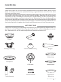
LISTA DE PEÇAS
Abra a embalagem com cuidado e remova todos os itens incluídos. Coloque-os sobre um
tapete ou um pedaço grande de plástico para evitar danos.
Verique se todos os itens listados abaixo foram incluídos.
Controle remoto
Parafusos de
expansão
Pás
Canopla Barra
Suporte de
montagem
Capa decorativa
Motor
Painel de
remendo Painel de
LED
Tampa
decorativa
Cobrir
Painel de lâmpada
La page charge ...
La page charge ...
La page charge ...
La page charge ...
La page charge ...
La page charge ...
La page charge ...
La page charge ...
La page charge ...
La page charge ...
La page charge ...
La page charge ...
La page charge ...
La page charge ...
La page charge ...
La page charge ...
La page charge ...
La page charge ...
La page charge ...
La page charge ...
La page charge ...
La page charge ...
La page charge ...
La page charge ...
La page charge ...
La page charge ...
La page charge ...
La page charge ...
La page charge ...
La page charge ...
La page charge ...
La page charge ...
La page charge ...
La page charge ...
La page charge ...
La page charge ...
La page charge ...
La page charge ...
La page charge ...
La page charge ...
La page charge ...
La page charge ...
La page charge ...
La page charge ...
-
 1
1
-
 2
2
-
 3
3
-
 4
4
-
 5
5
-
 6
6
-
 7
7
-
 8
8
-
 9
9
-
 10
10
-
 11
11
-
 12
12
-
 13
13
-
 14
14
-
 15
15
-
 16
16
-
 17
17
-
 18
18
-
 19
19
-
 20
20
-
 21
21
-
 22
22
-
 23
23
-
 24
24
-
 25
25
-
 26
26
-
 27
27
-
 28
28
-
 29
29
-
 30
30
-
 31
31
-
 32
32
-
 33
33
-
 34
34
-
 35
35
-
 36
36
-
 37
37
-
 38
38
-
 39
39
-
 40
40
-
 41
41
-
 42
42
-
 43
43
-
 44
44
-
 45
45
-
 46
46
-
 47
47
-
 48
48
-
 49
49
-
 50
50
-
 51
51
-
 52
52
-
 53
53
-
 54
54
-
 55
55
-
 56
56
-
 57
57
-
 58
58
-
 59
59
-
 60
60
-
 61
61
-
 62
62
-
 63
63
-
 64
64


Create Windlight Fold DC Manuel utilisateur
- Taper
- Manuel utilisateur
dans d''autres langues
- italiano: Create Windlight Fold DC Manuale utente
- español: Create Windlight Fold DC Manual de usuario
- Deutsch: Create Windlight Fold DC Benutzerhandbuch
- Nederlands: Create Windlight Fold DC Handleiding
- português: Create Windlight Fold DC Manual do usuário
- polski: Create Windlight Fold DC Instrukcja obsługi
Documents connexes
-
Create WINDLIGHT Manuel utilisateur
-
 Create Wind Round Ceiling Fan Manuel utilisateur
-
Create Wind Stylance DC Manuel utilisateur
-
 Create WINDLIGHT CURVE DC Le manuel du propriétaire
-
Create WINDLIGHT EASY Manuel utilisateur
-
-
Create Wind Tube Ceiling Fan Manuel utilisateur
-
Create 150W Manuel utilisateur
-
 Create Electric Tower Rack Manuel utilisateur


Autres documents
-
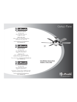
Kichler 300317DBK Manuel utilisateur
-
Progress Lighting P250063-031 Guide d'installation
-
Falcon REF 072228 Installing
-
 Craftmade Argos AG52 Installation Instructions Manual
-
 Craftmade Cameo CB60 Installation Instructions Manual
-
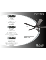 Craftmade Artistry AY56 Installation Instructions Manual
-
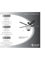 Craftmade Ceylon CY52 Installation Instructions Manual


