Danby DPA080C2SDB Le manuel du propriétaire
- Catégorie
- Climatiseurs mobiles
- Taper
- Le manuel du propriétaire

OWNER’S USE AND CARE GUIDE
GUIDE D’UTILISATION ET D'ENTRETIEN
MODEL • MODÈLE
DANBY PRODUCTS LIMITED, ONTARIO, CANADA N1H 6Z9
DANBY PRODUCTS INC., FINDLAY, OHIO, USA 45840
DPA080C2SDB
PORTABLE AIR CONDITIONER
CLIMATISEUR PORTATIF
2015.01.05

DO NOT RETURN THIS UNIT TO THE RETAILER
WITHOUT FURTHER INSTRUCTIONS
Dear valued customer, we hope your Danby product purchase fulfills all
your requirements. Your satisfaction is our priority!
Please contact us at our toll free consumer service number for any inquiries
you may have about your new unit.
NE PAS RETOURNER CET APPAREIL CHEZ LE
DÉTAILLANT SANS CONSIGNES SUPPLÉMENTAIRES
Cher(ère) client(e) important(e), nous espérons que votre produit Danby
répond à tous vos besoins. Votre satisfaction est notre priorité!
Veuillez nous contacter au numéro gratuit de service après-vente, si
vous avez des questions quelconques à propos de votre nouvel appareil.
NO DEVUELVA ESTA UNIDAD A LA TIENDA SIN
INSTRUCCIONES ADICIONALES
Estimado cliente, esperamos que el producto Danby que ha comprado
satisfaga completamente sus necesidades. Su satisfacción
es nuestra prioridad!
Por favor, contáctenos gratuitamente a nuestro número de Servicio al
Cliente para cualquier pregunta que tenga sobre su nuevo electrodoméstico.
1-800-263-2629
(1-800-26-DANBY)
Danby 28.08.2014

TO OBTAIN WARRANTY SERVICE YOU MUST PROVIDE A VALID PROOF OF
PURCHASE. PLEASE STAPLE YOUR RECEIPT TO THIS PAGE FOR FUTURE
REFERENCE.
POUR OBTENIR LE SERVICE SUR GARANTIE, VOUS DEVEZ FOURNIR UNE
PREUVE D’ACHAT VALIDE. VEUILLEZ AGRAFER VOTRE REÇU À CETTE PAGE
POUR RÉFÉRENCE FUTURE.
This product is factory equipped with a power supply cord that has a three-pronged grounded plug. It must
be plugged into a mating grounding type receptacle in accordance with the National Electrical Code and
applicable local codes and ordinances. If the circuit does not have a grounding type receptacle, it is the
responsibility and obligation of the customer to exchange the existing receptacle in accordance with the
National Electrical Code and applicable local codes and ordinances. The third ground prong should not,
under any circumstances, be cut or removed. Never use the cord, the plug or the appliance when they show
any sign of damage. Do not use your appliance with an extension cord unless it has been checked and test-
ed by a qualifi ed electrician or electrical supplier.
IMPORTANT - GROUNDING METHOD
Ce produit arrive d’origine avec un cordon d’alimentation équipé d’une prise à trois fi ches. Il doit être
branché dans une prise avec une fi che de mise à la terre en conformité avec le Code national de l’électricité
et les codes et règles locaux applicables. Si la prise murale n’a pas de mise à la terre, il est de la
responsabilité et l’obligation du client de changer la prise existante pour la rendre conforme au Code
national de l’électricité et aux codes et règles locaux applicables. La fi che de mise à la terre ne doit pas, en
aucune circonstance, être coupée ou retirée. Si vous apercevez des signes de dommage, n’utilisez jamais le
cordon d’alimentation, la prise ou l’appareil. N’utilisez jamais l’appareil avec une rallonge sauf si elle a été
vérifi ée et testée par un électricien qualifi é ou un fournisseur de matériel électrique.
IMPORTANT - MÉTHODE POUR LA MISE À LA TERRE

PORTABLE AIR CONDITIONER
Owner’s Use and Care Guide .................................
• Welcome
• Important Safety Information
• Features
• Installation Instructions
• Operation Instructions
• Care and Maintenance
• Troubleshooting
• Warranty
CLIMATISEUR PORTATIF
Guide d’utilisation et d’entretien................................
• Bienvenue
• Consignes de sécurité importantes
• Caractéristiques
• Consignes d’installation
• Consignes d’utilisation
• Soins et entretien
• Dépannage
• Garantie
CONTENTS
CAUTION:
Read and follow all safety rules and operating
instructions before fi rst use of this product.
AVERTISSEMENT :
Veuillez lire attentivement les consignes de
sécurité et les instructions d’utilisation avant
l’utilisation initiale de ce produit.
TABLE DES MATIÈRES
Model • Modèle
WARNING
Improper connection of the grounding plug can
result in risk of fi re, electric shock and/or injury to
persons associated with the appliance. Check with
a qualifi ed service representative if in doubt that
the appliance is properly grounded.
AVERTISSEMENT
Une fi che de mise à la terre mal branchée peut
entraîner un risque d’incendie, de choc électrique
ou de blessures aux personnes qui utilisent
l’appareil. Si vous n’êtes pas certain que l’appareil
est correctement mis à la terre, consultez un
préposé du service qualifi é.
1-17
18-34
DPA080C2SDB

Welcome
Welcome to the Danby family. We are proud of our quality products, and we believe in dependable service, like you will
find in this Owner’s Use and Care Guide, and like you will receive from our friendly customer service department. Best
of all, you will experience these values each and every time you use your Danby appliance. That is important, because
your new appliance will be a part of your family for a long time.
Note the information below; you will need this information to obtain service under warranty.
To receive service, you must provide the original receipt.
Serial
Number:
Date of Purchase:
NEED HELP?
Before you call for service, here are a few things you can do to help
us serve you better:
Read this Owner’s Use and Care Guide:
It contains instructions to help you use and maintain your
appliance properly.
If you received a damaged appliance:
Immediately contact the retailer (or builder) that sold you the
appliance.
Save time and money:
Check the Troubleshooting section at the end of the guide before call-
ing. This section helps you solve common problems that may occur.
If you do need service, you can relax, knowing help is only a phone
call away.
1-800-26-
(1-800-263-2629)
1

Important Safety Information
READ AND FOLLOW ALL SAFETY INSTRUCTIONS
To prevent injury to the user or other people and property damage, the following instructions must be
followed. Incorrect operation resulting from ignoring these instructions may cause harm or damage.
SAFETY
PRECAUTIONS
ALWAYS DO THIS
Your air conditioner should be used in such a way that it is protected from
moisture. e.g. condensation, splashed water, etc. Do not place or store
your air conditioner where it can fall or be pulled into water or any other
liquid. Unplug unit immediately if this occurs.
Always transport your air conditioner in a vertical position and place on a
stable, level surface during use. If the unit is transported laying on its side it
should be stood up and left unplugged for 4 hours.
Turn off the unit when not in use.
Always contact a qualifi ed person to perform repairs. If the power cord is
damaged it must be repaired by a qualifi ed technician.
Keep the unit away from walls, furniture and curtains with a clearance of at
least 30 cm all around.
If the air conditioner is knocked over during use, turn off the unit and
unplug it immediately.
Always use the switch on the control panel to turn the unit on or off.
Portable air conditioners exhaust large amounts of room air. Always ensure
an adequate supply of make-up air to operate effi ciently.
NEVER DO THIS
Do not operate your air conditioner in a wet room such as a bathroom or
laundry room.
Do not touch the unit with wet or damp hands.
Do not press the buttons on the control panel with anything other than your
fi ngers.
Do not remove any fi xed components. Never use this appliance if it is not
working properly, or if it has been dropped or damaged.
Never use the plug to start and stop the unit.
Do not cover or obstruct the inlet or outlet grilles.
Do not use hazardous chemicals to clean or come into contact with the unit.
Do not use the unit in the presence of infl ammable substances or vapour
such as alcohol, insecticides, gasoline, etc.
Do not allow children to operate the unit unsupervised.
Do not use this product for functions other than those described in this
instruction manual.
2

Important Safety Information
READ AND FOLLOW ALL SAFETY INSTRUCTIONS
To prevent injury to the user or other people and property damage, the following instructions must be
followed. Incorrect operation resulting from ignoring these instructions may cause harm or damage.
ENERGY SAVING
TIPS
OPERATING
CONDITIONS
TOOLS FOR
WINDOW KIT
INSTALLATION
• Use the unit in the recommended room size.
• Locate the unit where furniture cannot obstruct the air fl ow.
• Keep blinds/curtains closed during the sunniest part of the day.
• Keep the fi lters clean.
• Keep doors and windows closed to keep cool air in and warm air out
(cooling mode)
MODE ROOM TEMPERTURE
Air conditioning 16°C ~ 35°C (61°F ~ 95°F)
The air conditioner must be operated within the temperature range
indicated below:
Note: Performance may be reduced outside of these operating tempera-
tures.
1. Screwdriver (medium size, Phillips)
2. Tape measure or ruler
3. Knife or scissors
4. Saw (In the event that the window kit needs to be cut down in size
because the window is too narrow for direct installation).
See www.danby.com for general instruction guide
3
The power cord supplied with this air conditioner contains a device that senses damage to the power cord. To test if your
power cord is working properly, you must do the following:
1. Connect the power supply cord to an electrical outlet.
2. The power supply cord has two buttons located on the head of the plug. One button is marked “TEST”, and the other
is marked “RESET”. Press the “TEST” button; you will hear a click as the “RESET” button pops out.
3. Press the “RESET” button; you will hear a click as the button engages.
4. The power supply cord is now energized and supplying electricity to the air conditioner (on some products this is also
indicated by a light on the plug head).
NOTE: The power cord supplied with this air conditioner contains a current leakage detection device designed to reduce
the risk of fi re. In the event the power supply cord is damaged, it cannot be repaired and must be replaced with a new
cord from the product manufacturer.
• Under no circumstances should this device be used to turn the unit on or off.
• The “RESET” button must always be pushed in (engaged) for correct operation.
• The power supply cord must be replaced if it fails to reset when the “TEST” button is pushed in.
NOTE: Some plugs have buttons on the top.
POWER SUPPLY CORD
Plug in and press
RESET
TEST
RESET

Identifying Parts
WARNING
• Do not store or use gasoline or other fl ammable vapours and liquids in the vicinity of this or any other
appliance.
• Avoid fi re hazard or electric shock. Do not use an extension cord or an adaptor plug. Do not remove any
prong from the power cord.
ELECTRICAL INFORMATION
WARNING
• Be sure the electrical supply is adequate for the model you have chosen. This information can be found
on the serial plate, which is located on the side of the cabinet and behind the grille.
• Be sure the air conditioner is properly grounded. To minimize shock and fi re hazards, proper grounding
is important. The power cord is equipped with a three-prong grounding plug for protection against
shock hazards.
• Your air conditioner must be used in a properly grounded wall receptacle. If the wall receptacle you
intend to use is not adequately grounded or protected by a time delay fuse or circuit breaker, have a
qualifi ed electrician install the proper receptacle.
• Ensure the receptacle remains accessible after the unit is installed.
4
TABLE 2
Receptacle and Fuse Types
Rated Volts 125
Amps 15
Wall Outlet
Fuse Size 15
Time Delay Fuse Plug Type
(or Circuit Breaker)
TABLE 1
Suggested Individual Branch Circuit
Nameplate Amps
5.9
*AWG Wire Size
14
AWG- American Wire Gauge
*Based on copper wire at 105°C temperature rating
1. All wiring must comply with local and national electrical codes and must be installed by a qualifi ed electrician. If you
have any questions regarding the following instructions, contact a qualifi ed electrician.
2. Check available power supply and resolve any wiring problems BEFORE installing and operating this unit.
3. This 115V air conditioner uses 5.9 or less nameplate amps and may be used in any properly wired, general-purpose
household receptacle. See Table 1 for the specifi cations for the individual branch circuit.
4. For your safety and protection, this unit is grounded through the power cord plug when plugged into a matching wall
outlet. If you are not sure whether your wall outlet is properly grounded, please consult a qualifi ed electrician.
5. The wall outlet must match the 3-prong plug on the service cord supplied with the unit. DO NOT use plug adapters.
See Table 2 for receptacle and fuse information.

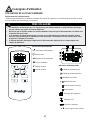
• Ensure that all the accessories are included in the
package and refer to the installation instructions for
their usage.
Note: All the illustrations in this manual are for ex-
planatory purposes only. Your air conditioner may be
slightly different.
Identifying Parts
FEATURES
ACCESSORIES
ELECTRIC SHOCK HAZARD: To avoid the possibility of
personal injury, disconnect power to the unit before installing or
servicing.
Installation Accessories:
• Flexible exhaust hose
• Exhaust nozzle connector (3 pcs) (Connector A, B and C)
• Window door slider kit (3 pcs)
• Screws (5 pcs)
• Pipe Clip
• Pipe Hoop (2)
• Drainage Pipe
• Rubber Plug
• Adhesive foam (2)
• Non-adhesive foam (4)
NOTE: The exhaust / window kit must be installed at all times
when the unit is operating under AIR CONDITIONING mode.
There should be at least 11.8” (30cm) clearance between the
unit and any other objects or building structures, and the unit
should be installed on a level fl oor. The unit does not have
to be vented outside during dehumidifying or fan only mode
operation. When the unit is in dehumidifying mode, the warm
air exhaust must be vented inside the room.
5
1
2
3
4
8
5
6
7
1. Control Panel
2. Air outlet
3. Caster
4. Remote Control Holder
5. Power Cord
6. Air Filter
7. Upper Air Inlet Grill
8. Lower Air Inlet Grill
Exhaust
Connector A
Exhaust
Connector B
Exhaust
Connector C
Window Slider
Kit
Exhaust
Hose
Screw
(5)
Pipe Clip
Pipe Hoop
(2)
Drainage Pipe
Rubber
Plug
Foam (adhesive and
non-adhesive) (6)

Installation Instructions
LOCATION
• The air conditioner should be placed on a fi rm foundation to minimize noise
and vibration. For safe and secure positioning, place the unit on a smooth, level
fl oor strong enough to support the unit.
• The unit has casters to aid placement, but it should only be rolled on smooth,
fl at surfaces. Use caution when rolling on carpeted surfaces. Use caution and
protect fl oors when rolling over wood fl oors. Do not attempt to roll the unit over
objects.
• The unit must be placed within reach of a properly rated grounded socket.
• Never place any obstacles around the air inlet or outlet of the unit.
• Allow at least 30 cm of space away from the wall for effi cient air conditioning.
WINDOW SLIDER KIT
INSTALLATION
NOTE: If the window opening is less than the mentioned minimum length of the
window slider kit, cut the end without the hole in it short enough to fi t in the window
opening. Never cut out the hole in window slider kit (visit www.danby.com for
general instruction videos).
Your window kit has been designed to fi t most “vertical” / “horizontal” windows up
to a maximum height of 80” (203 cm). For vertical window applications, multi lock
positions are provided on the edge of each slider section to secure each sliding
section together.
1. Select a suitable location, making sure you have access to an electrical outlet.
2. Install the fl exible hose to the rear of the unit. Insert the hose collar on top of
the exhaust opening.
3. Install the adjustable Window Slider Kit as required.
4. Install the opposite end of the fl exible exhaust hose into the window exhaust
adapter.
5. Install the window exhaust adapter into the opening in the slider section, mak-
ing sure the window slider sections are secure.
6. Plug the unit into a 115V/60Hz grounded electrical outlet.
6
Adjusting Plate
Cut if needed
Connector C
Width
Height
Screw
Screw

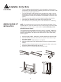
Installation Instructions
INSTALLATION IN A
DOUBLE-HUNG SASH
WINDOW
1. Measure the adhesive foam seal to fi t the windowsill. Then cut the foam seal to
the proper length and attach it to the windowsill.
2. Adjust the length of the window slider kit to fi t the width of the window. Shorten
the adjustable window kit to fi t the width of the window if less than 70 cm (27.6
inches). Open the window sash and place the window slider kit on the window-
sill.
3. Cut the foam seal (adhesive type) to the proper length and attach it on the top
of the window slider kit. Close the window sash securely against the window
slider kit.
4. Cut the foam seal to an appropriate length and seal the open gap between the
top window sash and outer window sash.
Foam seal
(adhesive type)
Foam seal
Windowsill
Window Kit
Windowsill
Window Kit
70 cm - 203 cm
27.6 inches - 80 inches
Foam Seal
7

Installation Instructions
INSTALLATION IN A
SLIDING SASH
WINDOW
1. Measure the adhesive foam seal to fi t the windowsill. Cut the foam seal (adhe-
sive type) to the proper length and attach it to the window frame.
2. Adjust the length of the window slider kit according to the height of the window,
shorten the adjustable window kit if the height of the window slider is less than
70 cm (27.6 inches). Open the window sash and place the window slider kit on
the windowsill.
3. Cut the foam seal (adhesive type) to the proper length and attach it to the top of
the window. Close the sliding sash securely against the window.
4. Cut the foam seal to an appropriate length and seal the open gap between the
top window sash and outer window sash.
Foam seal
(adhesive type)
Window
Kit
Foam
Seal
70 cm - 203 cm
27.6 inches -
80 inches
Foam
Seal
8

Features
ELECTRONIC CONTROL
INSTRUCTIONS
Before you begin, thoroughly familiarize yourself with the control panel and remote control and all its functions. Select the
functions you desire based on the associated symbol.
The unit can be controlled by the control panel alone or with the remote control.
Power Switch: Turns the unit ON/OFF.
Mode: Allows you to scroll through and select desired operating mode.
Temperature Adjust: Used for adjusting the thermostat. The default display is set temperature. In cooling
mode, when or button is pressed, the set temperature is displayed and may be adjusted. Temperature is
only adjustable in cool mode.
LED Display
MODE INDICATOR LIGHTS
Cooling Mode: When cool mode is selected, the indicator light will illuminate. During the cooling mode, the air
is cooled and hot air is exhausted outside through the exhaust tube. Adjust the fan speed to suit your desired
comfort level.
Note: The air exchange hose must vent outside the room when using cool mode.
Dehumidify Mode: When dehumidify mode is selected, the indicator light will illuminate. Air is dehumidifi ed as
it passes through the unit, without being in full cooling mode.
Note: The warm air exchange hose must be vented outside the room when using dehumidifying mode.
Fan Mode: When fan mode is selected, the indicator light will illuminate.
Full Water Tank Indicator Light: Illuminates when the water tank is full.
9

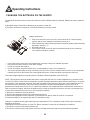
Operating Instructions
Location of the remote control
• Use the remote control within a distance of 8 meters from the appliance, pointing it towards the receiver. Reception is
confi rmed by a beep.
• The air conditioner will not operate if curtains, doors or other materials block the signals from the
remote control to the indoor unit.
• Prevent any liquid from falling into the remote control. Do not expose the remote control to direct
sunlight or heat.
• If the infrared signal receiver on the indoor unit is exposed to direct sunlight, the air conditioner may not
function properly. Use curtains to prevent the sunlight from falling on the receiver.
• If other electrical appliances react to the remote control, either move these appliances or call the service
depot.
CAUTION
REMOTE CONTROL
Control Buttons
Power Button
Mode Button
Temperature Adjustment Buttons
Fan Button
Sleep Button
Timer Button
10
LED Display Indicators
◄ Air Conditioning Mode
◄ Dehumidifying Mode
◄ Fan Mode
► Sleep Mode
Timer on
▲
Timer off
▲
Temperature Display
°C/°F Display
Fan Speed
► Child Lock

1. Power Button: Turns the unit on.
2. Mode Button: Each time the button is pressed, the operation mode changes in the following sequence:
COOL DRY FAN
3. Temperature Adjustment Buttons: Push these buttons to increase or decrease the indoor temperature setting by
1°C (1°F) increments. When the unit setting is on “Timer,” press these buttons to adjust the time. Note: When the unit
is off, the display on the remote will show the set temperature.
4. Fan Button: Used to select the fan speed in four steps:
AUTO
• After selecting, Cool or Fan mode, pressing the fan button will allow you to set your desired fan speed.
5. Sleep Button: Select this function if you want the unit to maintain a comfortable setting and save energy while you
sleep. The temperature setting will increase by 1°C (2°F) over the next hour and by another 1°C (2°F) over another
hour.
Operating Instructions
REMOTE CONTROL
6. Timer Button: When the unit is on, press the timer button to set the “Timer off” function. The “ ” and “.5H” icons
will start fl ashing. Within 5 seconds, press the up and down buttons to adjust the time to indicate when you want the
unit to shut off. Release the button after you have achieved the time you desire. Then press the “timer” button again
to confi rm. The “ ” and “.5H” buttons will stop fl ashing.
When the unit is off, press the timer button to set the “Timer on” function. The “ ” and “.5H” icons will start fl ashing.
Within 5 seconds, press the up and down buttons to adjust the time to indicate when you want the unit to turn on. Re-
lease the button after you have achieved the time you desire. Then press the “timer” button again to confi rm. The
“ ” and “.5H” buttons will stop fl ashing.
Note: Pressing the up or down button will increase or decrease the time by 0.5h, holding the up or down button will
allow you to change the time more rapidly.
To cancel the timer, press the “timer” button once to review the remaining time, within 5 seconds press “Timer” again
to cancel the timer function.
Child Lock Function:
You may lock the remote from being used by pressing the “ ” and “ ” buttons simultaneously on the remote. The lock
indicator will illuminate on the remote display. To turn the lock off, press the “ ” and “ ” buttons simultaneously again.
Note: The Child Lock Function is only available for the remote control. If the child lock is on, the buttons on the units con-
trol panel still function normally.
Note: When the Child Lock is initiated, the unit does not beep to indicate it is locked, the only indicator is the illumination
arrow on the display panel.
Note: (While the unit is OFF) To change the unit from °C to °F, press the “ ” and “ ” button simultaneously.
Note: To turn the LED display on/off, press “
” and simultaneously.
11

Operating Instructions
CHANGING THE BATTERIES ON THE REMOTE
• Protect the remote control from high temperatures, and keep it away from radiation exposure.
• Keep the control panel receiver out of direct sunlight.
• Do not mix old and new batteries.
• Do not mix alkaline, standard (carbon-zinc), or rechargeable (ni-cad, ni-mh,etc) batteries.
• The remote operates within a range of 8 meters (26 ft.) from the receiver located inside the main unit. Any obstruction
between the receiver and remote may cause signal interference, limiting the ability to program the main unit.
This Class B digital apparatus complies with the Canadian ICES-003 standard. CAN ICES-3 (B)
NOTE: This equipment has been tested and found to comply with the limits for a Class B digital device, pursuant to Part
15 of the FCC Rules. These limits are designed to provide reasonable protection against harmful interference in a residen-
tial installation. This equipment generates, uses and can radiate radio frequency energy and, if not installed and used in
accordance with the instructions, may cause harmful interference to radio communications. However, there is no
guarantee that interference will not occur in a particular installation. If this equipment does cause harmful interference to
radio or television reception, which can be determined by turning the equipment off and on, the user is encouraged to try
to correct the interference by one or more of the following measures:
1) Reorient or relocate the receiving antenna.
2) Increase the separation between the equipment and receiver.
3) Connect the equipment into an outlet on a circuit different from that to which the receiver is connected.
4) Consult the dealer or an experienced radio/TV technician for help.
Changes or modifi cations not approved by the party responsible for FCC compliance could void the user’s authority to
operate the equipment.
This appliance complies with Part 15 of the FCC Rules. Operation is subject to the following two conditions:
1) This device may not cause harmful interference.
2) This device must accept any interference received, including interference that may cause undesired operation.
Battery replacement:
1. Push in the tab on the rear cover of the remote and pull off. Continue pulling
(gently) until the cover separates completely from the unit.
2. Insert (2) batteries (AAA) following the same orientation (polarity) depicted inside
the battery chamber (+/-).
3. Re-install rear cover.
4. If the remote control will not be used for extended periods of time (vacations
etc.), batteries should be removed.
To operate the hand-held remote control will require two “AAA” alkaline batteries (included). Batteries should be replaced
when:
a) No signal (beep) is heard when attempting to program the main unit.
b) The main unit does not respond to a command issued by the remote control.
12

Operating Instructions
AIR CONDITIONING
Important: The exhaust hose must be properly vented outdoors during air conditioning mode.
1. Press the POWER SWITCH key
to switch on the unit, and the previous set temperature will be shown in the
temperature display area of the display panel.
2. Press the MODE key
until the COOL indicator light illuminates. Each depression of the MODE key will ad-
vance to a different mode setting (Cool, Dehumidifi er, Fan).
3. Press the appropriate increase or decrease buttons to select a suitable operating temperature setting.
Temperature settings are adjustable between 16°C (61°F) to 30°C (86°F).
4. Press the Fan key to select the desired fan speed setting. Your selection will appear on the display (each de-
pression of the fan key will advance to a different setting).
• Cooling stops automatically when the set temperature is achieved. Cooling resumes when the room temperature rises
above the “set” temperature level.
DEHUMIDIFIER
Note: During dehumidifi er mode, the exhaust hose has to be vented outdoors.
1. Press the ON/OFF
key pad to switch the unit on.
2. Press the MODE key
until the DRY indicator illuminates on the display panel. Each press of the MODE key
will advance to a different mode setting (Cool, Dehumidifi er, Fan).
Note: The warm air exchange hoses must vent outside the room when using dehumidifi er mode.
FAN
Note: During fan mode, the exhaust hose does not have to be vented outdoors.
1. Press the POWER SWITCH
key to turn the unit on.
2. Press the MODE key
until the FAN indicator illuminates on the display panel. Each press of the MODE key
will advance to a different mode setting (Cool, Dehumidifi er, Fan).
3. Press the FAN KEY
to select the desired FAN SPEED setting. Your selection will appear on the remote con-
trol. Each press of the fan key will advance to a different fan speed (High, Med., Low) as shown below.
Low Speed
Medium Speed
High Speed
NOTE: The fan is a continuously running fan and will not shut off when the unit is operating. This is to ensure
that the unit operates as effi ciently as possible.
13
POWER OUTAGE
In the case of a power outage or interruption, the unit will automatically re-start with
the default settings after the power is restored.
Wait 3 minutes before resuming operation
After the unit has stopped, it cannot operate for the fi rst 3 minutes. This is to protect
the unit. Operation will automatically start after 3 minutes.
AUTO

Operating Instructions
WATER DRAINAGE
When using the drain function, the PVC hose must be placed horizontally below the drainage hole. Avoid uneven ground
and folding the hose.
Note: Should you damage or misplace the PVC drain hose, a standard garden hose can be used.
14
1. Drain access water from the tank by placing a pan under the drain water
outlet (Fig. 4).
2. Remove the drain plug and let the water drain into the pan.
3. When the water stops draining out, replace the drain plug.
4. Remove the pan of water.
5. Operate the unit in Fan mode to dry the interior of the unit.
Fig. 4
The back of the unit.
1. Remove the plug at the drainage port. (Fig. 1)
2. Fix the drainage pipe clip on the right of the rear side plate near the drainage port with a screw. (Fig. 2)
3. Put the drainage pipe into the drainage port and screw it in. Place the drainage hose over a fl oor drain.
4. When you are not using the continuous drain function, put the rubber plug into the other side of the drainage pipe, fi x
it with the pipe hoop and then the drainage pipe clip. (Fig. 3)
Fig. 1
Fig. 2
Fig. 3
Plug
Drain Port
Drain Port
Drainage Pipe
Clip
Screw
Plug
Drainage Pipe
Clip
Pipe Hoop
Pipe Hoop
Drainage Port
Drainage Pipe

Care and Maintenance
IMPORTANT
1. Be sure to unplug the unit before cleaning or servicing.
2. Do not use gasoline, paint thinner or other chemicals to clean the
unit.
3. Do not wash the unit directly under a tap or using a hose. It may
cause electrical damage.
4. If the power cord is damaged, contact the service depot immediately.
AIR FILTER
UNIT ENCLOSURE
Use a lint-free cloth soaked with neutral detergent to clean the unit enclosure,
be sure to wring the cloth of excess water. Finish by wiping with a clean dry
cloth.
LONG-TERM STORAGE
• Remove the rubber plug at the back of the unit and attach a hose to the drain
outlet. Place the open end of the hose directly over the drain area in your base-
ment fl oor.
• Remove the plug from the bottom drain outlet, this means that all the water in
the bottom drain tray will drain out.
• Keep the appliance running on FAN mode for half a day in a warm room to dry
the appliance inside and prevent mold formation.
• Turn off the appliance and unplug it, wrap the cord and bundle it with tape.
• Remove the batteries from the remote control.
• Clean the air fi lter and reinstall it.
Clean the air fi lter at least once every two weeks. Accumulation of dust will hinder fan operation.
REMOVAL
This unit has two fi lters. Lift the upper fl iter out in the direction of the arrow (Fig. 25), then down. Remove the
lower fi lter by loosening the screw and lifi ng out the fi lter as shown in Fig. 25.
CLEANING
1. Wash the air fi lter by submerging it gently in warm water (about 40°C / 104° F) with a neutral detergent.
2. Rinse the fi lter and let it dry.
REINSTALL
Install the upper air fi lter after cleaning, and install the lower fi lter after, using the screw (see Fig. 26). *Filters
should dry before installing*
To remove the air fi lter, pull the air fi lter out in the direction of the arrow and remove the fi lter.
Replace the air fi lter and cover. *Filters should dry before installing*
Note: Always store the unit in the vertical position. DO NOT put heavy objects
on top of the unit.
15
Remove Reinstall

Troubleshooting
Occasionally, a minor problem may arise, and a service call may not be necessary- use this troubleshooting guide for
a possible solution. If the unit continues to operate improperly, call an authorized service depot or Danby’s Toll Free
Number for assistance.
Tel: 1-800-26- (1-800-263-2629)
PROBLEM POSSIBLE CAUSE SOLUTION
Unit does not work • Power is out
• The plug is not plugged in prop-
erly
• The full-tank indicator is ON; tank
is full
• Current leaking or pressing test
button on LCDI plug
• Wait for power to return
• Plug in properly
• Remove drain water from the
drain tank
• Press the reset button after re-
solving the problem
Compressor suddenly
stops during operation
• Indoor set temperature has been
reached
• The preset time is up
• The full-tank indicator is ON; tank
is full
• Reset the temperature level
• Reset the timer
• Remove drain water from the
drain tank
Unit runs intermittently • Malfunction
• Surrounding temperature is too
high/low
• Exhaust duct hose is blocked
• Contact your dealer
• This is normal
• Check the duct hose
Unit functions but the
room is not cooled
• Window or door is open in room
• There is a heat source or too
many people in the room
• Air intake grill is clogged
• Filter is too dirty
• Temperature setting is too high
• Close all windows/doors
• Move any heat sources from
room
• Clean air intake grill
• Replace or clean the fi lter
• Lower temp. setting
Condensed water spills
out when moving the unit
• The tank is nearly full • Remove drain plug on rear bot-
tom and drain out water
16
Error Indicator Codes:
E5 - Surge protection: Disconnect the power, after 10 minutes turn the unit back on. If the warning still appears, please
contact a service provider.
H8 - Water tank is full: Drain water from the tank. If the warning still appears, please contact a service provider.
F1 - Malfunction of ambient temperature sensor: Please contact a service provider.
F2 - Evaporator sensor malfunction: Please contact a service provider.
F0 - Refrigerant leak or system blockage: Reset the unit by unplugging it for 30 minutes and then plugging it back in. If
the warning still appears, please contact a service provider.
H3 or E8 - Overload protection / malfunction: Check if the unit is operating under high temperature conditions. If the
ambient temperature is too high, turn the unit off until the ambient temperature drops below 35°C (95°F). Check to see
if something is obstructing airfl ow around the unit, if so, remove it. If the warning still appears, please contact a service
provider.
F4 - Condenser sensor is malfunctioning: Please contact a service provider.
La page charge ...
La page charge ...
La page charge ...
La page charge ...
La page charge ...
La page charge ...
La page charge ...
La page charge ...
La page charge ...
La page charge ...
La page charge ...
La page charge ...
La page charge ...
La page charge ...
La page charge ...
La page charge ...
La page charge ...
La page charge ...
La page charge ...
La page charge ...
-
 1
1
-
 2
2
-
 3
3
-
 4
4
-
 5
5
-
 6
6
-
 7
7
-
 8
8
-
 9
9
-
 10
10
-
 11
11
-
 12
12
-
 13
13
-
 14
14
-
 15
15
-
 16
16
-
 17
17
-
 18
18
-
 19
19
-
 20
20
-
 21
21
-
 22
22
-
 23
23
-
 24
24
-
 25
25
-
 26
26
-
 27
27
-
 28
28
-
 29
29
-
 30
30
-
 31
31
-
 32
32
-
 33
33
-
 34
34
-
 35
35
-
 36
36
-
 37
37
-
 38
38
-
 39
39
-
 40
40


Danby DPA080C2SDB Le manuel du propriétaire
- Catégorie
- Climatiseurs mobiles
- Taper
- Le manuel du propriétaire
dans d''autres langues
- English: Danby DPA080C2SDB Owner's manual
Documents connexes
-
Danby DPA100D1WDD Manuel utilisateur
-
-
-
-
-
-
-
Danby DPA120HB1WDB Mode d'emploi
-
-
Danby DPA120B1WB Le manuel du propriétaire
Autres documents
-
AEG AXP09HSECI Manuel utilisateur
-
AEG AXP26V578HW Manuel utilisateur
-
 JHS A018-12KR/A Guide d'installation
-
Honeywell HL12CESWW Manuel utilisateur
-
BLACK DECKER BPACT08WT PORTABLE AIR CONDITIONER Remote Control Manuel utilisateur
-
Honeywell MM14CHCS Manuel utilisateur
-
Honeywell MO10CESWB Manuel utilisateur
-
Beko BS 107 C Manuel utilisateur
-
Honeywell HF0CESWK6 Le manuel du propriétaire
-
commercial cool CPT05WTB Manuel utilisateur
