
(Ii
Commodore"
HIGH
RESOLUTION
MONITOR
WITH
STEREO
OUTPUT
MODEL
_._-
_


COMMODORE
1084S
COLOR
MONITOR
WITH
STEREO
OUTPUT

COPYRIGHT
@
1988
by
Commodore
Electronics
Ltd.
All
Rights
Reserved.
Commo-
dore,
the
Commodore
logo
and
Commodore
64
are
registered
trademarks
of
Com-
modore
Electronics,
Ltd.
Commodore
128
and
Commodore
PC
are
trademarks
of
Commodore
Electronics
Ltd.
Amiga
is
a
registered
trademark
of
Commodore-
Amiga,lnc.
Commodore
makes
no
warranties,
either
expressed
or
implied,
with
respect
to
the
products
described,
their
functionality,
compatibility
or
availability.
Further,
Commo-
dore
assumes
no
responsibility
or
liability
for
any
representations
made
or
repro-
duced
herein.
IN
NO
EVENT
WILL
COMMODORE
BE
LIABLE
FOR
DIRECT,
INDIRECT,
INCIDENTAL
OR
CONSEQUENTIAL
DAMAGES
RESULTING
FROM
ANY
CLAIM
ARISING
OUT
OF
THE
REPRESENTATIONS
MADE
HEREIN,
EVEN
IF
IT
HAS
BEEN
ADVISED
OF
THE
POSSIBILITIES
OF
SUCH
DAMAGES.
SOME
Sl'ATES
DO
NOT
ALLOW
THE
EXCLUSION
OR
LIMITATION
OF
SUCH
WAR-
RANTIES
OR
DAMAGES
SO
THE
ABOVE
EXCLUSIONS
OR
LIMITATIONS
MAY
NOT
APPLY.
Information
in
this
document
is
subject
to
change
without
notice
and
does
not
represent
a
commitment
on
the
part
of
Commodore.

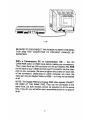
Radio and Television Interference
This monitor generates and uses radio frequency energy. If not
. properly installed and used in strict accordance with the manufac-
turer's instructions, this equipment may interfere with radio and
television reception. This machine has been tested and found to
comply with the limits for a Class B computing device
in
accor-
dance with specifications
in
Part 15, Subpart J of FCC rules, which
are designed to provide reasonable protection against such inter-
ference in a residential installation. If you suspect interference, test
this equipment by turning it off and on. If you determine that there is
interference with radio or television reception, try one or more of
the following measures to correct it:
• Reorient the receiving antenna.
• Move the computer and the monitor away from the receiver
that is picking up the interference.
• Change the relative positions of the computer and the
receiver.
• Plug the computer into a different outlet so that the computer
and the receiver are on different branch circuits.
CAUTION: Only peripherals with shield-grounded cables (comput-
er
input-output devices, terminals, printers, etc.), certified to comply
with Class B limits, can be attached to this monitor. Operation with
non-certified peripherals is likely to result
in
communications
interference.
Your house AC wall receptacle must be a three-pronged type (AC
ground). If not, contact an electrician to install the proper recepta-
cle. If a multi-connector box is used to connect the computer and
peripherals to AC, the ground must be common to all units.
If necessary, consult your dealer or an experienced radio/television
technician for additional suggestions.
You
may also consult the
following booklet prepared by the Federal Communications Com-
mission: How to Identify and Resolve Radio - TV Interference
Problems, available from the U.S. Government Printing Office,
Washington, DC, 20402, Stock #004-000-0035-4.


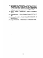
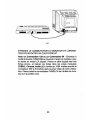
Introducing
Your
Monitor
The Commodore 1084S is a full-color,
13
inch monitor for use with
the Commodore 64, Commodore 128, Commodore
PC
and the
Amiga family of computers. The monitor provides audio output
in
stereo for use with computer systems with stereo capabilities (like
the Amiga computers). Your 1084Soperates on the North Ameri-
can Television Standard (NTSC}
wB1Ch
is used throughout the
United States and Canada. This
-manual
explains how to connect
the 1 084S monitor to your computer and how.to.tlse the various
operating modes and picture controls.
The 1084S works
in
four different operating modes: Composite
(NTSC. standard), Separated LCA (Luma-Chroma-Audio), Digital
RGBI (Red/Green/Blue Intensity), and Analog
RGB.
It also allows
both a 40-column screen display, for use
in
Composite
and
-Sepa-
rated modes, and
an
80-column display for Digital and Analog
RGB
output. The mode you choose will depend
on
the type of computer
you are using
..
Before you proceed any further, check to make sure you have
received everything:
• One 1084S monitor
• Four cables:
• For connecting
an
Amiga computer - one cable with a 23-
pin D (rectangular) connector
on
the computer end and a 6-
pin DIN (round) connector
on
the monitor end (provides
an
Analog RGB display)
• For connecting a Commodore
PC
or Commodore 128 -
one cable with a 9-pin D connector
on
the computer end
and
an
8-pin DIN connector
on
the monitor end (provides
an
RGBldisplay)
• For connecting a Commodore 128 or Commodore 64 -
one cable with
an
8-pin
DIN
connector
on
the computer
end and 3 phono plugs
on
the monitor end (provides a
Separated LCA display)
• For connecting
an
Amiga computer's audio capabilities -
one cable with two RCA phono plugs
on
each end
• Two warranty cards
1

The cables included with your 10848 monitor are
RF
shielded
cables. Be sure to use only RF shielded cables when connecting
this monitor to a computer.
The chart below indicates the operating mode(s) suitable to the
type of computer you are using:
Recommended
Operating
Mode
by
Computer
Model
40-column display 80-column display
Composite Separated
LCA
Digital
RGBI
Analog
RGB
Amiga computers
Commodore
PC
10/20
Commodore 128
Commodore 64
X
X
X
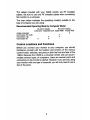
Control Locations and Functions
X
X
X
Before you connect your monitor to your computer, you should
familiarize yourself with the location and function of the various
control knobs, switches, and ports
on
both the front and rear of the
10848. Because the 10848
is
a universal monitor and can accom-
modate several types of computers, there are several ports and
connectors
on
the monitor's cabinet. However, if you are only using
your monitor with one type of computer, you will only need to use a
few of the ports.
2

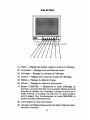
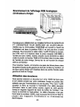
Front
View
.j.-~--9
2 3 4 5
6 7 8
(1) Hue - Adjusts the red and green tints in the display.
(2) Brightness - Adjusts the brightness of the screen.
(3) Contrast - Adjusts the display's contrast.
(4)
Color - Adjusts the color levels
in
the display.
(5) Sharpness - Adjusts the picture's detail.
(6)
Volume - Adjusts the speaker's loudness.
(7) CVBS/RGB Button - Selects the display mode of the monitor.
The button should be set to the relevant position before con-
necting the monitor to your computer. When the button is
pushed halfway in, the monitor is set to Composite/Separated
LCA mode. To use in RGB/RGBI mode, 'the button should be
left fully extended.
(8)
Power Switch
(9) A convenient tilt base folds
out
of the bottom allowing you to
adjust the monitor's viewing angle.
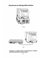
3

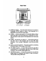
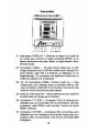
Rear View
1 2 3 4 5 6 7 8 9 101112
(1) CVBS/LCA Switch - Push the button half-way in to receive a
Composite (NTSC) signal
or
leave it fully extended for a
Separated Luma-Chroma-Audio signal.
(2) CVBS/L - A phono jack
used,
for a Composite
d~play
with
an
older C64 (with a 5-pin DIN video port), a television or a VCR.
This connector is also used for the Separated LCA mode (see
below).
(2) CVBS/L, (3) Chroma, (4) Audio (L) - Three phono jacks for
use with a
64.
or
128-
computer
with-
an
8-pin DIN video
connector. This provides Separated Luma-Chroma-Audio
inplJt.
(4)
Audio (L) and (5) Audio (R)
-Two
phono jacks for connecting
the audio output of the Amiga
to
the monitor.
·(6)
TtL
RGB Connector - An 8-pin DIN connector for use with a
Commodore
PC
or Commodore 128 with a 9-pin RGBI video
connector. This provides Digital RGBI input.
(7)
L1N.RGB
Connector - A 6-pin DIN connector for use with the
Arniga family of computers with 23-pin D video connectors.
This provides Analog RGB input.
4

(8) VCR
switch·-
This button allows you to adjust
your
monitor's
circuitry so that you can· use' it as a display for your VCR or .
Video Camera. Push
this button half-way in when using your
monitor with a VCR
or
video camera.
(9) V-Height - Adjusts the image height on the screen.
(10) Vert. Centering - Centers the image' vertically, from top to
bottom.
(11)
Horiz. Centering - Centers
the
image horizontally, from left to
. right. .
(12) H. Width - Adjusts the image width on the screen.
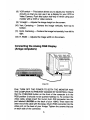
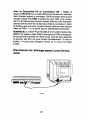
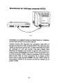
Connecting the. AnalogRGB Display
. (Amiga computers) '."
Amiga500
First, TURN OFF THE POWER TO BOTH THE.MONlTOR AND
THE COMPUTER TO PREVENT DAMAGE BY SHORTING. Cbeck .
that the CVBS/RGB button on the froht
of
the computer is in the
RGB position (it should 'not be pushed halfway in).
To
connect the
video cable, simply insert the round, 6-pin DIN connector inio the
.port labeled"
LlN~RG8
on the back
of
your 1 084S
..
Then insert the
other end of
~he
cable with the large, 23-pin RGB connector
ihtothe
video port on the back
of
YoufAmiga. Tighten the screws
that
are
on each side
of
the connector. ' ..
. 5

To
connect the audio, one pair of phono plugs are plugged into the
left and right audio jacks on the back of your monitor, and the other
pair of plugs are inserted into the Amiga's left and right audio ports.
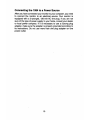
Usi(lg Headphones
You
can connect headphones to your 10848 so that the stereo
sounds generated
by
your Amiga computer can only be heard
through the headset.
To
do this, simply insert the plug on the end of
a standard headphone cable into the small, silver port on the left
side (as you face the front) of the monitor's cabinet. It is
in
the
vicinity of the speaker. A headphone cable is not included with your
monitor but should be readily available at most computer and
electronics stores.
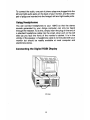
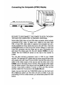
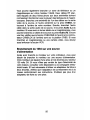
Connecting the Digital RGBI Display
PC
Colt
6

C 128
BE SURE TO DISCONNECT THE POWER
TO
BOTH THE MONI-
TOR
AND
THE
COMPUTER
TO
PREVENT
DAMAGE BY
SHORTING.
With a Commodore
PC
or Commodore 128 - Set
the
CVBS/RGB button to
RGB
mode before making any connections.
Then, insert the 8-pin DIN connector into the port labeled
TTL
RGB
• on the back of your 1084S and the 9-pin D connector into the video
port on your computer. (Be sure to tighten the screws
on
each side
of the connector.) Depending
on
which computer you have, the
video port may be labeled Video or
RGBI-
or it may not be
label~d
at all.
NOTE: The Digital
RGBI
and Analog
RGB
video signals CANNOT
BE USED AT THE SAME TIME. They can be connected at the
same time, but both devices cannot be powered
on
at the
same--
time. If you do, you will either see a scrambled picture or
no
picture
at all.
7

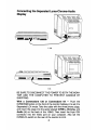
Connecting the Separated Luma-Chroma-Audio
Dispiay
•
IJ
0
1Iii!I_
C 128
IJI@
C 64
BE
SURE
TO
DISCONNECT THE POWER
TO
BOTH
THE MONI-
TOR
ANt)
THE COMPUTER TO PREVENT DAMAGE BY
SHORTING.
With
a
Commodore
128
or
Commodore
64 - Push the
CVBS/RGB button
on
the front of the monitor halfway
in
to set
it
to
Separated
LCA
mode. Take the cable with the three phono plugs,
and insert the plugs into the jacks labeled CVBS/L, Chroma,
and.
Audio
(L)
on
the back of the 1084S. Then insert the 8-pin
DIN
connector into the Video port
on
your computer. Also set the
CVBS/LCA switch
on
the rear of the monitor to
LCA.
8

/'
Connecting the Composite (NTSC) Display
CII@
C64
BE SURE TO DISCONNECT THE POWER
TO
BOTH THE MONI-
TOR AND THE COMPUTER TO PREVENT SHORTING.
Some older C64's have a 5-pin
DIN
video connector which outputs
composite NTSC video.
To
attach your 10845 to this older style
C64, a 5-pin DIN video cable is required (not included, but com-
monly available at many stores that carry the C64
line)-.
Push the
eVBS/RGB button on the front of the monitor halfway
in.
Insert the
5-pin DIN connector into the Video port on your Commodore 64,
and insert the phono jack into the port labeled CVBS/L on your
1084S. Set the CVBS/LCA switch on the rear of the monitor to
CVBS.
You can also connect a television tuner or
VCR
to your 1084S
monitor. Two standard RF cables with two phono plugs at both ends
will usually work with most TVs and VCRs. Connect one end of one
cable to the video output of the source and the other end to the
CVBS/L port on the back of your monitor. Then plug the other cable
into the audio output of the source and the
Audio
(L) jack on the
monitor. If you have a stereo TV tuner or VCR, you may connect
another cable from the source to the
Audio
(R) jack.
Again, be sure that both the CVBS/RGB button (on the front) and
the CVBS/LCA switch (on the rear) are set to CVBS. If you are
connecting a VCR or video camera, you should also press the VCR
button.
9

Connecting
the
1084
to
a
Power
Source
After you have connected your monitor to your computer, you need
to connect the monitor to
an
electrical source. Your monitor is
equipped with a 3-pronged, 120-volt
AC
line plug. If you are not
sure of the type of power supply to your home, consult your dealer
or local power company. If it is necessary to use a 2-prong plug
adapter, make sure the adapter
is
properly grounded according to
its instructions.
Do
not use more than one plug adapter
on
one
power outlet.
10

Safety Precautions
This monitor has been engineered and manufactured to assure
your personal safety. However, improper use can result
in
potential
electrical shock or fire hazards. Please observe the following basic
rules when using your monitor. Also, heed all warnings and instruc-
tions marked on the monitor's cabinet.
DO NOT ATTEMPT TO SERVICE THE MONITOR YOURSELF.
OPENING OR REMOVING COVERS MAY EXPOSE YOU TO
DANGEROUS VOLTAGES OR OTHER HAZARDS. DANGEROUS
HIGH VOLTAGE
IS
PRESENT EVEN WHEN THE ·'MONITOR
IS
UNPLUGGED.
REFER
ALL
SERVICING
TO
QUALIFIED
PERSONNEL.
Do Not overload AC outlets or extension cords. This may result
in
a
shock or fire hazard.
Do Not use more than one plug adapter in one power outlet.
Do Not use the monitor near water or excessive moisture.
Do Not block the monitor's ventilation slots by placing objects on
top or underneath the monitor.
Do Not place the monitor
• in a "built-in" enclosure unless proper ventilation
is
provided
• near or over a radiator or heat register
• where. sunlight or bright room light will fall directly on the
screen
• on a sloping shelf or try to mount it on a wall.
Do Not use alcohol, ammonia based products, or an aerosol spray
to clean the monitor screen.
To
clean the screen, unplug the moni-
tor, and wipe with a slightly damp cloth.
Do Not bring magnetic devices near the screen. They may damage
the color purity of the picture.
Unplug the Monitor
• if you will not be using it for an extended period
• during an electriGal storm
• before cleaning it.
11

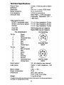
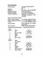
Technical
Specifications
Picture
Tube:
Deflection:
Resolution:
Raster frequency:
Line frequency:
Character field:
Video signal (by port):
NTSC/L (composite video)
NTSC/L (luminance signal)
Chroma
6-pin
DIN
8-pin
DIN
PIN
ASSIGNMENT
Pin
No.
1
2
3
4
'5
6
Pin
No.
1
2
3
4
5
6
7
8
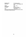
Sound output:
Audio signal
Mains voltage:
Signal
Green
Horizontal Sync
Ground'
Red
Blue
Vertical Sync
Signal
Not
connected
Red
Green
Blue
Intensity
Ground
Horizontal Sync
Vertical Sync
Power consumption:
Dimensions:
Weight:
13
inch,
in-line dot, pitch 0.42mm
90°
640
lines
in
center
(RGB
mode)
60
Hz
(autoswitch)
15734
Hz
(autoswitch)
RGB,
RGBI
- 2,000 characters
Composite, Separated
LCA
-
1
,eoo
chars.
1 V
±
0.5
Vpp;
Impedance-75
ohm
1 V ±
0.1
Vpp;
Impedance-
75
ohm
1 V ±
0.1
Vpp;
Impedance-75
ohm
RGB
Analog
(see
pin
diagram)
Digital
RGBI
(see
pin
diagram)
PIN
DIAGRAM
ANALOG
RGB
INPUT
DIGITAL
RGBI
INPUT
1 W -
5%
distortion (per channel)
150mV
- 2
Veff;
Impedance - 10K
ohm
120V
±
10%
75W
320
x
350
x
387mm
12.6
x
13.8
x
15.2
inches
11
kg
(24.25
Ibs)
In
support
of
our policy
of
continuous
product
improvement,
the
above
specifications
are
subject
to
change
without
notice,
12

COMMODORE
1084S
'MONITEUR
COULEUR
AVEC
SORTIE
EN
STEREO
13

Interference
radio
et
television
Ce
moniteur produit et utilise de I'energie a frequence radio. S'iI
n'est pas installe correctement
ou
utilise dans
Ie
strict respect des
instructions du fabricant, cet equipement peut gener la reception
radio et television. Cette machine a ete testee et declaree con-
forme aux limites d'un appareil de calcul de classe
B,
conforme-.
ment aux specifications de la partie 15, sous-partie
J des regles de
la FCC, qui ont ete congues pour garantir une protection raisonna-
ble contre les interferences dans les installations residentielles.
Si
vous soupgonnez qu'il y a interference, testez cet equipement en
Ie
mettant successivement sous tension et hors tension.
Si
vous
etablissez qu'iI y a interference avec la reception radio
ou
televi-
sion, essayez une ou plusieurs des mesures suivantes pour cor-
riger la situation:
• Reorientez I'antenne de reception.
• Eloignez I'ordinateur et
Ie
moniteur
du
recepteur qui est affecte
par I'interference.
• Changez les positions relatives de I'ordinateur et du recepteur.
• Branchez I'ordinateur sur une prise.differente, afin que I'ordin-
ateur et
Ie
recepteur soient sur des circuits differents.
ATTENTION: Vous ne pouvez brancher sur ce moniteur que des
peripMriques equipes de cables blindes et mis
a la masse (dispo-
sitifs d'entree et sortie d'ordinateurs, terminaux, imprimantes, etc.),
certifies conformes aux limites de la Classe
B.
Le
fonctionnement
de peripheriques non certifies risque de produire des interferences
de communication.
La prise CA de votre maison do
it
etre
du
type a trois broches (CA
mis
a la masse).
Si
ce n'est pas
Ie
cas, contactez
un
electricien
pour installer la prise necessaire.
Si
vous utilisez une
b~Tte
a
connexions multiples pour brancher I'ordinateur et les peripheri-
ques sur
Ie
secteur, la mise a la masse doit etre commune a tous
les appareils.
Si
necessaire, consultez votre depositaire
ou
un
technicien experi-
mente de radio/television pour obtenir d'autres suggestions. Vous
pouvez egalement consulter
Ie
livret suivant, prepare par la "Fed-
eral Communications Commission": "How to Identify and Resolve
Radio - TV Interference Problems", produit par
Ie
"US
Govern-
ment Printing Office", Washington,
DC,
20402, no de stock 004-
000-0035-4.
14
La page est en cours de chargement...
La page est en cours de chargement...
La page est en cours de chargement...
La page est en cours de chargement...
La page est en cours de chargement...
La page est en cours de chargement...
La page est en cours de chargement...
La page est en cours de chargement...
La page est en cours de chargement...
La page est en cours de chargement...
La page est en cours de chargement...
La page est en cours de chargement...
La page est en cours de chargement...
La page est en cours de chargement...
La page est en cours de chargement...
La page est en cours de chargement...
-
 1
1
-
 2
2
-
 3
3
-
 4
4
-
 5
5
-
 6
6
-
 7
7
-
 8
8
-
 9
9
-
 10
10
-
 11
11
-
 12
12
-
 13
13
-
 14
14
-
 15
15
-
 16
16
-
 17
17
-
 18
18
-
 19
19
-
 20
20
-
 21
21
-
 22
22
-
 23
23
-
 24
24
-
 25
25
-
 26
26
-
 27
27
-
 28
28
-
 29
29
-
 30
30
-
 31
31
-
 32
32
-
 33
33
-
 34
34
-
 35
35
-
 36
36


dans d''autres langues
- English: Commodore 1084S User manual
Documents connexes
-
Commodore 1084S Manuel utilisateur
-
-
-
-
-
-
-
-
