

COMMODORE 2002
COLOR/RGB
MONITOR
USER'S GUIDE

USER'S GUIDE STATEMENT
This equipment generates and uses radio frequency energy. If it is
not properly installed and used in strict accordance with the manu-
facturer's instructions, this equipment may interfere with radio and
television reception. This machine has been tested and found to
comply with the limits for a Class B computing device in accordance
with the specifications in Subpart J of Part 15 of FCC Rules, which
are designed to provide reasonable protection against such interfer-
ence in a residential installation. If you suspect interference, you can
test this equipment by turning it off and on. If you determine that
there is interference with radio or television reception, try one or
more of the following measures to correct it:
• reorient the receiving antenna.
• move the computer and this monitor away from the receiver that is
picking up interference.
• change the relative positions of the computer equipment and the
receiver.
• plug the computer and this monitor into a different outlet so that
the computer and the receiver are on different branch circuits.
If necessary, consult your Commodore dealer or an experienced
radio/television technician for additional suggestions. You may also
wish to consult the following booklet, which was prepared by the
Federal Communications Commission: How to Identify and Resolve
Radio-TV Interference Problems. This booklet is available from the
U.S. Government Printing Office, Washington, D.C., 20402, Stock
No. 004-000-00345-4.
in

WARNING
THERE IS DANGEROUS HIGH VOLTAGE PRESENT IN THIS
MONITOR. DO NOT EXPOSE THIS EQUIPMENT TO MOISTURE.
SUCH EXPOSURE COULD CAUSE FIRE OR ELECTRIC SHOCK.
If you have technical problems with your Commodore 2002 monitor,
unplug the set and call your dealer or service technician.
Copyright © 1986 by Commodore Electronics Limited
All rights reserved
Commodore 2002
T
" is a trademark of Commodore Electronics Limited
Commodore 64® is a registered trademark of Commodore Electronics
Limited
Commodore Plus/4™ is a trademark of Commodore Electronics Limited
Commodore 16™ is a trademark of Commodore Electronics Limited
Commodore 128™ is a trademark of Commodore Electronics Limited
Commodore Amiga® is a trademark of Commodore-Amiga, Inc.
Commodore PC™ is a trademark of Commodore Electronics Limited
IV

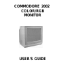
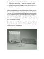
INTRODUCING YOUR MONITOR
The Commodore 2002 monitor has a 13-inch diagonal screen and is
capable of four different operating modes: composite (NTSC stan-
dard); separated luma and chroma; digital RGBI (Red/Green/Blue
Intensity); and analog RGB. The different modes are used for the
displays of different computers, as shown in the chart below. The
2002 has both 40- and 80-column display capability: composite and
separated modes use 40-column screens; digital RGBI and analog
RGB displays are 80 columns. With the flick of a switch, you can use
the 2002 as a 40-column composite color monitor or an 80-column
RGBI monitor or an analog RGB monitor. The 2002 can be used with
the Commodore 64, 128, Plus/4, 16, PC and Commodore Amiga
computers.
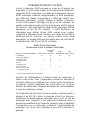
Recommended Operating Mode by Computer Model
SEPARATED
OPERATING MODE: COMPOSITE LUMA/CHROMA DIGITAL RGB) ANALOG RGB
COLUMNS: 40 40 80 80
Commodore AMIGA X
Commodore 128 X X
Commodore 64 X X
PLUS/4 X
Commodore 16 X
Commodore PC X
TV tuner or VCR X
X—Recommended operating mode
Please read this brief manual carefully before you use your monitor.
The manual shows you how to connect the monitor and use the
operating modes correctly. It also explains how to use the picture
control knobs, which are like the control knobs on a color TV.
Be sure to take note of the warnings in this manual, and do NOT
remove the back cover or otherwise attempt to service this monitor
for safety reasons. If you have problems with your monitor that are
not covered in this manual, see your Commodore dealer or a quali-
fied technician. Attempting to service this monitor yourself voids your
warranty.

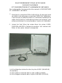
CONNECTING YOUR MONITOR TO A COMPUTER
The monitor connection cable connects your monitor to a Commo-
dore personal computer. The cable or cables you'll hook up depends
on the computer model you have.
There are either one or two different cables included with the 2002
monitor to connect it to your computer, depending on which cable
option you purchased.
Shielded cable must be used for the connection between this moni-
tor and your computer.
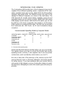
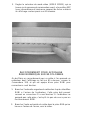
The C-128 Cable Option includes two cables:
• One cable is an eight-pin DIN cable designed for connecting a
separate chroma/luma display. "Eight-pin" refers to the number of
metal "pins" on the inside of the large round end of the cable. This
cable also has three different colored plugs on the other end.
These plugs are color-coded for the correct jacks they plug into on
the back of the monitor.
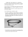
• The other cable is a nine-pin cable, with two rectangular ends (D-
connectors) with nine pins inside that connect to the RGBI socket
on the back of the computer and the monitor.

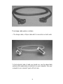
The Amiga cable option contains:
• The Amiga cable, a 23-pin cable with D-connectors on both ends.
To find out which kind of cable you should use, see the above table
and look at the audio/video connector(s) on your computer. See your
computer's user manual if you're still not sure.
3

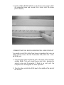
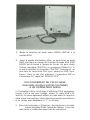
CONNECTING THE 40-COLUMN SEPARATED
CHROMA/LUMA DISPLAY
To connect the monitor for SEPARATED CHROMA/LUMA oper-
ation:
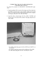
1. Plug the eight-pin DIN connector (the larger end of the cable) into
the VIDEO connector port on your computer. Make sure the small
dent on the metal end of the cable that you plug into the computer
is facing up, and push in the cable end firmly.
2. Insert the three colored plugs into the LUMA, CHROMA and
AUDIO jacks on the back of the monitor. The plugs and jacks are
color-coded:
• the white output plug goes into the AUDIO jack (WHITE) on
the monitor.
• the yellow output plug goes into the LUMA jack (YELLOW).
• the red output plug goes into the CHROMA jack (RED).
4

3. Set the VIDEO MODE SWITCH on the front control panel to SEP
(for separated luma and chroma) for a sharp color 40-column
picture display.
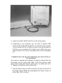
CONNECTING THE 80-COLUMN DIGITAL RGBI DISPLAY
You would connect this cable if you have a computer which uses an
eighty-column screen, like the Commodore 128, which has a nine-
pin RGBI port.
1. Plug the silver cable end into the port on the back of the computer
marked RGBI. That port should have a jack that is designed to
accept a nine pin D-connector. If there is no such port, the
computer was not designed for RGBI operation.
2. Plug the other end into the RGB input in the middle of the back of
the monitor.

3. Switch the VIDEO MODE SWITCH to the RGB position.
4. Depending on your computer, you can select a specific RGBI
mode with the RGB MODE SWITCH on the back of the monitor.
You can select DIGITAL or ANALOG input. If you set the switch to
DIGITAL, you can choose POS (high sync) or NEG (low sync).
Select DIGITAL POS for the Commodore 128 or the Commodore
PC.
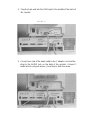
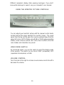
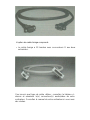
CONNECTING THE 80-COLUMN ANALOG RGB DISPLAY
TO AN AMIGA
If you have a computer which displays its output in analog RGB, like
the Amiga, use the 23-pin RGB cable. You'll also need an audio
cable (a thin cable with identical phono jacks on either end) and a
"Y" adapter cord (which you'll need to buy).
1. Plug the larger 23-pin end of the cable into the port on the back of
the Amiga marked RGB. Manually tighten the thumb screws on
either side of the connector.

2. Plug the 9-pin end into the RGB input in the middle of the back of
the monitor.
t-
^&
|
^
14
-f-
.^
i .•
3. Connect one end of the audio cable to the Y adapter cord and the
other to the AUDIO jack on the back of the monitor. It doesn't
matter which end goes where, since they're both the same.

4. Brancher les fiches de I'adaptateur en Y dans les prises gau-
che et droite du haut-parleur, a I'arriere de I'ordinateur Amiga.
5. Mettre Ie selecteur de mode video (VIDEO MODE SWITCH) a
la position RGB.
6. Selectionnez la position "Analog" sur Ie commutateur "RGB
mode".
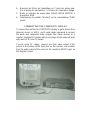
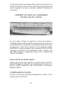
CONNECTING THE COMPOSITE DISPLAY
To connect the monitor for COMPOSITE display to get a picture from
television tuners or VCR's, you'll need cables designed to connect
the audio and composite video outputs from these devices to a
monitor. Standard RF cables with phono plugs at both ends will work
with most VCR's and TV tuners.
If you're using RF cables, connect one from video output of the
source to the yellow LUMA input jack on the monitor, and another
from the audio output of the source to the monitor's AUDIO input, as
this diagram shows.

Set the VIDEO MODE SWITCH to COMP (for composite) to view
computer or video output in a 40-column color picture display.
TURNING ON YOUR MONITOR
After connecting your monitor to the computer and inserting the
three-pronged electrical plug into a power outlet, you are ready to
turn on your monitor. Follow these simple steps:
1. Turn the monitor on by pushing down the power switch. The
POWER INDICATOR LIGHT on the front of the monitor shows
, you when the power is on. Always turn the monitor on BEFORE
you turn the computer on.
Later, when you're ready to turn the power off, press the power
button again. The power light will go out.
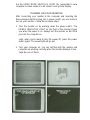
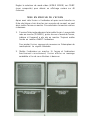
2. Turn your computer on. You can tell that both the monitor and
computer are working correctly when the monitor displays a mes-
sage like one of these:

Different computers display other opening messages. If you don't
know what message to expect, see your computer's user manual.
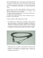
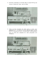
USING THE MONITOR PICTURE CONTROLS
You can adjust your monitor's picture with the manual control knobs
located behind the panel beneath the monitor screen. The panel
opens from the top; just flip open the cover by pulling it down from the
upper left corner. NOTE: When using RGBI or RGB analog operating
modes, some of these controls (tint, color) have no effect, since the
color shades and intensities are preset.
VIDEO MODE SWITCH
As mentioned earlier, you use this switch to select the display mode
of the monitor. The switch can be set at COMP (composite), SEP
(separated chroma/luma) or RGB.
VOLUME CONTROL
Turn this knob to the right to increase sound volume and to the left to
decrease the volume.
10

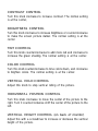
CONTRAST CONTROL
Turn this knob clockwise to increase contrast. The normal setting
is at the center,
BRIGHTNESS CONTROL
Turn this knob clockwise to increase brightness or counterclockwise
to make the screen picture darker. The normal setting is at the
center.
TINT CONTROL
Turn this knob counterclockwise to add more red and clockwise to
increase the green shading. The normal setting is at the center.
COLOR CONTROL
Turn this knob counterclockwise to tone colors down, and clockwise
to brighten colors. The normal setting is at the center.
VERTICAL HOLD CONTROL
Adjust this knob to stop vertical rolling of the picture.
HORIZONTAL POSITION CONTROL
Turn this knob clockwise to move the center of the picture to the
right. Turn it counterclockwise shift the center of the picture to the
left.
VERTICAL HEIGHT CONTROL (on back of monitor)
Adjust this with a screwdriver to increase or decrease the vertical
height of the picture.

SAFETY
PRECAUTIONS
This unit has been engineered and manufactured to assure your
personal safety. But improper use can result in potential electri-
cal shock or fire hazards. In order not to defeat the safeguards
incorporated in this monitor, observe the following basic rules for its
installation, use and servicing. Follow all warnings and instructions
marked on your video monitor.
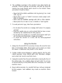
Installing the Monitor
1. Your set is equipped with a three-pronged 120-volt AC line plug.
This safety feature allows the plug to fit into the power outlet
only one way. If it is necessary to use a 2-prong plug adapter,
make sure the adapter is properly grounded according to its
instructions.
2. Operate the set only from a power source as indicated on the set
or refer to the user's manual for this information. If you are not
sure of the type of power supply to your home, consult your dealer
or local power company.
3. Overloaded AC outlets and extension cords are dangerous. So
are frayed power cords and broken plugs. They may result in a
shock or fire hazard. Replace worn or damaged cords and plugs.
Do not use more than one plug adapter on one power outlet.
4. Do not allow anything to rest on or roll over the power cord, and
do not place the set where the power cord is subject to traffic or
abuse. This may result in a shock or fire hazard.
5. Do not use this monitor near water—for example, near a bathtub,
washbowl, kitchen sink, laundry tub, in a wet basement, or near a
swimming pool, etc.
12

6. The ventilation openings in the monitor's case allow heat to be
released. If these openings are blocked, heat built up inside the
monitor may cause failures which result in a fire hazard. These
precautions should be taken:
• Never block the bottom ventilation slots by placing it on a bed,
sofa, rug, etc.
• Never place a set in a "built-in" enclosure unless proper venti-
lation is provided.
• Never cover the ventilation openings with cloth or other material.
• Never place the set near or over a radiator or heat register.
7. To avoid personal injury, take these precautions:
• Do not place the monitor on a sloping shelf unless it is properly
secured.
• Place the monitor only on a cart or stand that has been recom-
mended by the manufacturer for that purpose.
• Do not place the monitor on a cart with small casters and try to
roll it across door thresholds or deep-pile carpets.
• To mount the monitor on a shelf, use the factory-approved
instructions.
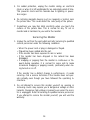
Using the Monitor
1. Always turn the set off if it is necessary to leave the room for more
than a short period of time. Never leave a set on when you leave
the house. A malfunction may result in a fire hazard.
2. Caution children about dropping or pushing objects into the set's
cabinet openings. Some internal parts carry hazardous voltages
and contact can result in electrical shock.
3. Unplug the monitor from the wall outlet before cleaning the face of
the picture tube. Use a slightly damp (not wet) cloth. Do not use
an aerosol directly on the picture tube since overspray can cause
electrical shock.
4. Never add accessories to a monitor that have not been designed
tor this purpose. Such additions may create an electrical shock
hazard.
13

5. For added protection, unplug the monitor during an electrical
storm or when it is left unattended for an extended period of time.
This prevents shock and fire hazards due to lightning or power-
line surges.
6. Do not bring magnetic devices such as magnets or motors near
the picture tube. This could distort the color purity of the picture.
7. Sometimes you may feel static electricity when you touch the
surface of the picture tube. This is normal for any TV set or
monitor and is harmless to you and to the monitor.
Servicing the Monitor
1. Unplug the set from the wall outlet and refer servicing to qualified
service personnel under the following conditions:
• When the power cord or plug is damaged or frayed.
• If liquid has been spilled into the set.
• If the monitor has been exposed to rain or water.
• If the monitor has been dropped or the cabinet has been
damaged.
• If snapping or popping from the monitor is continuous or fre-
quent during operation. It is normal for some sets to make
occasional snapping or popping sounds, particularly when be-
ing turned on or off.
If the monitor has a distinct change in performance, it needs
servicing. Call a service technician if the monitor does not oper-
ate normally even though you have followed the operating in-
structions.
2. Do not attempt to service this monitor yourself, as opening or
removing covers may expose you to dangerous voltage or other
hazards. Dangerous high voltage is present even when the moni-
tor is unplugged. Refer all servicing to qualified service personnel.
If you attempt to service the monitor yourself, you will void the
warranty.
14

3. When replacement parts are required, have the service techni-
cian verify in writing that the replacements he used have the
same safety characteristics as the original parts. Use of manufac-
turer's specified replacements can prevent fire, shock or other
hazards.
4. Upon completion of any service or repairs to the set, please ask
the service technician to perform the safety check described in
the manufacturer's service literature.
5. When a video monitor reaches the end of its useful life, improper
disposal could result in a picture tube implosion. Ask a qualified
service technician to dispose of the set.
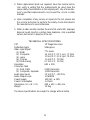
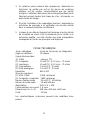
TECHNICAL SPECIFICATIONS
CRT
Deflection Angle
Video Input Signal
(1) RGBI
(2) Composite
(3) Luma
(4) Chroma
(5) RGB Analog
Resolution
Character Field
(1) RGB, RGBI
(2) Composite, Separate
Audio Input Level
Audio Output Level
Power Supply
Power Consumption
Dimensions (H x W x D)
Weight
13" Diagonal screen
90 degrees
TTL levels
1.0 Volt P-P, 0.3 V sync, 75 Ohm
1.0 Volt P-P, 0.3 V sync, 75 Ohm
1.0 Volt P-P, 75 Ohm
0.7 Volt P-P, 75 Ohm
640
x
200
2,000 characters
1,000 characters
1.0 Volt P-P, -lOKOhm
1.0WRMS
120
VAC
±
10%
1 A Norn
438
x
439
x 465 mm
13.5kg
The above specifications are subject to change without notice.
15

COMMODORE 2002
MONITEURCOULEUR
MANUEL D'UTILISATION
La page est en cours de chargement...
La page est en cours de chargement...
La page est en cours de chargement...
La page est en cours de chargement...
La page est en cours de chargement...
La page est en cours de chargement...
La page est en cours de chargement...
La page est en cours de chargement...
La page est en cours de chargement...
La page est en cours de chargement...
La page est en cours de chargement...
La page est en cours de chargement...
La page est en cours de chargement...
La page est en cours de chargement...
La page est en cours de chargement...
La page est en cours de chargement...
La page est en cours de chargement...
La page est en cours de chargement...
-
 1
1
-
 2
2
-
 3
3
-
 4
4
-
 5
5
-
 6
6
-
 7
7
-
 8
8
-
 9
9
-
 10
10
-
 11
11
-
 12
12
-
 13
13
-
 14
14
-
 15
15
-
 16
16
-
 17
17
-
 18
18
-
 19
19
-
 20
20
-
 21
21
-
 22
22
-
 23
23
-
 24
24
-
 25
25
-
 26
26
-
 27
27
-
 28
28
-
 29
29
-
 30
30
-
 31
31
-
 32
32
-
 33
33
-
 34
34
-
 35
35
-
 36
36
-
 37
37
-
 38
38


dans d''autres langues
- English: Commodore 2002 User manual
Documents connexes
-
Commodore 1084S Manuel utilisateur
-
-
-
-
-
-
-
-