Cub Cadet XT1 Enduro Manuel utilisateur
- Catégorie
- Souffleuses à neige
- Taper
- Manuel utilisateur
Ce manuel convient également à

Printed In USA
OperatOr’s Manual
Safe Operation Practices • Set-Up • Operation • Maintenance • Service • Troubleshooting • Warranty
WARNING
READ AND FOLLOW ALL SAFETY RULES AND INSTRUCTIONS IN THIS MANUAL
BEFORE ATTEMPTING TO OPERATE THIS MACHINE.
FAILURE TO COMPLY WITH THESE INSTRUCTIONS MAY RESULT IN PERSONAL INJURY.
P. O. Box 1386, 97 KENT AVENUE, KITCHENER, ON N2G 4J1
XT1 and XT2 Enduro Series™ Tractor
769-11062
11. 24.15

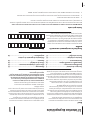
Safe Operation Practices ........................................ 3
Assembly & Set-Up .................................................. 9
Controls & Features ................................................14
Operation ................................................................ 17
Maintenance & Adjustment .................................21
Service .................................................................... 26
Troubleshooting .................................................... 30
Attachments & Accessories ...................................31
Replacement Parts ............................................... 32
Emission control warranty statement ................. 34
Warranty ............................................................... 36
Customer Support
Please do
NOT
return the unit to the retailer from which it was purchased, without first contacting Customer Support.
If you have difficulty assembling this product or have any questions regarding the controls, operation, or maintenance of
this machine, you can seek help from the experts. Choose from the options below:
◊ Visit our web at www.cubcadet.ca
◊ Locate your nearest dealer from Customer Support: 1-800-668-1238
◊ Contact Cub Cadet • P.O. Box 1386 • 97 Kent Avenue • Kitchener, Ontario, Canada • N2G 4J1
To The Owner
1
2
Table of Contents
Thank you for purchasing your new equipment. It was carefully
engineered to provide excellent performance when properly
operated and maintained.
Please read this entire manual prior to operating the equipment.
It instructs you how to safely and easily set up, operate and
maintain your machine. Please be sure that you, and any other
persons who will operate the machine, carefully follow the
recommended safety practices at all times. Failure to do so could
result in personal injury or property damage.
All information in this manual is relative to the most recent
product information available at the time of printing. Review
this manual frequently to familiarize yourself with the machine,
its features and operation. Please be aware that this Operator’s
Manual may cover a range of product specifications for
various models. Characteristics and features discussed and/or
illustrated in this manual may not be applicable to all models.
The manufacturer reserves the right to change product
specifications, designs and equipment without notice and
without incurring obligation.
If you have any problems or questions concerning the machine,
phone your local service dealer or contact us directly. Customer
Support telephone numbers, website address and mailing
address can be found on this page. We want to ensure your
complete satisfaction at all times.
Throughout this manual, all references to right and left side of the
machine are observed from the operating position.
The engine manufacturer is responsible for all engine-related
issues with regards to performance, power-rating, specifications,
warranty and service. Please refer to the engine manufacturer’s
Owner’s/Operator’s Manual, packed separately with your
machine, for more information.
Thank You
Record Product Information
Before setting up and operating your new equipment, please
locate the model plate on the equipment and record the
information in the provided area to the right. You can locate the
model plate under the operator’s seat. Flip the seat forward to
view the model plate. This information will be necessary, should
you seek technical support via our web site or with your local
dealer.
Model NuMber
Serial NuMber

Important Safe Operation Practices
2
3
General Operation
1. Read, understand, and follow all instructions on the
machine and in the manual(s) before attempting to
assemble and operate. Keep this manual in a safe place for
future and regular reference and for ordering replacement
parts.
2. Be familiar with all controls and their proper operation.
Know how to stop the machine and disengage them
quickly.
3. Never allow children under 14 years of age to operate this
machine. Children 14 and over should read and understand
the instructions and safe operation practices in this manual
and on the machine and should be trained and supervised
by an adult.
4. Never allow adults to operate this machine without proper
instruction.
5. To help avoid blade contact or a thrown object injury,
keep bystanders, helpers, children and pets at least 75 feet
from the machine while it is in operation. Stop machine if
anyone enters the area.
6. Thoroughly inspect the area where the equipment is to be
used. Remove all stones, sticks, wire, bones, toys, and other
foreign objects which could be picked up and thrown by
the blade(s). Thrown objects can cause serious personal
injury.
7. Plan your mowing pattern to avoid discharge of material
toward roads, sidewalks, bystanders and the like. Also,
avoid discharging material against a wall or obstruction
which may cause discharged material to ricochet back
toward the operator.
8. Always wear safety glasses or safety goggles during
operation and while performing an adjustment or repair
to protect your eyes. Thrown objects which ricochet can
cause serious injury to the eyes.
9. Wear sturdy, rough-soled work shoes and close-fitting
slacks and shirts. Loose fitting clothes and jewelry can be
caught in movable parts. Never operate this machine in
bare feet or sandals.
10. Be aware of the mower and attachment discharge direction
and do not point it at anyone. Do not operate the mower
without the discharge cover or entire grass catcher in its
proper place.
11. Do not put hands or feet near rotating parts or under the
cutting deck. Contact with the blade(s) can amputate
hands and feet.
12. A missing or damaged discharge cover can cause blade
contact or thrown object injuries.
13. Stop the blade(s) when crossing gravel drives, walks, or
roads and while not cutting grass.
14. Watch for traffic when operating near or crossing
roadways. This machine is not intended for use on any
public roadway.
15. Do not operate the machine while under the influence of
alcohol or drugs.
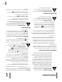
WARNING: This symbol points out important safety instructions which, if not followed,
could endanger the personal safety and/or property of yourself and others. Read and follow
all instructions in this manual before attempting to operate this machine. Failure to comply
with these instructions may result in personal injury.
When you see this symbol. HEED ITS WARNING!
WARNING: Engine Exhaust, some of its constituents, and certain vehicle components
contain or emit chemicals known to State of California to cause cancer and birth defects or
other reproductive harm.
WARNING: Battery posts, terminals, and related accessories contain lead and lead
compounds, chemicals known to the State of California to cause cancer and reproductive
harm. Wash hands after handling.
DANGER: This machine was built to be operated according to the safe operation practices in
this manual. As with any type of power equipment, carelessness or error on the part of the
operator can result in serious injury. This machine is capable of amputating fingers, hands,
toes and feet and throwing objects. Failure to observe the following safety instructions could
result in serious injury or death.

4 Section 2 — important Safe operation practiceS
b. Be alert and turn machine off if a child enters the
area.
c. Before and while backing, look behind and down for
small children.
d. Never carry children, even with the blade(s) shut off.
They may fall off and be seriously injured or interfere
with safe machine operation.
e. Use extreme care when approaching blind corners,
doorways, shrubs, trees or other objects that may
block your vision of a child who may run into the
path of the machine.
f. To avoid back-over accidents, always disengage
the cutting blade(s) before shifting into Reverse.
If equipped, the “Reverse Caution Mode” should
not be used when children or others are around.
g. Keep children away from hot or running engines.
They can suffer burns from a hot muffler.
h. Remove key when machine is unattended to
prevent unauthorized operation.
2. Never allow children under 14 years of age to operate this
machine. Children 14 and over should read and understand
the instructions and safe operation practices in this manual
and on the machine and should be trained and supervised
by an adult.
Towing
1. Tow only with a machine that has a hitch designed for
towing. Do not attach towed equipment except at the
hitch point.
2. Follow the manufacturers recommendation for weight
limits for towed equipment and towing on slopes.
3. Never allow children or others in or on towed equipment.
4. On slopes, the weight of the towed equipment may cause
loss of traction and loss of control.
5. Always use extra caution when towing with a machine
capable of making tight turns (e.g. “zero-turn” ride-on
mower). Make wide turns to avoid jack-knifing.
6. Travel slowly and allow extra distance to stop.
7. Do not shift to neutral and coast downhill.
Service
Safe Handling of Gasoline:
1. To avoid personal injury or property damage use extreme
care in handling gasoline. Gasoline is extremely
flammable and the vapors are explosive. Serious
personal injury can occur when gasoline is spilled on
yourself or your clothes which can ignite. Wash your skin
and change clothes immediately.
a. Use only an approved gasoline container.
b. Never fill containers inside a vehicle or on a truck
or trailer bed with a plastic liner. Always place
containers on the ground away from your vehicle
before filling.
c. When practical, remove gas-powered equipment
from the truck or trailer and refuel it on the ground.
If this is not possible, then refuel such equipment on
a trailer with a portable container, rather than from a
gasoline dispenser nozzle.
d. Keep the nozzle in contact with the rim of the fuel
tank or container opening at all times until fueling is
complete. Do not use a nozzle lock-open device.
e. Extinguish all cigarettes, cigars, pipes and other
sources of ignition.
f. Never fuel machine indoors.
g. Never remove gas cap or add fuel while the engine
is hot or running. Allow engine to cool at least two
minutes before refueling.
h. Never over fill fuel tank. Fill tank to no more than ½
inch below bottom of filler neck to allow space for
fuel expansion.
i. Replace gasoline cap and tighten securely.
j. If gasoline is spilled, wipe it off the engine and
equipment. Move machine to another area. Wait 5
minutes before starting the engine.
k. To reduce fire hazards, keep machine free of grass,
leaves, or other debris build-up. Clean up oil or fuel
spillage and remove any fuel soaked debris.
l. Never store the machine or fuel container inside
where there is an open flame, spark or pilot light
as on a water heater, space heater, furnace, clothes
dryer or other gas appliances.
m. Allow a machine to cool at least five minutes before
storing.
General Service
1. Never run an engine indoors or in a poorly ventilated area.
Engine exhaust contains carbon monoxide, an odorless,
and deadly gas.
2. Before cleaning, repairing, or inspecting, make certain the
blade(s) and all moving parts have stopped. Disconnect the
spark plug wire and ground against the engine to prevent
unintended starting.
3. Periodically check to make sure the blades come to
complete stop within approximately (5) five seconds after
operating the blade disengagement control. If the blades
do not stop within the this time frame, your machine
should be serviced professionally by an authorized Service
Dealer.
4. Check brake operation frequently as it is subjected to wear
during normal operation. Adjust and service as required.
5. Check the blade(s) and engine mounting bolts at frequent
intervals for proper tightness. Also, visually inspect blade(s)
for damage (e.g., excessive wear, bent, cracked). Replace
the blade(s) with the original equipment manufacturer’s
(O.E.M.) blade(s) only, listed in this manual. “Use of parts
which do not meet the original equipment specifications
may lead to improper performance and compromise
safety!”

5Section 2 — important Safe operation practiceS
16. Mow only in daylight or good artificial light.
17. Never carry passengers.
18. Disengage blade(s) before shifting into reverse. Back up
slowly. Always look down and behind before and while
backing to avoid a back-over accident.
19. Slow down before turning. Operate the machine smoothly.
Avoid erratic operation and excessive speed.
20. Disengage blade(s), set parking brake, stop engine and
wait until the blade(s) come to a complete stop before
removing grass catcher, emptying grass, unclogging chute,
removing any grass or debris, or making any adjustments.
21. Never leave a running machine unattended. Always turn
off blade(s), place transmission in neutral, set parking
brake, stop engine and remove key before dismounting.
22. Use extra care when loading or unloading the machine into
a trailer or truck. This machine should not be driven up or
down ramp(s), because the machine could tip over, causing
serious personal injury. The machine must be pushed
manually on ramp(s) to load or unload properly.
23. Muffler and engine become hot and can cause a burn. Do
not touch.
24. Check overhead clearances carefully before driving under
low hanging tree branches, wires, door openings etc.,
where the operator may be struck or pulled from the
machine, which could result in serious injury.
25. Disengage all attachment clutches, depress the brake
pedal completely and shift into neutral before attempting
to start engine.
26. Your machine is designed to cut normal residential grass of
a height no more than 10”. Do not attempt to mow through
unusually tall, dry grass (e.g., pasture) or piles of dry leaves.
Dry grass or leaves may contact the engine exhaust and/or
build up on the mower deck presenting a potential fire
hazard.
27. Use only accessories and attachments approved for this
machine by the machine manufacturer. Read, understand
and follow all instructions provided with the approved
accessory or attachment.
28. Data indicates that operators, age 60 years and above, are
involved in a large percentage of riding mower-related
injuries. These operators should evaluate their ability
to operate the riding mower safely enough to protect
themselves and others from serious injury.
29. If situations occur which are not covered in this manual, use
care and good judgment. Contact your customer service
representative for assistance.
Slope Operation
Slopes are a major factor related to loss of control and tip-over
accidents which can result in severe injury or death. All slopes
require extra caution. If you cannot back up the slope or if you
feel uneasy on it, do not mow it.
For your safety, use the slope gauge included as part of this
manual to measure slopes before operating this machine on
a sloped or hilly area. If the slope is greater than 15 degrees as
shown on the slope gauge, do not operate this machine on that
area or serious injury could result.
Do:
1. Mow up and down slopes, not across. Exercise extreme
caution when changing direction on slopes.
2. Watch for holes, ruts, bumps, rocks, or other hidden
objects. Uneven terrain could overturn the machine. Tall
grass can hide obstacles.
3. Use slow speed. Choose a low enough speed setting so
that you will not have to stop or shift while on the slope.
Tires may lose traction on slopes even though the brakes
are functioning properly. Always keep machine in gear
when going down slopes to take advantage of engine
braking action.
4. Follow the manufacturer’s recommendations for wheel
weights or counterweights to improve stability.
5. Use extra care with grass catchers or other attachments.
These can change the stability of the machine.
6. Keep all movement on the slopes slow and gradual. Do
not make sudden changes in speed or direction. Rapid
engagement or braking could cause the front of the
machine to lift and rapidly flip over backwards which could
cause serious injury.
7. Avoid starting or stopping on a slope. If tires lose traction,
disengage the blade(s) and proceed slowly straight down
the slope.
Do Not:
1. Do not turn on slopes unless necessary; then, turn slowly
and gradually downhill, if possible.
2. Do not mow near drop-offs, ditches or embankments. The
mower could suddenly turn over if a wheel is over the edge
of a cliff, ditch, or if an edge caves in.
3. Do not try to stabilize the machine by putting your foot on
the ground.
4. Do not use a grass catcher on steep slopes.
5. Do not mow on wet grass. Reduced traction could cause
sliding.
6. Do not shift to neutral and coast downhill. Over-speeding
may cause the operator to lose control of the machine
resulting in serious injury or death.
7. Do not tow heavy pull behind attachments (e.g. loaded
dump cart, lawn roller, etc.) on slopes greater than 5
degrees. When going down hill, the extra weight tends to
push the tractor and may cause you to loose control (e.g.
tractor may speed up, braking and steering ability are
reduced, attachment may jack-knife and cause tractor to
overturn).
Children
1. Tragic accidents can occur if the operator is not alert to the
presence of children. Children are often attracted to the
machine and the mowing activity. They do not understand
the dangers. Never assume that children will remain where
you last saw them.
a. Keep children out of the mowing area and in
watchful care of a responsible adult other than the
operator.

6 Section 2 — important Safe operation practiceS
6. Mower blades are sharp. Wrap the blade or wear gloves,
and use extra caution when servicing them.
7. Keep all nuts, bolts, and screws tight to be sure the
equipment is in safe working condition.
8. Never tamper with the safety interlock system or other
safety devices. Check their proper operation regularly.
9. After striking a foreign object, stop the engine, disconnect
the spark plug wire(s) and ground against the engine.
Thoroughly inspect the machine for any damage. Repair
the damage before starting and operating.
10. Never attempt to make adjustments or repairs to the
machine while the engine is running.
11. Grass catcher components and the discharge cover are
subject to wear and damage which could expose moving
parts or allow objects to be thrown. For safety protection,
frequently check components and replace immediately
with original equipment manufacturer’s (O.E.M.) parts only,
listed in this manual. “Use of parts which do not meet the
original equipment specifications may lead to improper
performance and compromise safety!”
12. Do not change the engine governor settings or over-speed
the engine. The governor controls the maximum safe
operating speed of the engine.
13. Maintain or replace safety and instruction labels, as
necessary.
14. Observe proper disposal laws and regulations for gas, oil,
etc. to protect the environment.
15. According to the Consumer Products Safety Commission
(CPSC) and the U.S. Environmental Protection Agency (EPA),
this product has an Average Useful Life of seven (7) years,
or 270 hours of operation. At the end of the Average Useful
Life have the machine inspected annually by an authorized
service dealer to ensure that all mechanical and safety
systems are working properly and not worn excessively.
Failure to do so can result in accidents, injuries or death.
Do not modify engine
To avoid serious injury or death, do not modify engine in any
way. Tampering with the governor setting can lead to a runaway
engine and cause it to operate at unsafe speeds. Never tamper
with factory setting of engine governor.
Notice Regarding Emissions
Engines which are certified to comply with California and federal
EPA emission regulations for SORE (Small Off Road Equipment)
are certified to operate on regular unleaded gasoline, and
may include the following emission control systems: Engine
Modification (EM), Oxidizing Catalyst (OC), Secondary Air
Injection (SAI) and Three Way Catalyst (TWC) if so equipped.
When required, models are equipped with low permeation fuel
lines and fuel tanks for evaporative emission control. California
models may also include a carbon canister. Please contact
Customer Support for information regarding the evaporative
emission control configuration for your model.
Spark Arrestor
WARNING! This machine is equipped with an
internal combustion engine and should not be used
on or near any unimproved forest-covered,
brushcovered or grass-covered land unless the
engine’s exhaust system is equipped with a spark
arrester meeting applicable local or state laws (if
any).
If a spark arrester is used, it should be maintained in effective
working order by the operator.
A spark arrester for the muffler is available through your nearest
engine authorized service dealer.
WARNING! Your Responsibility—Restrict the use of this power machine to persons who read, understand and
follow the warnings and instructions in this manual and on the machine.
SAVE THESE INSTRUCTIONS!

7Section 2 — important Safe operation practiceS
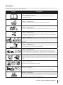
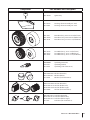
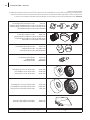
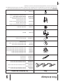
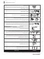
Safety Symbols
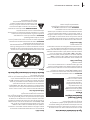
This page depicts and describes safety symbols that may appear on this product. Read, understand, and follow all instructions on the
machine before attempting to assemble and operate.
Symbol Description
READ THE OPERATOR’S MANUAL(S)
Read, understand, and follow all instructions in the manual(s) before attempting to
assemble and operate
DANGER — ROTATING BLADES
Never carry passengers. Never carry children, even with the blades off.
DANGER — ROTATING BLADES
Always look down and behind before and while backing to avoid a back-over accident.
DANGER — ROTATING BLADES
Do not put hands or feet near rotating parts or under the cutting deck. Contact with
the blade(s) can amputate hands and feet. Be sure blades and engine are stopped before
placing hands or feet near blades.
DANGER — BYSTANDERS
Mowing in reverse is not recommended. Do not mow when children or others are around.
Keep bystanders, helpers, children and pets at least 75 feet from the machine while it is in
operation.
DANGER — THROWN OBJECTS
This machine may pick up and throw and objects which can cause serious personal injury.
Remove objects which could be thrown by the blades.
DANGER — SLOPE OPERATION
Go up and down slopes, not across. Use extra caution on slopes. Do not mow slopes
greater than 15 degrees. Avoid sudden turns. Use low speed. Do not operate machine
where it could tip or slip. If machine stops going uphill, stop blades and back down slowly.
DANGER — ROTATING BLADES
Before leaving operator’s position, disengage blades, engage parking brake, shut off engine
and remove key. Keep safety devices (guards, shields, switches, etc.) in place and in working
order.
DANGER — HOT SURFACES
Allow machine to cool before fueling or storing.
max10"
DANGER — HOT SURFACES
Do not drive through piles of dry leaves or tall dry grass. Keep machine free of debris.
WARNING — HOT SURFACES
Operation of this equipment may create sparks that can start fires around dry vegetation.
A spark arrestor may be required. The operator should contact local fire agencies for laws
or regulations relating to fire prevention requirements.

8 Section 2 — important Safe operation practiceS
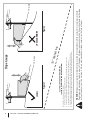
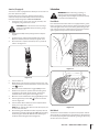
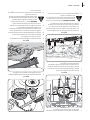
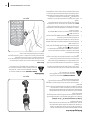
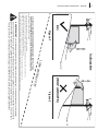
WARNING! Slopes are a major factor related to tip-over and roll-over accidents which can result in severe injury or death.
Do not operate machine on slopes in excess of 15 degrees. All slopes require extra caution. If you cannot back up the slope
or if you feel uneasy on it, do not mow it. Always mow up and down slopes, never across the face of slopes.
(TOO STEEP)
USE THIS SLOPE GAUGE TO DETERMINE
IF A SLOPE IS TOO STEEP FOR SAFE OPERATION!
T
o check the slop
e, proceed as follows:
1. Remov
e this page and
fold along the dashed line.
2. Locate a vertical object on or behind the slope (e.g. a pole, building, fence, tree, etc.)
3. Alig
n either side of the slope gauge with the obje
ct (See Figure 1 and Figure 2 ).
4. A
djust gauge up or d
own until the left corner touches the slope (See Figure 1 and Figure 2).
5. If there is a gap below the gauge, the slope is too steep for safe operation (See Figure 2 above).
15° dashed line
Slope Gauge
Figure 2Figure 1
15° Slope
15° Slope
(OK)

Assembly & Set-Up
3
9
NOTE: This Operator’s Manual covers several models. Tractor
features may vary by model. Not all features in this manual are
applicable to all tractor models and the tractor depicted may
differ from yours.
NOTE: All references in this manual to the left or right side and
front or back of the tractor are from the operating position only.
Exceptions, if any, will be specified.
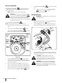
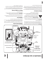
Tractor Preparation
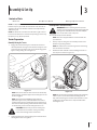
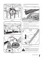
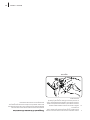
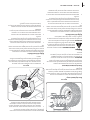
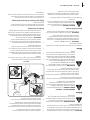
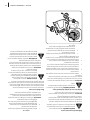
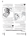
Manually Moving the Tractor
1. Engage the transmission bypass rod to move the tractor
manually without starting it. The transmission bypass rod is
located on the rear of the tractor, on the frame. Engage the
bypass rod by pulling out. See Figure 3-1.
Figure 3-1
NOTE: If the tractor will not move or does not move freely
when pushing check if the bypass lever is fully open or the
brake is engaged.
NOTE: The transmission will NOT engage when the
hydrostatic bypass rod is pulled out. Return the rod to its
normal position prior to operating the tractor. If the tractor
will not move when pushing on the forward/reverse pedals,
or moves slowly, check to see of the bypass valve is on.
CAUTION: Never tow your tractor. Towing the
tractor with the rear wheels on the ground may
cause severe damage to the transmission.
2. Disengage the bypass rod by pushing the rod back in after
moving the tractor. See Figure 3-1.
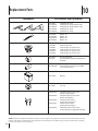
Contents of Crate
• One Tractor • One Operator’s Manual • One Engine Operator’s Manual
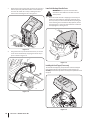
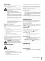
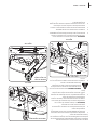
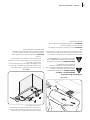
Install Operator’s Seat (If necessary)
WARNING! Before operating the tractor, make
sure the seat is engaged in the seat-stop. Engage the
parking brake. Stand behind the machine and pull
back on seat until it clicks into place.
To install the seat proceed as follows:
NOTE: The seat is shipped with the seat switch and seat
pan attached.
1. Cut any straps securing the seat assembly to the tractor.
Remove any packing material.
NOTE: Be careful not to cut the wiring harness connecting
the seat and the seat switch.
2. Remove the two shoulder screws and flange lock nuts in
the seat pan as shown in Figure 3-2.
Figure 3-2
NOTE: Be sure that the nylon flange bearings (if equipped)
remain in place on the seat bracket mounting holes. If
they come out during the removal of the shoulders screws
and flange lock nuts make sure to replace them before
installing the seat.

10 Section 3— ASSembly & Set-Up
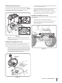
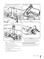
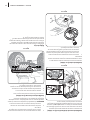
3. Rotate the seat into position and secure the seat into place
with the previously removed shoulder screws and flange
lock nuts. Be careful not to crimp or damage the wire
harness while installing the seat. See Figure 3-3.
Figure 3-3
4. Using the harness clip attached to the harness, secure the
excess wire to the fender by snapping the harness clip in
place as shown in Figure 3-4.
Figure 3-4
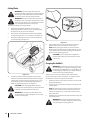
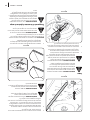
Lower Deck Discharge Chute Deflector
WARNING! Never operate the mower deck
without the chute deflector installed and in the
down position.
1. Check the mower deck for a shipping brace that may be
holding the chute deflector upward for shipment. If the
brace is present, it must be removed before operating the
tractor. Holding the chute deflector fully upward, remove
the shipping brace. Lower the chute deflector and discard
the shipping brace. See Figure 3-5.
Figure 3-5
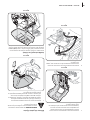
Installing the Hood Topper (If necessary)
To install the hood topper (1), line up the holes on the hood topper
(1) up with the tabs (2) in the hood frame as shown in Figure 3-6.
Carefully insert the tabs (2) into the hood topper and pull back to lock
into place.
1
2
2
2
2
Figure 3-6

11Section 3 — ASSembly & Set-Up
Installing the Dash Cap (If necessary)
To install the dash cap (1), line up the tabs (2) on the dash cap (1)
with the holes in the upper dash as shown in Figure 3-7. Carefully
slide the tabs (2) into the holes in the upper dash and push
forward on the dash cap (1) to lock into place.
1
2
2
2
2
3
Figure 3-7
NOTE: Be sure to press on the lower part of the dash cap
(3) facing the operator position to ensure the lower tabs on
the dash cap are in place.
Installing the Steering Wheel (If necessary)
The hardware for attaching the steering wheel has been packed
within the steering wheel, beneath the steering wheel cap.
Carefully pry off the steering wheel cap and remove the hardware.
1. With the wheels of the tractor pointing straight forward, align
the steering wheel by using the center-line on the front of the
steering wheel pointing straight ahead and the flat section of
the steering wheel facing toward the seat, place the steering
wheel over the steering shaft. See Figure 3-8.
Center-Line
Flat
Figure 3-8
2. Secure the steering wheel with the hex bolt from under the
cap and torque to 18-22 ft./lbs.
3. Place the steering wheel cap over the center of the steering
wheel and push downward until it “clicks” into place.
NOTE: The bolt securing the steering wheel has thread
locker applied to it, so if it is removed, it is recommended
that the bolt be replaced or thread lock re-applied.
Installing the Front Bumper (If necessary)
The hardware for attaching the front bumper is shipped installed
into the bumper.
1. Remove the four hex screws from the bumper.
2. Position the bumper brackets to the inside of the tractor’s
frame and secure it in place with the four hex flange
screws. See Figure 3-9.
Figure 3-9

12 Section 3— ASSembly & Set-Up
Adjusting the Seat
To adjust the position of the seat, lift the seat adjustment lever
up. Slide the seat forward or rearward to the desired position;
then release the adjustment lever. Make sure seat is locked into
position before operating the tractor. See Figure 3-10.
Figure 3-10
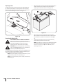
Connecting the Battery Cables
CALIFORNIA PROPOSITION 65 WARNING!
Battery posts, terminals, and related accessories
contain lead and lead compounds, chemicals known
to the State of California to cause cancer and
reproductive harm. Wash hands after handling.
CAUTION: When attaching battery cables, always
connect the POSITIVE (Red) wire to its terminal first,
followed by the NEGATIVE (Black) wire.
For shipping reasons, both battery cables on your equipment may
have been left disconnected from the terminals at the factory. To
connect the battery cables, proceed as follows:
NOTE: The positive battery terminal is marked Pos. (+). The
negative battery terminal is marked Neg. (–).
NOTE: If the positive battery cable is already attached, skip
ahead to step 2.
1. Remove the plastic cover, if present, from the positive battery
terminal and attach the red cable to the positive battery
terminal (+) with the bolt and hex nut. See Figure 3-11.
Figure 3-11
2. Remove the plastic cover, if present, from the negative
battery terminal and attach the black cable to the negative
battery terminal (–) with the bolt and hex nut. See Figure
3-11.
3. Position the red rubber boot over the positive battery
terminal to help protect it from corrosion.
NOTE: If the battery is put into service after the date shown
on top/side of battery, charge the battery as instructed
in the Service section your Operator’s Manual prior to
operating the tractor.

13Section 3 — ASSembly & Set-Up
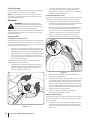
Checking Tire Pressure
WARNING! Equal tire pressure should be
maintained at all times. Refer to the tire sidewall for
proper pressure.
The tires on your tractor may be over-inflated for shipping
purposes. Reduce the tire pressure before operating the tractor.
Check the sidewall of tire for maximum p.s.i.
NOTE: Equal tire pressure is critical for level cutting deck
performance.
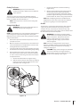
Setting the Deck Wheels
WARNING!: Keep hands and feet away from the
discharge opening of the cutting deck.
NOTE: The deck wheels are an anti-scalp feature of the deck and
are not designed to support the weight of the cutting deck.
Move the tractor on a firm and level surface, preferably pavement,
and proceed as follows:
1. Check the tire pressure, make sure the pressure is correct
and equal on all tires.
2. Make sure the deck is level, both front-to-back and side-to-
side. See the Maintenance & Adjustments section for deck
leveling information and instructions.
3. Select the height position of the cutting deck by placing the
deck lift lever in the normally desired mowing height setting.
4. Check the wheels for contact or excessive clearance with
the surface below. The deck wheels should have between
¼” and ½” clearance above the ground. Proceed as follows
to adjust the wheels:
a. Raise the deck lift handle to its highest setting.
b. Remove the front and rear deck wheels by removing
the flange lock nuts and shoulder bolts that secure
them to the deck. See Figure 3-12.
Figure 3-12
c. Place the deck lift lever in the desired mowing
height setting.
d. Reinsert the shoulder bolt (with each deck wheel)
into the index hole that leaves approximately
½-inch between the bottom of the wheel and the
pavement. Tighten the flange lock nut and shoulder
bolt to between 25-30 ft-lbs using a torque wrench.
NOTE: Refer to Adjusting the Deck in the Maintenance
& Adjustments section of this manual for more detailed
instructions regarding various deck adjustments.
Gas & Oil
The fuel tank is located at the outer/left of the dash and holds
3 gallons of gas. Remove the fuel cap by turning it counter-
clockwise. Use only clean, fresh (no more than 30 days old),
unleaded gasoline. Fill the tank no higher than the bottom of the
fill neck to allow space for fuel expansion.
WARNING! Use extreme care when handling
gasoline. Gasoline is extremely flammable and the
vapors are explosive. Never fuel the machine
indoors or while the engine is hot or running.
Extinguish cigarettes, cigars, pipes and other
sources of ignition.
NOTE: Your tractor is shipped with oil in the engine.
However, you MUST check the oil level before operating.
See the Service section for instructions on checking,
adding and changing oil.
CAUTION: Always check the engine oil level before
each use as instructed in the engine operator’s
manual. Add oil as necessary. Failure to do so may
result in serious damage to your engine

Controls & Features
4
14
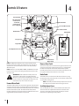
NOTE: This Operator’s Manual covers several models. Tractor
features may vary by model. Not all features in this manual are
applicable to all tractor models and the tractor depicted may
differ from yours.
NOTE: References to LEFT, RIGHT, FRONT, and REAR indicate that
position on the tractor when facing forward while seated in the
operator’s seat.
WARNING! Read and follow all safety rules and
instructions in this manual, including the entire
Operation section, before attempting to operate this
machine. Failure to comply with all safety rules and
instructions may result in personal injury.
Forward Drive Pedal
The forward drive pedal is located on the right side of the machine,
along the running board. Press the forward drive pedal forward to
cause the tractor to travel forward. Ground speed is also controlled
with the forward drive pedal. The further forward the pedal is
pivoted, the faster the tractor will travel. The pedal will return to its
original/neutral position when it’s not pressed.
Reverse Drive Pedal
The reverse drive pedal is located on the right side of the tractor
along the running board. Ground speed is also controlled with
the reverse drive pedal. The further downward the pedal is
pivoted, the faster the tractor will travel. The pedal will return to
its original/neutral position when it’s not pressed.
Brake Pedal
The brake pedal is located on the left side of the tractor, along
the running board. The brake pedal can be used for sudden stops
or setting the parking brake.
NOTE: The brake pedal must be fully depressed to activate
the safety interlock switch when starting the tractor.
Seat Adjustment Lever
The seat adjustment lever is located below the left of the seat.
The lever allows for adjustment forward or backward of the
operator’s seat. Refer to the Assembly & Set-Up section for
instructions on adjusting the seat position.
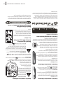
Fuel Tank Cap
Throttle/Choke
Control Lever
or Throttle
Control Lever
(If so equipped)
Brake Pedal
Storage Tray
Cup Holder
Seat Adjustment Lever
Transmission
Bypass Rod
Deck Lift Lever
PTO Switch (If
so equipped)
Reverse Drive Pedal
Forward Drive Pedal
Park Brake/Cruise
Control Lever
Ignition Module
Choke Control
(If so equipped)
Manual PTO
(If so equipped)
PTO Handle
Hour Meter

15Section 4 — controlS & FeatureS
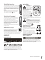
Throttle/Choke Control Lever
The throttle/choke control is located on the left side of
the tractor’s dash panel. This lever controls the speed
of the engine and, when pushed all the way forward,
closes the choke for cold starting. When set in a given
position, the throttle will maintain a uniform engine
speed.
NOTE: When operating the tractor with the cutting
deck engaged, be certain that the throttle/choke
control is always in the FAST position.
Throttle Control (If so equipped)
The throttle control is located on the left side of the
tractor’s dash panel. When set in a given position, a
uniform engine speed will be maintained.
Push the throttle control handle forward to increase
the engine speed. The tractor is designed to operate
with the throttle control in the fast position (full
throttle) when the tractor is being driven and the
mower deck is engaged.
Pull the throttle control handle rearward to decrease
the engine speed.
Choke Control (If so equipped)
On some models, moving the throttle lever all the
way forward activates the engine’s choke control.
On all other models, the choke control can be
found on the right side of the dash panel and is
activated by pulling the knob outward. Activating the choke
control closes the choke plate on the carburetor and aids in
starting the engine.
Deck Lift Lever
Models with Electric PTO
Models with Manual PTO
The lift lever is located in the right fender and is used to raise
and lower the deck. Pull the handle to the left out of the index
notch and push downward to lower the deck, or pull upward to
raise the deck. When the desired height is attained, move the lift
handle to the right until fully in the index notch.
Ignition Module
WARNING! Never
leave a running
machine unattended.
Always disengage
PTO, set parking brake, stop
engine and remove key to prevent
unintended starting.
To start the engine, insert the
key into the ignition switch and
turn clockwise to the START
position. Release the key into the
NORMAL MOWING MODE
position once the engine has fired.
To stop the engine, turn the ignition key counterclockwise to the
STOP position.
CAUTION: Prior to operating the tractor, refer to
both Safety Interlock Switches and Starting The
Engine in the Operation section of this manual for
detailed instructions regarding the Ignition Switch
Module and operating the tractor in REVERSE
CAUTION MODE .
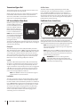
Power Take-Off (PTO) Switch
(Models with Electric PTO)
The PTO switch is located on the dash panel
to the right of the LCD Service Minder & Hour
Meter.
Activating the PTO engages power to the
cutting deck or other (separately available)
attachments. See the Operation section for
information and isntructions on using the PTO.
PTO/Blade Engage Handle
(Models with Manual PTO)
The PTO/blade engage handle is located on the right fender.
Activating the PTO engages power to the cutting deck or other
(separately available) attachments. See the Operation section for
information and isntructions on using the PTO.

16 Section 4— controlS & FeatureS
Transmission Bypass Rod
The transmission bypass rod is located at the rear of the tractor
on the lower right section of the frame.
When engaged, the rod opens a bypass within the hydrostatic
transmissions, which allows the tractor to be pushed short
distances by hand. Refer to the Assembly & Set-Up section for
instructions on using the bypass feature.
LCD Service Minder & Hour Meter
When the ignition key is rotated
out of the STOP position but
not into the START position, the
LCD Service Minder and Hour
Meter will briefly display the
battery voltage, followed by the
tractor’s accumulated hours.
NOTE: Hours of tractor operation
are recorded any time the ignition
key is rotated out of the STOP
position, regardless of whether
the engine is started.
The LCD Service Minder will remind the operator of maintenance
intervals for changing the engine oil, air filter service, low engine
and low battery warnings.
Change Oil
The LCD will display the letters “CHG”, followed by the letters
“OIL”, followed by the letters “SOON”, then finally followed by the
meter’s accumulated time. “CHG/OIL/SOON/TIME” will alternate
on the display for 7 minutes after the meter reaches 50 hours.
This oil service minder interval will occur every 50 hours. Before
the interval expires, change the engine oil as instructed in the
Maintenance section of the Engine Operator’s Manual
Low Oil
The letters “LO” followed by the letters “OIL”, then followed by
the meter’s accumulated time will indicate the tractor is low on
oil. When an engine is not running and immediately after the
engine is started the oil pressure may be low. This can trigger the
“LO” “OIL” text. This is normal. If the low oil indication persists
stop the tractor immediately and check the engine oil level as
instructed in the Engine Operator’s Manual.
NOTE: The “LOW OIL” function only works if the engine is
equipped with an oil pressure switch.
Low Battery
At startup, the battery voltage is briefly displayed then changes
to accumulated hours. The letters “LO” will display followed by
the letters “BATT” and then followed by the meter’s accumulated
time. “LO/BATT/TIME” is displayed on the LCD when the voltage
drops below 11.5 volts. When this occurs, the battery is in need
of a charge or the engine’s charging system is not generating
sufficient amperage. Charge the battery as instructed in the
Service section of this manual or have the charging system
checked by your local service dealer.
Air Filter Service
The letters “CLN” will display, followed by the letters “AIR”,
followed by “FILT”, then followed by the meter’s accumulated
time. “CLN/AIR/FILT/TIME” will alternate on the display for 7
minutes after the meter reaches 25 hours. This air filter service
minder time interval will be every 25 hours. On intervals that are
common with oil service, the oil message will be displayed first
followed by the air filter message.
Park Brake/Cruise Control Lever
Located in the center of the tractor’s dash panel below the steering
wheel, the park brake/cruise control lever is used to engage the
parking brake and the cruise control Refer to the Operation section
of this manual for detailed instructions regarding the parking brake.
NOTE: The parking brake must be set if the operator
leaves the seat with the engine running or the engine will
automatically shut off.
NOTE: Cruise control can NOT be engaged at the tractor’s
fastest ground speed. If the operator should attempt to do
so, the tractor will automatically decelerate to the fastest
optimal mowing ground speed.
WARNING! Never leave a running machine
unattended. Always disengage the PTO, set the
parking brake, stop the engine and remove the key
to prevent unintended starting.

Operation
5
17
WARNING! Avoid serious injury or death. Go up
and down slopes, not across. Avoid sudden turns.
Do not operate the tractor where it could slip or tip.
If machine stops going uphill, stop the PTO and back
down the hill safely. Keep safety devices (guards,
shields and switches) in place and working. Remove
objects that could be thrown by the blades. Know
the location and function of all controls. Be sure the
blades and the engine are stopped before placing
hands or feet near blades. Before leaving the
operator’s position, disengage the PTO, engage
parking brake, shut off the engine and remove the key.
Safety Interlock Switches
This tractor is equipped with a safety interlock system for the
protection of the operator. If the interlock system should ever
malfunction, do not operate tractor. Contact your Cub Cadet dealer.
• The safety interlock system prevents the engine from
cranking or starting unless the parking brake is engaged,
and the PTO is in the DISENGAGED (OFF) position.
• The engine will automatically shut off if the operator leaves
the seat before engaging the parking brake.
• The PTO clutch will automatically shut off if the operator
leaves the tractor’s seat with the PTO in the ENGAGED
(ON) position, regardless of whether the parking brake is
engaged.
• With the ignition key in the NORMAL MOWING
position, the PTO clutch will automatically shut off if the
PTO is moved into the ENGAGED (ON) position with the
drive pedal in position for reverse travel.
WARNING! Do not operate the tractor if the
interlock system is malfunctioning. This system was
designed for your safety and protection.
Starting the Engine
WARNING! Do not operate the tractor if the
interlock system is malfunctioning. This system was
designed for your safety and protection.
NOTE: Refer to the Assembly & Set-up section of this manual for
Gasoline and Oil fill-up instructions.
1. Insert the tractor key into the ignition switch module.
2. Place the PTO in the DISENGAGED (OFF) position.
3. Engage the tractor’s parking brake.
4. Pull the choke control (if so equipped) up into the CHOKE
position or move the throttle/choke control (if so equipped)
into the CHOKE position.
NOTE: If the engine is warmed up, it may not be necessary
to place the choke in choke position.
5. Turn the ignition key clockwise to the START position.
After the engine starts, release the key. It will return to the
NORMAL MOWING position.
CAUTION: Do NOT hold the key in the START
position for longer than ten seconds at a time. Doing
so may cause damage to your engine’s electric
starter.
6. After the engine starts, move the throttle/choke control (if
so equipped) down into the FAST position or push the
choke control (if so equipped) down into the OFF position.
NOTE: Do NOT leave the choke control on while operating
the tractor. Doing so will result in a “rich” fuel mixture and
cause the engine to run poorly.
NOTE: When operating the tractor be certain that the
throttle lever is always in the FAST position. Operating
with the throttle at less than full throttle may lead to
shortened battery life.
Stopping the Engine
WARNING! If you strike a foreign object, stop the
engine and disconnect the spark plug wire(s).
Thoroughly inspect the machine for any damage.
Repair the damage before restarting and operating
1. If the blades are ENGAGED (ON), place the PTO is in the
DISENGAGED (OFF) position.
2. Place the throttle near the SLOW position
3. Engage the parking brake.
4. Turn the ignition key counterclockwise to the STOP
position.
5. Remove the key from the ignition switch to prevent
unintended starting.

18 Section 5— operation
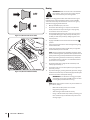
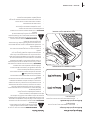
Reverse Caution Mode
The REVERSE CAUTION MODE position of the ignition
module allows the tractor to be operated in reverse with the
blades (PTO) engaged.
NOTE: Mowing in reverse is not recommended.
WARNING! Use extreme caution while operating
the tractor in the REVERSE CAUTION MODE .
Always look down and behind before and while
backing. Do not operate the tractor when children
or others are around. Stop the tractor immediately if
someone enters the area.
To use the REVERSE CAUTION MODE :
NOTE: The operator MUST be seated in the tractor seat.
1. Start the engine as previously instructed on the previous
page.
2. Turn the key from the NORMAL MOWING (Green)
position to the REVERSE CAUTION MODE (Yellow)
position of the ignition module. See Figure 5-1.
Start
position
Indicator
Light
Reverse
Push
Button
Normal
Driving
Mode
Stop
position
Reverse
Caution
Mode
Position
Figure 5-1
3. Press the REVERSE PUSH BUTTON at the top, right
corner of the ignition module. The red indicator light at
the top, left corner of the ignition module will be ON while
activated. See Figure 5-1.
4. Once activated (indicator light ON), the tractor can be
driven in reverse with the cutting blades (PTO) engaged.
5. Always look down and behind before and while backing to
make sure no children are around. After resuming forward
motion, return key to the NORMAL MOWING position.
6. The REVERSE CAUTION MODE will remain activated
until:
a. The key is placed in either the NORMAL MOWING
position or STOP position or
b. The operator leaves the seat.
Driving The Tractor
WARNING! Avoid sudden starts, excessive speed
and sudden stops.
1. Lightly press the brake pedal to release the parking brake.
Move the throttle into the FAST position.
2. To travel FORWARD, slowly press the forward drive pedal
forward until the desired speed is achieved. See Figure 5-2.
Figure 5-2
3. To travel in REVERSE, check that the area behind is clear then
slowly depress the reverse drive pedal until the desired speed
is achieved. See Figure 5-2.
CAUTION: Do NOT attempt to change the
direction of travel when the tractor is in motion.
Always bring the tractor to a complete stop before
changing from forward to reverse or vice versa.
WARNING! Do not leave the seat of the tractor
without first placing the PTO in the DISENGAGED
(OFF) position and engaging the parking brake. If
leaving the tractor unattended, also turn the engine
off and remove the ignition key.

19Section 5 — operation
Driving On Slopes
Refer to the SLOPE GAUGE on page 8 to help determine slopes
where you may operate the tractor safely.
WARNING! Do not mow on inclines with a slope in
excess of 15 degrees (a rise of approximately 2-⁄
feet every 10 feet). The tractor could overturn and
cause serious injury.
• Mow up and down slopes, NEVER across.
• Exercise extreme caution when changing direction on
slopes.
• Watch for holes, ruts, bumps, rocks, or other hidden
objects. Uneven terrain could overturn the machine.
Tall grass can hide obstacles.
• Avoid turns when driving on a slope. If a turn must
be made, turn down the slope. Turning up a slope
greatly increases the chance of a roll over.
• Avoid stopping when driving up a slope. If it is
necessary to stop while driving up a slope, start up
smoothly and carefully to reduce the possibility of
flipping the tractor over backward.
Engaging the Parking Brake
NOTE: The parking brake must be set if the operator leaves the
seat with the engine running or the engine will automatically
shut off.
To set the parking brake:
1. Press the brake pedal completely down with your left foot
and hold it in that position.
2. Lift the parking brake/cruise control lever upward and hold
it in that position.
3. Remove your foot from the brake pedal.
4. Release pressure from the parking brake/cruise control
lever.
After completing step 3, the brake pedal should remain in the
down position. If it doesn’t, the parking brake is not engaged.
Repeat steps 1-4 to engage.
To disengage the parking brake, lightly press the brake pedal.
WARNING! Never leave a running machine
unattended. Always disengage the PTO, set the
parking brake, stop the engine and remove the key
to prevent unintended starting.
Setting The Cruise Control
WARNING! Never engage the cruise control lever
while traveling in reverse.
To set the cruise control:
1. Slowly press the forward drive pedal with your right foot
until the desired speed is achieved.
2. Lift the parking brake/cruise control lever upward and hold
it in that position.
3. Remove your foot from the forward drive pedal.
4. Release pressure from the parking brake/cruise control
lever .
After completing step 3, the forward drive pedal should remain
in the down position and the tractor will maintain the same
forward speed. If it doesn’t, the cruise control is not engaged.
Repeat steps 1-4 to engage the cruise control.
To disengage the cruise control, lightly press the forward drive
pedal or the brake pedal.
NOTE: Cruise control can not be set at the tractor’s fastest
ground speed. If the operator should attempt to do so, the
tractor will automatically decelerate to the fastest optimal
mowing ground speed.
To change the direction of travel from forward to reverse when
cruise control is engaged, press the brake pedal to disengage
and bring the tractor to a complete stop. Then slowly press the
reverse drive pedal with the ball of your foot to travel in reverse.
Using the Deck Lift Lever
To raise or lower the cutting deck, move the lift lever to the left,
then place it in the notch best suited for your application.
Operating the Headlights
The lamps are ON whenever the ignition key is rotated out of the
STOP position. The lamps turn OFF when the ignition key is
moved to the STOP position.
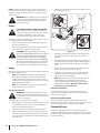
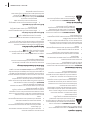
Engaging the PTO
Engaging the PTO transfers power to the cutting deck or other
(separately available) attachments. To engage the PTO:
1. Move the throttle to the FAST position.
Models with Electric PTO:
a. Pull the PTO/Blade Engage knob outward into the
engaged (ON) position. See Figure 5-3.
Models with Manual PTO:
a. Push the PTO/Blade Engage lever forward into the
engaged (ON) position. See Figure 5-4.
NOTE: When operating the tractor be certain that the
throttle is always in the FAST position. Operating with
the throttle at less than full throttle may lead to premature
battery wear and a poor quality cut.
Disengaging the PTO
Models with Electric PTO:
a. Push the PTO switch downward into the
DISENGAGED (OFF) position.
Models with Manual PTO:
a. Pull the PTO handle rearward into the DISENGAGED
(OFF) position.

20 Section 5— operation
ON
OFF
Figure 5-3 (Models with electric PTO)
Figure 5-4 (Models with Manual PTO)
Mowing
WARNING! Make certain the area to be mowed is
free of debris, sticks, stones, wire or other objects
that can be thrown by the rotating blades.
NOTE: Do not engage the mower deck when lowered in grass.
Premature wear and possible failure of the ‘V” belt and PTO
clutch will result. Fully raise the deck or move to a non-grassy
area before engaging the mower deck.
1. Mow up and down slopes, not across.
2. Avoid turns when driving on a slope. If a turn must be
made, turn down the slope. Turning up a slope greatly
increases the chance of a roll over.
3. Avoid stopping when driving up a slope. If it is necessary
to stop while driving up a slope, start up smoothly and
carefully to reduce the possibility of flipping the tractor
over backward
4. Engage the PTO and move the throttle into the FAST
position.
5. Lower the mower deck to the desired height setting using
the deck lift handle.
6. Slowly press the forward drive pedal with your right foot
until the desired speed is achieved.
NOTE: The speed of the tractor will affect the quality of the
mower cut. Mowing at full speed will adversely affect the cut
quality. Control the ground speed with forward drive pedal.
7. When approaching the other end of the strip, slow down
or stop before turning. A U-turn is recommended unless a
pivot or zero turn is required.
8. Align the mower with an edge of the mowed strip and
overlap approximately 3”.
9. Direct the tractor on each subsequent strip to align with a
previously cut strip.
10. To prevent rutting or grooving of the turf, if possible, change
the direction that the strips are mowed by approximately 45°
for the next and each subsequent mowing.
WARNING! Be careful when crossing gravel paths
or driveways. Disengage the PTO and raise the deck
to the highest position before crossing.
NOTE: When stopping the tractor for any reason while on a
grass surface, always:
• Make sure the drive pedals are in neutral.
• Engage the parking brake.
• Shut the engine off and remove the key.
• Doing so will minimize the possibility of having your
lawn ‘‘browned’’ by hot exhaust from your tractor’s
running engine.
La page est en cours de chargement...
La page est en cours de chargement...
La page est en cours de chargement...
La page est en cours de chargement...
La page est en cours de chargement...
La page est en cours de chargement...
La page est en cours de chargement...
La page est en cours de chargement...
La page est en cours de chargement...
La page est en cours de chargement...
La page est en cours de chargement...
La page est en cours de chargement...
La page est en cours de chargement...
La page est en cours de chargement...
La page est en cours de chargement...
La page est en cours de chargement...
La page est en cours de chargement...
La page est en cours de chargement...
La page est en cours de chargement...
La page est en cours de chargement...
La page est en cours de chargement...
La page est en cours de chargement...
La page est en cours de chargement...
La page est en cours de chargement...
La page est en cours de chargement...
La page est en cours de chargement...
La page est en cours de chargement...
La page est en cours de chargement...
La page est en cours de chargement...
La page est en cours de chargement...
La page est en cours de chargement...
La page est en cours de chargement...
La page est en cours de chargement...
La page est en cours de chargement...
La page est en cours de chargement...
La page est en cours de chargement...
La page est en cours de chargement...
La page est en cours de chargement...
La page est en cours de chargement...
La page est en cours de chargement...
La page est en cours de chargement...
La page est en cours de chargement...
La page est en cours de chargement...
La page est en cours de chargement...
La page est en cours de chargement...
La page est en cours de chargement...
La page est en cours de chargement...
La page est en cours de chargement...
La page est en cours de chargement...
La page est en cours de chargement...
La page est en cours de chargement...
La page est en cours de chargement...
La page est en cours de chargement...
La page est en cours de chargement...
La page est en cours de chargement...
La page est en cours de chargement...
-
 1
1
-
 2
2
-
 3
3
-
 4
4
-
 5
5
-
 6
6
-
 7
7
-
 8
8
-
 9
9
-
 10
10
-
 11
11
-
 12
12
-
 13
13
-
 14
14
-
 15
15
-
 16
16
-
 17
17
-
 18
18
-
 19
19
-
 20
20
-
 21
21
-
 22
22
-
 23
23
-
 24
24
-
 25
25
-
 26
26
-
 27
27
-
 28
28
-
 29
29
-
 30
30
-
 31
31
-
 32
32
-
 33
33
-
 34
34
-
 35
35
-
 36
36
-
 37
37
-
 38
38
-
 39
39
-
 40
40
-
 41
41
-
 42
42
-
 43
43
-
 44
44
-
 45
45
-
 46
46
-
 47
47
-
 48
48
-
 49
49
-
 50
50
-
 51
51
-
 52
52
-
 53
53
-
 54
54
-
 55
55
-
 56
56
-
 57
57
-
 58
58
-
 59
59
-
 60
60
-
 61
61
-
 62
62
-
 63
63
-
 64
64
-
 65
65
-
 66
66
-
 67
67
-
 68
68
-
 69
69
-
 70
70
-
 71
71
-
 72
72
-
 73
73
-
 74
74
-
 75
75
-
 76
76


Cub Cadet XT1 Enduro Manuel utilisateur
- Catégorie
- Souffleuses à neige
- Taper
- Manuel utilisateur
- Ce manuel convient également à
dans d''autres langues
- English: Cub Cadet XT1 Enduro User manual
Documents connexes
-
Cub Cadet CC30e Manuel utilisateur
-
-
-
-
-
-
Cub Cadet GT 54 FAB Manuel utilisateur
-
Cub Cadet 19A70041100 Information produit
-
Autres documents
-
Toro LX500 Lawn Tractor Manuel utilisateur
-
Toro GT2200 Garden Tractor Manuel utilisateur
-
Simplicity 2690840 Manuel utilisateur
-
Toro LX468 Lawn Tractor Manuel utilisateur
-
-
-
-
Ryobi RY48ZTR100 Le manuel du propriétaire
-
Ryobi RY48110-CMB40 Manuel utilisateur
-
Ryobi RY48111 Le manuel du propriétaire