Cub Cadet 37AV3AHK010 Manuel utilisateur
- Taper
- Manuel utilisateur

CUB CADET LLC, P.O. BOX 361131 CLEVELAND, OHIO 44136-0019
Printed In USA
OperatOr’s Manual
Safe Operation Practices • Set-Up • Operation • Maintenance • Service • Troubleshooting • Warranty
WARNING
READ AND FOLLOW ALL SAFETY RULES AND INSTRUCTIONS IN THIS MANUAL
BEFORE ATTEMPTING TO OPERATE THIS MACHINE.
FAILURE TO COMPLY WITH THESE INSTRUCTIONS MAY RESULT IN PERSONAL INJURY.
Form No. 769-10653
(May 16, 2016)
Utility Vehicle
Challenger 400
NOTE: This Operator’s Manual covers several models. Utility Vehicle features may vary by model. Not all features in this manual are
applicable to all Utility Vehicle models and the Utility Vehicle depicted may differ from yours.

Product Registration and Customer Support
Please do NOT return the machine to the retailer or dealer without first contacting the Customer Support Department
Please register your product on our website, www.cubcadet.com.
If you have difficulty assembling this product, have questions regarding the controls, operation, or maintenance of this machine, want
to order replacement parts/attachments/accessories, or want to view an online How-To video; you can seek help from the experts. Have
your full model number and serial number ready. Choose from the options below:
◊ Web: www.cubcadet.com/equipment/cubcadet/service-and-parts
◊ Phone: (800) 965-4CUB
◊ Mail: Cub Cadet LLC • P.O. Box 361131 • Cleveland, OH • 44136-0019
Thank you for purchasing a Cub Cadet Utility Vehicle. It was
carefully engineered to provide excellent performance when
properly operated and maintained.
Please read this entire manual prior to operating the vehicle.
It instructs you how to safely and easily set up, operate and
maintain your vehicle. Please be sure that you, and any other
persons who will operate the vehicle, carefully follow the
recommended safety practices at all times. Failure to do so could
result in personal injury or property damage.
All information in this manual is relative to the most recent
product information available at the time of printing. Review
this manual frequently to familiarize yourself with the vehicle,
its features and operation. Please be aware that this Operator’s
Manual may cover a range of product specifications for various
models. Characteristics and features discussed and/or illustrated
in this manual may not be applicable to all models. We reserve
the right to change product specifications, designs and
equipment without notice and without incurring obligation.
If applicable, the power testing information used to establish
the power rating of the engine equipped on this vehicle can be
found at www.opei.org or the engine manufacturer’s web site.
If you have any problems or questions concerning the vehicle,
phone your local Cub Cadet dealer or contact us directly. Cub
Cadet’s Customer Support telephone numbers, website address
and mailing address can be found on this page. We want to
ensure your complete satisfaction at all times.
Throughout this manual, all references to right and left side of the
machine are observed from the operating position.
Thank You
Record Product Information
Before setting up and operating your new vehicle, please locate
the model plate on the vehicle and record the information in the
provided area to the right. You can locate the model plate under
the operator’s seat. Flip the seat forward to view the model plate.
This information will be necessary, should you seek technical
support via our web site or with your local Cub Cadet dealer.
M
ODEL
N
UMBER
S
ERIAL
N
UMBER
P
RODUCT
I
DENTIFICATION
N
UMBER
To The Owner
1
2
Safe Operation Practices ........................................ 3
Controls & Features ................................................. 7
Operation ................................................................10
Maintenance Chart ...............................................12
Maintenance & Service ..........................................13
Troubleshooting .....................................................17
Specications ......................................................... 20
Accessories ..............................................................21
Warranty ..................................................Back Cover
Table of Contents

Important Safe Operation Practices
2
3
Operation
General Operation
1. Read, understand, and follow all instructions
on the vehicle and in the manual before
attempting to operate or service vehicle.
Keep this manual in a safe place for future and
regular reference and for ordering replacement
parts.
2. This is an off-road utility vehicle and it should
not be operated on public highways. Know and
comply with all laws and regulations governing
the use of off-highway vehicles in your area.
3. This vehicle handles and maneuvers differently
than a normal passenger car. High speed turns
and abrupt maneuvers can cause vehicle to
roll over or go out of control. Slow down when
turning and avoid abrupt maneuvers.
4. Handling and maneuvering characteristics of
vehicle change depending upon driving mode
and cargo load, particularly when operating
on paved surfaces. Heavy loads affect steering,
braking, stability, and overall handling of
vehicle.
5. Be familiar with all instructions and controls
and their proper operation before starting
vehicle.
6. Never allow adults to operate this vehicle
without proper instruction.
7. Never allow children under 16 years old to
operate this vehicle. Children 16 years old and
over should read and understand the operation
instructions and safety rules in this manual and
should be trained and supervised by a parent
unless driver has obtained a state-issued motor
vehicle driver’s license.
8. Watch for traffic when operating near or
crossing roadways. This vehicle is not intended
for use on any public roadway.
9. Do not operate this vehicle while under the
influence of alcohol or drugs.
10. Never carry more than one passenger. This
vehicle is designed to carry the driver and one
passenger only. No riders are allowed in cargo
bed or anywhere else on vehicle, except in the
driver and passenger seats.
11. Keep all body parts (i.e. head, arms, hands, legs,
feet) inside vehicle when vehicle is in motion.
12. Always remain seated and keep both hands on
the steering wheel when driving the vehicle.
13. Sit on the center of the seat and keep both feet
within the foot platform perimeter. Clean foot
platform if dirty and remove any debris from
around foot controls, e.g. brake pedal.
14. Do not misuse the utility vehicle. It is a utility
vehicle, not a recreation vehicle or toy.
Recreational riding can lead to accidents,
severe bodily injury or death.
15. Inspect area around vehicle before moving,
especially in reverse. Back up slowly. Always
look down and behind before and while
backing to avoid a back-over accident. Keep
bystanders out of area.
16. Avoid driving through water, since loss of
control may occur. Drive belt may slip if
exposed to water thus reducing vehicle pulling
power and stopping vehicle entirely.
17. Always use vehicle lights while operating in low
light situations.
18. Do not enter or leave vehicle while it is in
motion or in actual operation.
19. Avoid sudden starts, stops, or turns and always
use a level turn-around area.
20. Never leave vehicle unattended with the key
in the ignition. Always turn key to the “Stop”
position, set the parking brake and remove key.
21. Check overhead clearances carefully before
driving under low hanging tree branches, wires,
power lines, bridges, before entering or leaving
buildings, or in any other situation where the
operator and/or operator protective structure
(OPS) may be struck, which could result in
serious injury.
22. Use the seat belt for safe operation.
Overturning the utility vehicle without the seat
belt fastened, can result in death or injury.
23. Improper use of the vehicle or failure to
properly maintain it could result in decreased
vehicle performance or personal injury.
24. Engine must be stopped when cleaning,
servicing, adjusting, repairing, or installing
attachments on utility vehicle.
25. After an unexpected impact, stop the unit
and shut off the engine. Inspect for damage
and repair the damage before restarting and
operating equipment.
26. Do not start or operate vehicle indoors, unless
it is adequately ventilated. Engine exhaust
contains carbon monoxide fumes, which are
very poisonous and can be deadly.
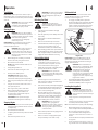
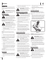
WARNING: This symbol points out important safety instructions which, if not followed, could endanger the personal safety and/or property of
yourself and others. Read and follow all instructions in this manual before attempting to operate this machine. Failure to comply with these instructions
may result in personal injury.
When you see this symbol. HEED ITS WARNING!
CALIFORNIA PROPOSITION 65
WARNING: Engine Exhaust, some of its constituents, and certain vehicle components contain or emit chemicals known to State of California to
cause cancer and birth defects or other reproductive harm.
WARNING: Battery posts, terminals, and related accessories contain lead and lead compounds, chemicals known to
the State of California to cause cancer and reproductive harm. Wash hands after handling.
DANGER: This machine was built to be operated according to the rules for safe operation in this manual. As with any type of power equipment,
carelessness or error on the part of the operator can result in serious injury. Failure to observe the following safety instructions could result in serious
injury or death.
27. Do not change engine governor setting or over
speed the engine. The governor is set at the
factory for safe operating speed.
28. Assure neutral safety interlock switch is
adjusted correctly so engine cannot be started
unless shift lever is in the neutral position.
29. Do not touch engine or muffler while engine is
running or within 30 minutes after it is stopped.
They will be hot and can cause a burn.
30. Always inspect your vehicle each time you use
it to make sure it is in safe operating condition.
Always follow the inspection and maintenance
procedures and schedules described in this
manual.
31. If situations occur which are not covered in
this manual, use care and good judgement.
Contact your local service center or call toll free
1-877-282-8684 for the name of your nearest
service center.
Occupant Size and Capacity
1. Make sure operators are at least 16 years old
and have a valid driver’s license.
2. Each occupant should be able to sit with their
back against the seat, feet flat on the floor, and
hands on the steering wheel or handholds.
3. The operator should be tall enough to wear the
seat belt properly and reach all controls.
4. Passengers should also be tall enough for the
seat belt to fit properly and be able to brace
themselves, as necessary, by placing both
feet firmly on the floor while gripping the
handholds. Keep all body parts completely
inside the vehicle.
Dress Properly
1. Proper clothing can reduce the severity of
injury in the event of an accident.
2. Always wear appropriate eye protection and
protective clothing. It is also recommended
that you wear a properly fitting D.O.T. approved
helmet.
Slope Operation
Slopes are a major factor related to loss of control and
rollover accidents, which can result in severe injury
or death. If a slope is steeper than a 15° incline, do
not operate this unit on that area. Exercise extreme
caution while operating on slopes.

4 Section 2 — important Safe operation practiceS
Safety Frame (OPS)
1. Your vehicle is equipped with a operator
protective structure (OPS) which must be
maintained in a fully functional condition. Use
care when driving through doorways or spaces
with a low overhead.
a. Never modify the OPS in any way.
b. Never attempt to straighten or reweld
any part of the main frame if damaged.
Doing so may weaken the structure
and endanger your safety. Replace a
damaged OPS immediately.
c. Never secure any parts other than Cub
Cadet approved accessories on the
main frame or attach the safety frame
with anything other than the special
fasteners specified.
d. Never attach ropes, chains, or cables to
the OPS for pulling purposes.
e. Although the OPS, when used with a
properly secured seat belt, provides a
crush-protective environment in the
event of a tip-over or rollover, never
take unnecessary risks.
Children
1. Tragic accidents can occur if the operator is
not alert to the presence of children. Children
are often attracted to the vehicle. They do not
understand the dangers. Never assume that
children will remain where you last saw them.
Avoid run over accidents.
a. Keep children out of the immediate
area of the vehicle and in watchful care
of a responsible adult other than the
operator.
b. Be alert and turn the vehicle off if a
child enters the area.
c. Before and while backing, look behind
and down for small children.
d. Never carry small children, they may fall
off and be seriously injured or interfere
with safe vehicle operation.
e. Use extreme care while approaching
blind corners, doorways, shrubs, trees
or other objects that may block your
vision of a child who may run into the
path of the vehicle.
f. Remove key when vehicle is unattended
to prevent unauthorized operation.
2. Never allow children under 16 years old to
operate this vehicle. Children 16 years old and
over should read and understand the operation
instructions and safety rules in this manual and
should be trained and supervised by a parent
and has obtained a state-issued motor vehicle
driver’s license.
3. Do not let children ride in the cargo bed, in
the driver’s or passenger’s lap or anywhere
other than the passenger seat. Never give small
children a ride; not even in the passenger seat.
The passenger seat belts, handholds and seat
height are not designed to accomodate the
safe transport of small children.
Service
Safe Handling Of Fuel:
1. To avoid personal injury or property damage, use
extreme care in handling fuel. Fuel is extremely
flammable and the vapors are explosive. Serious
personal injury can occur when fuel is spilled on
yourself or your clothes which can ignite. Wash
your skin and change clothes immediately.
a. Use only an approved fuel container.
b. Never fill containers in the cargo bed
inside a vehicle or on a truck or trailer
bed with a plastic liner. Always place
containers on the ground away from
your vehicle before filling.
c. When practical, remove gas-powered
equipment from the truck or trailer and
refuel it on the ground. If this is not
possible, then refuel such equipment
on a trailer with a portable container,
rather than from a fuel dispenser
nozzle.
d. Keep the nozzle in contact with the rim
of the fuel tank or container opening at
all times until fueling is complete. Do
not use a nozzle lock-open device.
e. Extinguish all cigarettes, cigars, pipes
and other sources of ignition.
f. Never fuel vehicle indoors.
g. Never remove gas cap or add fuel while
the engine is hot or running. Allow
engine to cool at least five minutes
before refueling.
h. Never over fill fuel tank. Fill tank to no
more than ½ inch below bottom of filler
neck to allow space for fuel expansion.
i. Replace fuel cap and tighten securely.
j. If fuel is spilled, wipe it off the
equipment. Push vehicle away from
spilled fuel. Wait 5 minutes before
starting the engine.
k. To reduce fire hazards, keep engine
compartment and exhaust system free
of grass, leaves, or other debris build-
up. Clean up oil or fuel spillage and
remove any fuel soaked debris.
l. Never store the vehicle or fuel container
inside where there is an open flame,
spark or pilot light as on a water heater,
space heater, furnace, clothes dryer or
other gas appliances.
m. Avoid injury from explosion or fire.
DO NOT carry fuel or other flammable
liquids in vehicle or cargo bed.
General Service
1. Never run an engine indoors or in a poorly
ventilated area. Engine exhaust contains
carbon monoxide, an odorless and deadly gas.
2. Before cleaning, repairing, or inspecting, make
certain all moving parts have stopped. Remove
the ignition key to prevent unintended starting.
3. Check brake and parking brake operation
frequently as it is subjected to wear during
normal operation. Adjust and service as
required.
4. Keep all nuts, bolts, and screws tight to be sure
the equipment is in safe working condition.
5. Never tamper with the safety interlock system
or other safety devices. Check their proper
operation regularly.
6. Never attempt to make adjustments or repairs
to the machine while the engine is running.
7. Do not change the engine governor settings or
over-speed the engine. The governor controls
the maximum safe operating speed of the
engine.
8. Maintain or replace safety and instruction
labels, as necessary.
9. According to the Consumer Products Safety
Commission (CPSC) and the U.S. Environmental
Protection Agency (EPA), units in this product
category have an Average Useful Life of seven
(7) years, or approximately 400 hours of
operation. To extend the life of your unit, and
specifically after (7) years of ownership or at
400 hours of operation, have the unit inspected
annually by an authorized service dealer to
ensure that all mechanical and safety systems
are working properly and not worn excessively.
Failure to do so can result in accidents, injuries
or death. See Section 5 of this Operators
Manual for Maintenance and Service schedules.
10. Observe proper disposal laws and regulations
for gas, oil, etc. to protect the environment.
Do:
1. Travel straight up and down slopes, not across.
Exercise extreme caution when changing
direction on slopes.
2. Travel slowly while on a slope. Always keep the
speed limited when going down slopes to take
advantage of the engine braking action.
3. Keep all movement on the slopes slow and
gradual. Avoid starting or stopping on a slope.
4. Avoid slopes with slippery, loose, or bumpy
surfaces as they are especially hazardous.
5. Use extra care while carrying cargo. It may
affect the stability of the vehicle. Spread the
load evenly and secure to prevent movement.
Do Not:
1. Do not travel near drop-offs, ditches or
embankments. The vehicle could suddenly turn
over if a wheel goes over the edge of a cliff,
ditch, or if an edge caves in.
2. Do not stop or start suddenly when going
uphill or downhill. Be especially cautious when
changing direction on slopes.
3. Do not turn sideways to the hill. The vehicle
may roll over. If you must turn, go slow and do
so carefully and gradually.
4. Do not carry cargo or tow loads on steep slopes.
Towing
1. Always use an approved hitch and hitch point
provided on the utility vehicle.
2. Do not tow more than 500 lbs. rolling weight
(i.e. trailer plus cargo).
3. Never load more than 85 lbs. tongue weight on
tow bracket provided.
4. Go slow and use extra care when towing a
trailer. Allow for increased braking distance.
Load trailer properly.
5. Do not tow heavy loads on slopes greater than
5° incline. When going downhill or turning, the
extra weight tends to push the tow vehicle and
may cause you to lose control (i.e. braking and
steering ability are reduced, towed equipment
may jack-knife and cause utility vehicle to
overturn).
Cargo Bed Loading/Operation
1. Do not exceed vehicle’s Total Payload Capacity
rating of 850 lbs. This includes operator,
passenger, accessories, attachments, tongue
weight and cargo.
2. Do not exceed 350 lbs. load in cargo bed.
3. Spread load evenly and secure to prevent
movement.
4. Do not load above height of cargo bed.
Load could shift forward and injure driver or
passenger.
5. Avoid loads which exceed the physical
dimensions of cargo bed.
6. Go slow. Heavy loads will affect steering,
braking, stability, and overall handling of the
vehicle. Limit loads to those that can be safely
controlled.
7. Avoid sudden starts, stops, and turns which
could cause load to shift.
Cargo Bed Lift
1. Stop vehicle on level ground and set Parking
Brake before raising cargo bed.
2. Empty heavy cargo by hand.
3. Do not operate vehicle with cargo bed in raised
position.
4. Do not operate vehicle with cargo bed
unlatched. Always latch upon manually
lowering cargo bed.

5Section 2 — important Safe operation practiceS
11. Prior to disposal, determine the proper
method to dispose of waste from your local
Environmental Protection Agency. Recycling
centers are established to properly dispose of
materials in an environmentally safe fashion.
12. Use proper containers when draining fluids.
Do not use food or beverage containers that
may mislead someone into drinking from them.
Properly dispose of the containers immediately
following the draining of fluids.
13. DO NOT pour oil or other fluids into the
ground, down a drain or into a stream,
pond, lake or other body of water. Observe
Environmental Protection Agency regulations
when disposing of oil, fuel, coolant, brake fluid,
filters, batteries, tires and other harmful waste.
14. We do not recommend the use of a pressure
washer to clean your unit. It may cause damage
to electrical components; pulleys; bearings;
or the engine. The use of high pressure and
water will result in shortened life and reduce
serviceability.
Do not modify engine
To avoid serious injury or death, do not modify engine
in any way. Tampering with the governor setting can
lead to a runaway engine and cause it to operate at
unsafe speeds. Never tamper with factory setting of
engine governor.
Notice Regarding Emissions
Gasoline powered products may be equipped with
the following emission control systems: Engine
Modification (EM), Oxidizing Catalyst (OC), Oxygen
Sensor (O2S), Multi-port Fuel Injection (MFI), Electronic
Control Module (ECM), Secondary Air Injection (SAI)
and Three Way Catalyst (TWC). When required, models
are equipped with low permeation fuel lines and fuel
tanks for evaporative emission control. Please contact
Customer Support for information regarding the
evaporative emission control configuration for your
model.
Spark Arrestor
WARNING: This unit is equipped with
an internal combustion engine, muffler
and spark arrestor. Do not use on or
near any unimproved forest-covered,
brush-covered or grass-covered land
without the proper muffler and spark
arrestor in place.
The spark arrestor should be
maintained in effective working order by the operator.
In the State of California the above is required by law
(Section 4442 of the California Public Resources Code).
Other states may have similar laws. Federal laws apply
on federal lands.
A replacement spark arrestor for the muffler is
available through your nearest authorized engine
service dealer or contact the service department, P.O.
Box 361131 Cleveland, Ohio 44136-0019.
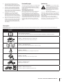
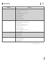
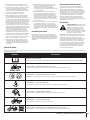
Safety Symbols
This page depicts and describes safety symbols that may appear on this product. Read, understand, and follow all instructions on the machine before attempting to
assemble and operate.
Symbol Description
READ THE OPERATOR’S MANUAL(S)
Read, understand, and follow all instructions in the manual(s) before attempting to assemble and operate.
WARNING — DRIVER MUST BE AT LEAST 16 YEARS-OLD
Young drivers may not be able to safely control vehicle.
WARNING — IMPAIRED OPERATION
Never operate the vehicle under the influence of alcohol or drugs.
WARNING— SEAT BELTS
Always wear the seat belt when operating the utility vehicle.
WARNING— ROLL OVER
Falling off or rollover may cause serious injury or death.
WARNING— ONE RIDER PER SEAT
Only one person in each seat.
WARNING— RIDERS MUST BE IN SEATS
No riders in cargo bed or anywhere other than seats.

6 Section 2 — important Safe operation practiceS
WARNING: Your Responsibility—Restrict the use of this power machine to persons who read, understand and follow the warnings and
instructions in this manual and on the machine.
SAVE THESE INSTRUCTIONS!
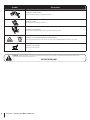
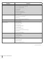
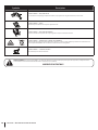
Symbol Description
WARNING — RIDERS FALLING
Riders can fall off and be seriously injured or killed.
MAX 15º
WARNING— SLOPES
Do not operate on slopes greater than 15°.
WARNING— CRUSH HAZARD
Keep hands and other body parts safely away when lowering cargo bed.
WARNING — GAS CONTAINER OR OTHER FLAMMABLE LIQUIDS
Avoid injury from explosion or fire. Do not carry fuel or other flammable liquids in vehicle or cargo bed.
WARNING— HOT SURFACE
Hot Surface - Do not touch.

Controls & Features
3
7
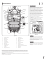
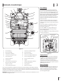
Read this operator’s manual, safety symbols, and operating instructions on the vehicle before operating.
Compare the illustrations in this manual with your unit to familiarize yourself with the location of various
controls and adjustments. Reference to the right or left hand side of unit is observed from the operating
position. Save this manual for future reference.
IMPORTANT: Refer to the Engine Operator’s Manual before operating this vehicle to familiarize yourself with
the engine controls and adjustments.
A Instrument Cluster
B Choke Knob
C Ignition Switch
D Hood Latch
E Steering Wheel
F Accelerator Pedal
G Brake Pedal
H Parking Brake Lever
I Seat Belt Latch
J Seat Belts
K Cargo Bed Latch Lever
L Tailgate Latch
M Bed Tie-Down Ring
N Fuel Tank
O Dierential Lock Lever
P Shift Lever
Q 12 Volt Power Outlet
R Handhold
S Auxillary Switch Panel
T Operator Protective Structure (OPS)
U Cup Holders
V Hitch Plate
Figure 3-1
A
B
C
D
E
F
G
H
I
J
K
L
M
L
N
I
J
O
P
Q
D
R
R
S
T
U
V
OO
OO
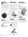
Instrument Cluster
The instrument cluster is located in the middle of the
dash panel. It contains multiple displays, indicator
lights and mode buttons. It displays Fuel Level,
Vehicle Speed (KM/H, MPH), Gear Selection (F, N or R)
and the Odometer reading when the key is turned to
the “ON” position. In addition, the Seat Belt Warning
Indicator will flash for 8 seconds to remind the
operator and passenger to fasten their seat belt.
The Low Voltage Indicator will illuminate when your
battery reaches 11.6 volts. The other indicator lights
will not illuminate until that function is used.
The Fuel Level is divided into 5 segments and flashes
at the lowest increment. See Figure 3-2.
The MODE button switch changes the display from
distance driven (KM/MILE) to time of use (Hrs.).
The KM/MILE button switch changes the display
from KM/H to MPH. See Figure 3-2.
Parking Brake
Indicator
Low Voltage Indicator
High Beam Indicator
Gear Position
Indicator
Seat Belt Warning
Indicator
Figure 3-2
Hour Meter
The hour meter is located in the instrument cluster.
To display the hour meter, press the mode button
switch to change the display from distance driven to
time of use. It records the elapsed time when the key
is in the Run position. See Figure 3-2.
Choke Knob
The choke knob is located to the right of the ignition
switch on the dash. The choke is used when starting
a cold engine. To set, pull out to engage, push in to
disengage.

8 Section 3— controlS and FeatureS
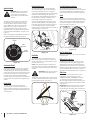
Parking Brake Lever
The parking brake lever is located between the
driver and passenger’s seat. It holds the parking
brake in the engaged position, once engaged.
To engage the parking brake, pull up on the parking
brake lever, and the parking brake indicator on
the instrument cluster will illuminate and the gear
position indicator will flash to remind you the
parking brake is engaged. See Figure 3-2.
To release the parking brake, push down on the
brake pedal, pull slightly up on the parking brake
lever while depressing button, and move the lever
to the disengaged position. The parking brake
indicator will go out and the gear position indicator
will stop flashing. See Figure 3-4.
Depress
Disengaged
Engaged
Figure 3-4
Seat Belts
The seat belts are located on the outside of the
driver and passenger seats. Pull across your chest
and lap and secure it to the seat belt latch located
near the center console.
NOTE: Seat belt warning indicator will flash for 8
seconds once the key is turned to the ON position to
remind the operator and passenger to fasten their
seat belt.
WARNING: Always wear the seat belt
when operating the utility vehicle.
The position of the lap belt portion of the seat belt
should be positioned for both the operator and the
passenger before driving. See Figure 3-5.
Figure 3-5
Seat Belt Warning Indicator
The seat belt warning indicator located in the
instrument cluster will flash for 8 seconds once the key
is turned to the ON position to remind the operator
and passenger to fasten their seat belt. See Figure 3-2.
Seats
The seats can be adjusted to either the forward or
rearward position by removing the (4) bolts securing
them to the seat pan and reinstalling them into the
seat in the other (4) holes of the seat pan. Tighten
bolts to 170 in-lb. See Figure 3-6.
Figure 3-6
Bed Tie-Down Rings
The bed tie-down rings can be used to secure items
for transporting.
Differential Lock Lever
The differential lock lever is located in the center
console between the seats. When engaged, the
differential lever locks the rear differential, giving
equal power to both rear wheels. See Figure 3-7. In
addition, when the differential lock lever is in the ON
position, the Differential Lock Indicator located in
the instrument cluster will illuminate. See Figure 3-2.
Shift Lever
The shift lever is located in the center console
between the seats and has three positions
(FORWARD, NEUTRAL, and REVERSE). See Figure
3-7. The brake pedal must be fully depressed
when moving the shift lever. One of the three gear
positions will be displayed in the instrument cluster.
See Figure 3-2.
IMPORTANT: Never force the shift lever or attempt
to shift while in motion. Doing so may result in
serious damage to the utility vehicle’s transmission.
Forward
Reverse
Neutral
OFF
ON
Shift Lever
Figure 3-7
Ignition Switch
WARNING: Never leave a running
machine unattended. Always set
parking brake, stop engine and
remove key to prevent unintended
starting.
The ignition switch is located to the right of the
steering wheel. To start the engine, insert the
key into the ignition switch and turn clockwise
to the START position. Release the key into the
RUN position once engine has started. To use
the highbeam feature, turn the key back to the
highbeam position. The high beam indicator in the
instrument cluster will illuminate. See Figure 3-2 &
Figure 3-3.
Refer to Starting Engine in the Operation Section of
this manual for detailed starting instructions.
High Beam
Position
RUN
Position
START
Position
Figure 3-3
Accelerator Pedal
The accelerator pedal is located to the right of the
brake pedal, beneath the dash panel. See Figure
3-1. Depressing the accelerator pedal will move the
vehicle in the direction selected on the shift lever. As
the pedal is slowly depressed, speed will continue
to increase to the desired speed. Releasing the
pedal will reduce the speed, but will not completely
stop the vehicle. The brake must be applied to stop
vehicle.
Brake Pedal
The brake pedal is located to the left of the
accelerator pedal, beneath the dash panel. See
Figure 3-1. Remove foot from accelerator pedal and
apply pressure to the brake pedal until vehicle slows
down and stops.

9Section 3 — controlS and FeatureS
12V Power Outlet
The 12V power outlet is located on the right side
of the dash panel. It is used for the convenience of
plugging in accessories that require a power source
with a maximum load of 5A at 12V.
Auxiliary Switch Panel
The auxiliary switch panel is located on the right
hand side of the dash panel above the handhold.
When adding accessories requiring switches, use
this area of the dash panel to install the desired
switches.
Occupant Protective Structure (OPS)
This utility vehicle is equipped with an Occupant
Protection Structure (OPS) and seat belts. When
used together they are effective in reducing
crushing injuries to the operator and passenger in
the event of an accidental rollover or tip-over. The
safety provided by the OPS is minimized if the seat
belt is not properly adjusted AND buckled.
WARNING: Always wear the seat belt
when operating the utility vehicle.
Use the following guidelines when using a utility
vehicle equipped with OPS:
1. Be aware of overhead clearances in the area
of operation. Check for clearance of door (or
gate) openings and other overhead objects
such as utility lines and tree branches.
Overhead objects could catch the OPS and
upset the utility vehicle.
2. Do not modify the OPS by drilling holes for, or
welding accessories to the structure.
3. Do not use the OPS to pull objects with the
utility vehicle. Use ONLY the utility vehicle
hitch for pulling.
4. Do not operate the utility vehicle without the
OPS and do not remove the OPS.
5. In the event of an accident, have the OPS
carefully inspected and, if necessary, replaced
by your Cub Cadet dealer. Do not attempt to
repair the OPS.
Cup Holders
The cup holders are located on top of the dash panel
on both the left and right hand sides.
WARNING: Never operate this vehicle
while under the influence of alcohol or
drugs. Doing so can result in serious
personal injury or death.
Cargo Bed
The cargo bed maximum capacity is 350lbs. The
cargo bed may be tilted for dumping loads. Push
forward on the cargo bed latch lever to unlock the
bed and manually lift the cargo bed. See Figure 3-1.
NOTE: Access to the engine is achieved by raising
the cargo bed.
IMPORTANT: Do not exceed the vehicle’s Total
PayLoad Capacity of 850 lb (385 kg), which includes
driver, passenger, accessories, tongue load and
cargo. Do not exceed 350 lb (158 kg) in the cargo
bed.

Operation
4
10
Tire Inflation
IMPORTANT: Inflation pressure in all tires is 14 psi.
Overinflating above recommended tire pressure can
reduce the life of the tire. Check tire pressures before
each use.
WARNING: Excessive pressure (above
14 psi) may cause the tire/rim
assembly to burst with sufficient force
to cause severe injury or death.
Starting Engine
WARNING: This is an off-road utility
vehicle and it should not be operated
on public highways. Know and comply
with all laws and regulations
governing the use of off-highway
vehicles in your area.
IMPORTANT: Before starting the engine, read this
manual and the Engine manual thoroughly to
understand all instructions.
WARNING: Do not run an engine in
an enclosed area. Engine exhaust
contains carbon monoxide, which is
very poisonous and can cause death.
Move the vehicle outside or to a well
ventilated area.
1. While sitting in the seat with your seat belt
fastened, insert key into ignition switch.
2. Move shift lever into Neutral.
NOTE: Engine will not start if the shift lever is
not in Neutral.
3. Verify parking brake is set.
4. Pull out the choke knob if engine is cold.
5. Turn key to the START position.
IMPORTANT: DO NOT run the starter
continuously for more than 5 seconds,
otherwise the battery may discharge quickly.
6. Release key to the RUN position when engine
starts.
7. If engine does not start, wait a few seconds
and repeat steps 5 & 6.
8. After engine starts, push in choke knob.
9. Release parking brake while your foot is
on the brake pedal, place shift lever in
the desired gear, release brake and press
accelerator pedal slowly.
IMPORTANT: Do not operate the engine
under full load until engine has warmed up.
Stopping Engine
1. To stop utility vehicle, release accelerator pedal
and depress brake pedal until vehicle comes to
a complete stop.
2. Move shifter back into Neutral.
3. Set parking brake and turn key switch to STOP
position.
4. Remove the key when not in use.
WARNING: The vehicle may roll if the
parking brake is not engaged. Always
set the parking brake, especially on
slopes.
Refueling Fuel Tank
WARNING: Avoid injury from
explosion or fire. Do not carry fuel or
other flammable liquids in vehicle or
cargo bed.
1. Stop vehicle on a level surface and apply
parking brake.
2. Turn the ignition key to the STOP position and
remove key.
3. Allow engine to cool for five minutes before
adding fuel.
4. Clean area around fuel cap and remove.
5. Fill tank with fresh, unleaded, regular grade
fuel only to bottom of filler neck. Use a
minimum of 87 Octane (10% Ethanol Max.).
6. After refueling, push the fuel cap downward on
the fuel tank fill neck and turn clockwise until it
clicks to tighten. Always re-install the fuel cap
tightly onto the fuel tank after removing.
Driving Utility Vehicle
1. Adjust the operator’s seat to the most
comfortable position that allows you to
operate all controls and pedals. See Seats
section in Controls & Features, page 8.
2. Adjust the seat belt to fit comfortably around
your lap, then buckle the seat belt.
WARNING: Do not operate the
vehicle without the OPS in place and
the seat belt fastened securely around
your waist and chest.
3. Start the engine as instructed earlier and
make sure the front wheels are turned to the
desired direction of travel.
4. Push down on brake pedal and pull slightly up
on the parking brake lever while depressing
the lock button and then slowly lower the
lever to release parking brake.
5. Move the shift lever in the center console
to the desired setting. To avoid damaging
transmission, depress brake pedal fully and
make sure vehicle is completely stopped
before shifting into Forward, or Reverse.
WARNING: Do not stop or start
suddenly when going uphill or
downhill. Be cautious when changing
direction on slopes. Apply brakes
when going down slopes to maintain
control of vehicle.
6. Release brake pedal and slowly apply pressure
to the accelerator pedal.
7. Release accelerator and apply brake pedal
evenly and firmly to slow down or stop.
Differential Lock
The differential lock lever is located in the center
console between the seats. See Controls and
Features section and Figure 3-1.
1. To engage; stop utility vehicle, place into
Neutral, and pull the lever upward into the ON
position. The differential will then lock and
remain so until it is disengaged, giving equal
power to both rear wheels. See Figure 4-1.
Forward
Reverse
Neutral
OFF
ON
Shift Lever
Figure 4-1
IMPORTANT: Engage the differential as the last
option when stuck in mud or similar situation or
when the left and right side wheels are turning at
slightly different speeds.
WARNING: To avoid transmission
damage, injury, or turf damage, drive
slow when operating utility vehicle
with differential lock engaged as
steering response is noticeably
reduced. Also, do not drive the utility
vehicle with the differential lock
engaged on concrete, asphalt or any
high traction surfaces.
2. To disengage the differential lock; stop the utility
vehicle, place in Neutral, and push the lever
downward to the OFF position. See Figure 4-1.
Loading the Cargo Bed
WARNING: The utility vehicle may
become unstable if the cargo bed is
loaded incorrectly. Avoid loose and
unsecured loads or uneven loading of
material.
1. Verify cargo bed is securely latched before
loading.
2. Securely anchor all loads in cargo bed and do
not load beyond maximum capacity.
Note: The maximum box capacity is 350 lb (158 kg).
3. When loading objects into cargo bed, be sure
load is securely anchored and evenly distributed.
4. Do not load above height of cargo bed.
Load could shift forward striking driver or
passenger or cause driver to lose control of
vehicle.
5. Avoid loads which exceed physical dimensions
of cargo bed.
6. Avoid concentrated loads at rear or sides of
cargo bed. Be sure load is distributed evenly.

11Section 4 — operation
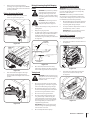
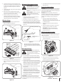
Raising & Lowering Cargo Bed (Dumping
Loads)
WARNING: To prevent the possibility
of bodily injury from unintentional
lowering of the cargo bed, be sure
vehicle is on a level and stable surface
and parking brake is set before raising
cargo bed.
WARNING: A loaded cargo bed can
be very heavy. Do not attempt to
dump a heavily loaded cargo bed.
1. Park the vehicle safely on level ground and set
parking brake.
2. Empty heavy cargo by hand.
3. For light loads, unlatch cargo bed by pushing
forward on the cargo bed latch lever. While
holding the latch lever forward with one
hand, lift the cargo bed with your other hand.
See Figure 4-5.
Cargo Bed
Latch Lever
Lift Up Cargo Bed
From Here
Figure 4-5
4. Once unloaded, lower bed and securely
latch before operating unit. Do not drive the
vehicle with cargo bed in the raised position.
Towing Loads
WARNING: To help prevent personal
injury due to loss of control or tipping,
always tow a load slow enough to
maintain control.
1. Do not tow a load that exceeds 500 lb (226
kg) rolling weight (i.e. trailer plus cargo) and
never exceed 85 lb (38 kg) tongue weight.
2. Go slow when towing a heavy load. Allow
for increased braking distance. Tow load at a
speed slow enough to maintain control.
3. Do not tow on slopes greater than 5°.
4. Be cautious when towing downhill, even
on a gradual slope or when turning. The
extra weight tends to push the tow vehicle
and may cause you to lose control (braking
and steering ability are reduced; towed
equipment may jack-knife).
IMPORTANT: Extreme angles such as high
railroad crossings can place high bending
loads on hitch connection.
5. Do not modify the hitch in any way.
Transporting the Utility Vehicle
IMPORTANT: Never tow the utility vehicle.
Transmission damage will occur if the utility vehicle
is towed. Haul the utility vehicle on a heavy-duty
trailer or on a full-size truck.
CAUTION: Do not trailer your machine with the
soft cab, hard roof or windshields installed, doing
so may result in damage of your enclosure. It is not
recommended, and will void any warranty.
1. Once the utility vehicle is loaded onto the trailer
or truck, leave shift lever in Forward or Reverse.
2. Set parking brake during transport.
3. Securely restrain the utility vehicle to trailer or
truck with straps, chains, or cables.
IMPORTANT: Do not use the OPS to restrain
the utility vehicle while transporting.
Storage Box (if equipped)
There is an optional storage box located under the
hood. To gain access, follow these steps below:
1. Unhook the hood latches and lower the hood.
See Figure 4-6.
Figure 4-6
2. Unhook the two rubber straps holding the
top cover on and remove the top cover.
See Figure 4-7.
Figure 4-7
7. Reduce load and ground speed when
operating over rough or hilly terrain. DO NOT
overload vehicle. Limit loads to those that can
be safely controlled.
Raising & Lowering the Tailgate
1. Unlatch the tailgate from cargo bed and
lower. See Figure 4-2 & Figure 4-3.
2
1
Figure 4-2
Figure 4-3
2. Raise and relatch the tailgate to the cargo
bed. See Figure 4-3 & Figure 4-4. Do not
drive the vehicle with tailgate in the lowered
position.
1
2
Figure 4-4

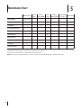
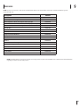
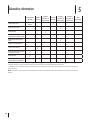
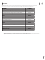
Maintenance Chart
5
12
Before Each Use
First 10
Hours
Every 20
Hours/2 Months
Every 50
Hours
Every 100
Hours or Yearly
Every 500 Hours
or 2 Years
Service Dates
Change Air Filter^
Inspect/Clean
P
Inspect Ball Joints
P
Inspect Brakes
P
Inspect/Clean CVT Air Filter
P
Inspect Front and Rear Shocks
P
Lubricate A-Arms †
P
Tighten Lug Nuts
P
Inspect OPS and Seat Belts
P
Inspect Tires
P
Change Transaxle Oil
P
^ Change more frequently if unit is operated in extremely dusty conditions.
† Lubricate after each use if unit is run through water deeper than axle.
NOTE: For information regarding engine service, see the separate Engine Owner’s Manual included with your unit.

Maintenance & Service
6
13
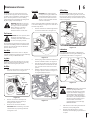
Engine Oil
WARNING: If the engine has been
recently run, the engine, muffler and
surrounding metal surfaces may be
hot and can cause burns to the skin.
Allow to cool for 30 minutes. Exercise
caution to avoid burns.
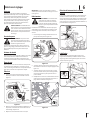
Refer to your Engine Owner’s Manual for how often
to check and change your engine oil. To drain the oil
follow the steps below:
1. Place the oil drain hose down through the hole
closest to the oil drain hose. See Figure 6-2.
Figure 6-2
2. Turn the plug counterclockwise and allow oil to
drain into a suitable container. See Figure 6-2.
3. Turn the plug clockwise, wipe any residue oil
from the oil drain hose and take the oil drain
hose out of the hole to return to its normal
position.
4. Refill the engine with new oil as instructed in
the engine operator’s manual. See Figure 6-3
for engine fill/dipstick location.
Engine
Fill/Dipstick
Figure 6-3
Cleaning
The body panels can scratch easily. Do not use
car wax on the body panels. The use of standard
car wash soap is acceptable for cleaning the body
panels. Avoid any abrasive cleaner or rubbing
compounds for these will damage the body panels.
Dry thoroughly to avoid water spots.
WARNING: DO NOT use a pressure
washer. Damage may occur if direct
hose spray comes in contact with
intake openings, or any other
electrical components, i.e. at
instrument cluster or under dash.
Tire Pressure
WARNING: Excessive pressure (above
14 psi) may cause the tire/rim
assembly to burst with sufficient force
to cause severe injury or death.
The recommended operating tire pressure is 14 psi
for all tires. Overinflating above recommended tire
pressure can reduce the life of the tire. Check tire
pressures before each use.
Seat Belts
Check proper function before each use. Replace
seat belt assembly if any damage is found. If damage
is noted, contact your Cub Cadet dealer.
Lug Nuts
Check torque of lug nuts after first 10 hours of use.
Tighten lug nuts in a diagonal pattern. Torque lug
nuts to 65-75 lb-ft using a torque wrench.
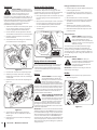
Air Filter
1. Pull up on latch and turn counter-clockwise to
release air cleaner cover. See Figure 6-1.
Element
Latch
Cover
Cap
Figure 6-1
2. Remove cover. Remove and inspect air
cleaner element. If excessively dirty or
damaged, replace element.
3. Reattach cover and secure with latch.
IMPORTANT: When reattaching cover, make
certain that the cap is pointing downward.
See Figure 6-1 inset.
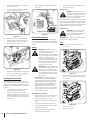
CVT Air Filter
To access the CVT air filter element, remove the
CVT filter houing by removing the two screws and
the hose clamp. Inspect and clean the CVT air filter
element with mild soap and water. Allow to dry and
install. See Figure 6-4.
Element
Housing
Screw
Hose Clamp
Figure 6-4
Lubrication
Use a grease-gun filled with No. 2 Multipurpose
Lithium Base Grease for the eight zerk fittings (four
on each side) on the A-Arms. See Figure 6-5.
Figure 6-5
Transaxle
WARNING: The fluid for your transaxle
has been specially formulated to
ensure the safe and proper operation
of your vehicle. When changing your
transaxle fluid replace it with part no.
490-000-V045 – Shell Spirax 80W-90
GL5. Failure to use Shell Spirax 80W-90
GL5 oil may result in a failure of your
transaxle which could result in
property damage or personal injury.
DO NOT substitute.
1. Park vehicle on level surface, place shift lever
in Neutral, and set parking brake.
2. Allow the unit sufficient time to cool (30
minutes) before attempting any maintenance
or repairs.

14 Section 6— Maintenance & Service
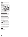
6. Install battery. Always install negative cable
last when connecting.
Charging Battery
WARNING: Charge battery in a well
ventilated area and keep away from an
open flame or pilot light as on a water
heater, space heater, furnace, clothes
dryer or other gas appliances.
If the vehicle has not been put into use for an extended
period of time, charge the battery with an automotive
type 12V charger for a minimum of one hour at six amps.
The Low Voltage Indicator on the instrument cluster will
illuminate when your battery reaches 11.6 volts.
Jumping Battery
WARNING: Do not attempt to jump
start a battery. Do not smoke near
battery and wear eye protection and
gloves when handling battery.
IMPORTANT: If your battery is dead, then follow the
instructions for charging the battery.
Fuses
1. Remove hood latches and lower the hood.
See Figure 6-9.
Figure 6-9
2. Remove the Acc (accessory) electrical fuse and
replace if needed with proper rated amp fuse.
See Figure 6-10.
Acc Fuse
Figure 6-10
3. Raise and secure hood.
4. Raise the driver’s seat.
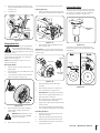
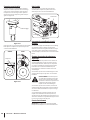
3. Once adjustment is complete, retighten the
locking nut.
Adjustment Nut
Locking Nut
Figure 6-8
Parking Brake Adjustment
If the vehicle’s rear wheels can roll with the parking
brake set, then the park brake is in need of adjustment.
See your Cub Cadet dealer to have the brake properly
adjusted.
Battery
WARNING: The battery produces a
flammable and explosive gas. Do not
smoke near battery. Wear eye
protection and gloves when handling
the battery. Do not allow direct metal
contact across battery posts or
between the positive battery post or
terminal and adjacent metal parts. The
battery is sealed and is maintenance
free. Acid levels cannot be checked
and fluid can not be added.
WARNING: California Proposition 65
Warning: Battery posts, terminals, and
related accessories contain lead and
lead compounds, chemicals known to
the State of California to cause cancer
and reproductive harm. Wash hands
after handling.
IMPORTANT: If removing the battery for any
reason, disconnect the NEGATIVE (Black)
wire from its terminal first, followed by the
POSITIVE (Red) wire. When re-installing the
battery, always connect the POSITIVE (Red)
wire to its terminal first, followed by the
NEGATIVE (Black) wire. Be certain that the
wires are connected to the correct terminals;
reversing them could cause damage to your
engine’s charging system.
Cleaning Battery and Terminals
1. Remove battery from vehicle. Always remove
negative cable first when disconnecting.
2. Wash battery with solution of four
tablespoons of baking soda to one gallon of
water.
3. Rinse the battery with plain water and dry.
4. Clean terminals and battery cable ends with
wire brush until bright.
5. Apply petroleum jelly or silicone spray to
terminals to prevent corrosion.
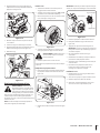
3. Locate the transaxle below the cargo bed in
the rear of the vehicle.
4. Access drain plug on underside of machine
and remove plug. See Figure 6-6.
Drain
Plug
Figure 6-6
5. Allow oil to drain into a suitable container.
6. Check O-ring on drain plug and replace if
missing, damaged or in poor condition.
7. Remove fill plug. See Figure 6-7.
Fill
Plug
Figure 6-7
8. Add 24 oz of Shell Spirax 80W-90 GL5 oil part
no. 490-000-V045 through the fill plug port.
9. Re-Install fill plug. See Figure 6-7.
Adjusting the Throttle Cable
An adjustment is provided in the throttle cable,
should such an action ever be necessary. Locate the
adjustment nut in the throttle cable running along
the right side of the unit in front of the rear tire. See
Figure 6-8.
1. Slide the rubber boot back that covers the
adjustment nut and the locking nut.
2. Loosen the locking nut and thread the
adjustment nut inward or outward in order to
maintain at minimum 1/16 of an inch play in
the cable when the pedal is in a fully released
(idle) position.

15Section 6 — Maintenance & Service
5. Remove the appropriate electrical fuse and
replace if needed with proper rated amp fuse.
See Figure 6-11.
6. Lower the seat.
System Fuse
Voltage
Regulator
Fuse
Figure 6-11
Changing Brake Pads
WARNING: Using an unstable lifting
device and vehicle supports may
result in bodily injury. Use a safe lifting
device and supports to work on raised
vehicle.
To gain access to the brake pads, remove the wheel
as described below. If less than .030” of material
remains on the pad, replace.
NOTE: Brake pads must be replaced as a set, i.e.,
right rear and left rear.
Removing the Wheels
1. Stop the vehicle on a level surface and set
parking brake.
2. Turn the ignition key to the STOP position and
remove the key.
3. Loosen but do not remove the four lug nuts
from the axle hub. See Figure 6-12.
Lug Nuts
Figure 6-12
4. Raise the front of vehicle with a safe lifting
device and place support stands under
vehicle frame.
WARNING: When lifting the rear of
the vehicle for any reason, DO NOT
engage the rear wheels.
5. Remove the four lug nuts and the wheel.
To change the brake pads, follow the steps below.
Removing Brake Pads
1. Remove mounting bolts securing caliper and
brake pads to steering knuckle. See Figure 6-13.
Bolts
Figure 6-13
2. Remove brake caliper assembly from brake
disc. See Figure 6-14.
IMPORTANT: Do not let the caliper hang from the
brake hose. Stressing the brake hose can damage it
and cause leaks.
Brake Caliper
Assembly
slide pins
brake piston
Figure 6-14
3. Remove brake pads from brake caliper
assembly.
4. Clean and lube slide pins. See Figure 6-14.
5. Press in brake piston. See Figure 6-14.
IMPORTANT: When pressing in brake piston,
take care not to damage rubber piston seal.
6. Place brake pads on slide pins.
7. Move caliper into place, making sure brake
disc is between the two brake pads.
8. Apply Loctite ® 242 to the threads of the bolts
removed earlier.
9. Secure caliper and brake pads with mounting
bolts. Torque the mounting bolts to 22-26 ft. lbs.
Reinstalling the Wheels
1. Place the wheel on the axle hub and secure
with the four lug nuts.
2. Tighten the lug nuts diagonally until snug.
3. Remove support stands and lower vehicle.
4. Finish tightening the lug nuts to 65-75 lb-ft
using a torque wrench.
Front and Rear Shocks
All four shocks are adjustable. Adjust as needed for
comfort/load level. Turn the collar at the bottom of
the shocks to one of the five positions. Adjust the
left and right side equally. See Figure 6-15.
Adjustment
Collar
Figure 6-15
See Figure 6-16. If excessive oil leakage appears,
have shocks repaired or replaced by your local Cub
Cadet dealer.
Shock
Shock
Figure 6-16

16 Section 6— Maintenance & Service
Ball Joints
See Figure 6-17. If excessive wear appears, have ball
joints or tie rod ends replaced by your local Cub
Cadet dealer.
Ball Joints
Tie Rod End
Figure 6-17
Neutral Safety Interlock Switch
Your unit is equipped with a neutral safety interlock
switch. The engine cannot be started unless the shift
lever is in the Neutral position. If the switch is out of
adjustment or needs replacement contact your Cub
Cadet dealer.
Occupant Protective Structure (OPS)
Periodically (at least every six months), visually
inspect the OPS and seat belts. It is important that
these features be inspected for damage and proper
function before each use, or daily. Contact your Cub
Cadet dealer and replace the belt assembly if any
damage is found.
If an accident has occurred which may have
damaged the OPS, have the OPS thoroughly
inspected by your Cub Cadet dealer.
WARNING: To ensure the structural
integrity of the OPS to provide
occupant protection, do not attempt
to straighten or weld the OPS. A
damaged OPS should be replaced.
If the OPS is removed for any reason, make sure the
proper hardware is used to reinstall it, and that the
recommended torque values are applied to the
fasteners.
If you are not installing new bolts when replacing
or reinstalling the OPS, apply Loctite ® 242 to the
threads of the bolts that were removed. Torque the
bolts to 50-55 ft. lbs using a torque wrench.
Drive Belt
IMPORTANT: See your Cub Cadet Dealer to have
your drive belt replaced..

Troubleshooting
7
17
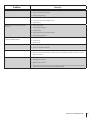
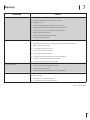
Problem Cause(s)
Engine will not start 1. Battery has low voltage.
2. Loose or corroded battery connections.
3. Fuse is blown.
4. Spark plug wire is loose or disconnected
5. Faulty spark plug or coil
6. No Fuel or improper fuel.
7. Plugged fuel filter.
8. Defective starter solenoid.
9. Open-circuit in wiring.
Engine is difficult to start 1. Engine is cold.
2. Choke not being used or adjusted properly.
3. Plugged fuel filter.
4. Carburetor not adjusted properly or dirty.
5. Engine oil viscosity too heavy.
6. Spark plug is fouled.
7. Faulty spark plug or wire.
8. Loose or corroded electrical connections.
9. Stale or improper fuel.
Engine misfires under load 1. Faulty spark plug.
2. Stale or dirty fuel.
3. Plugged fuel filter.
4. Faulty coil or wire.
Engine does not restart when warm 1. Poor quality fuel.
2. Very hot weather conditions.
3. Fuel tank vent plugged.
4. Dirt in fuel filter.
Continued on next page

18 Section 7 — troubleShooting
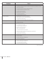
Problem Cause(s)
Engine runs unevenly 1. Loose electrical connections.
2. Choke (if equipped) or throttle cable sticking.
3. Fuel line or fuel filter plugged.
4. Stale or dirty fuel.
5. Improper fuel.
6. Air cleaner element plugged.
7. Carburetor not adjusted correctly.
8. Spark plug is fouled.
Engine overheats 1. Air cleaner element missing or plugged.
2. Carburetor air intake tube plugged.
3. Engine oil low.
4. Engine operated too long at slow engine speed.
Engine knocks 1. Stale or low octane fuel.
2. Engine overloaded.
Engine loses power 1. Engine overheating.
2. Too much oil in engine.
3. Faulty spark plug.
4. Fuel supply being restricted.
5. Fuel filter plugged.
6. Fuel line pinched or kinked.
7. Fuel pump output not adjusted to specification.
8. Improper fuel.
9. Air cleaner element plugged.
Starter does not work 1. Loose or corroded connections.
2. Low battery output.
3. Dead or Faulty battery.
4. Faulty starter.
Starter cranks slowly 1. Low battery output.
2. Dead or Faulty battery.
3. Engine oil too heavy.
4. Loose or corroded connections.
Continued on next page

19Section 7 — troubleShooting
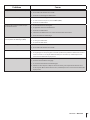
Problem Cause(s)
Entire electrical system does not work 1. Blown fuse.
2. Loose or corroded connections.
3. Dead or Faulty battery.
Dead battery 1. Shorted starter solenoid.
2. Key switch not turned to STOP position.
3. Faulty battery.
Battery light comes on when engine is
running
1. Low engine speed.
2. Faulty voltage regulator.
3. Faulty battery.
4. Faulty alternator or loose alternator belt.
5. Damaged wiring harness
Indicator lights do not come on when key
switch is in START position
1. Faulty bulb.
2. Faulty wiring.
3. Faulty sensor.
Battery will not take a charge 1. Dead battery.
2. Loose or corroded connections.
Difficult to shift 1. Idle speed too fast.
2. Gears not lined up. Tap throttle and let it return to idle. If still hard to shift, contact your nearest
Cub Cadet dealer.
Vehicle will not move 1. Shift Lever still in Neutral.
2. Parking Brake is still set.
3. Broken or cut drive belt.
4. Safely check to see if the vehicle will go in Reverse and then try to go Forward. If vehicle still will
not move forward, contact your nearest Cub Cadet dealer.

Specifications
8
20
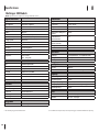
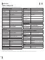
NOTE: Specifications subject to change without notice.
Engine/Electrical
Make Subaru, EX40
Type/ Cylinders 4 Cycle Gas/ 1 Cylinder
Displacement 404cc
Maximum Torque 27 N-m/19.9 ft-lb*
Ignition Magneto
Lubrication Splash w/ chain carry
Speed (No Load) 1400 rpm (idle) 4,000 rpm (fast)
Cooling System Air-Cooled
Air Cleaner Replaceable, dual element
Battery 12V 14AH 230 CCA
Alternator 12V-16A Regulated
Headlights Two, 8.4 Watt LED
Wiring Automotive - Style Fused Control System
Suspension Front - A-Arm
Rear - Swing Arm
Transmission
Type Continuously Variable
Drive Belt
Ground Speed 24 mph (max.)
Transaxle Fully Enclosed, Oil Bath
Gear Selection Forward, Neutral, Reverse
Overall Reduction Ratio Forward 13.25, Reverse 14.36
Rear Axle Housing Aluminum
Features
Dual Cup Holders Standard
Additional Storage Dash Box
Power Port 12V, Dash Mounted
Front Bumper Standard
LED headlights Standard
Dimensions
Length/ Width 98.6” x 49.0” (98.6” x 51.6” w/ roof)
Tread Center F: 41.8”/ R: 39.5”
Height (Overall) 75.2” (76.2” w/ roof)
Wheelbase 64”
Weight (Not Including Fuel
& Fluids)
940 lbs.
Ground Clearance
(Under Transaxle)
5.5”
Ground Clearance
(Under Footboard)
7.5”
Turning Radius 15.0 ft
Bed 28” L x 37” W x 12” H
Operation
Brake Type Front:Hydraulic Disc Rear:Hydraulic Drum
Parking Brake Hand Operated Mechanical Drum
Steering Rack & Pinion
Fuel System
Capacity 5 Gallons
Low Fuel Indicator Dash Mounted Indicator Gauge
Capacity
Volume - Cargo Bed 6.94 ft
3
Cargo Bed Capacity 350 lbs.
Seating - Capacity/Type 2/ Mid Back
Towing Capacity 500 lbs. (85 lbs. max. tongue weight)
Payload Capacity** 850 lbs.
Cargo Bed
Material Plastic composite
Tires
Trail Front 21” x 10” - 7” (14 psi)
Trail Rear 22” x 10” - 9” (14 psi)
* As rated by engine manufacturer.
** Includes 250 lb operator, 250 lb passenger, and maximum bed capacity.
Challenger 400 Models
La page est en cours de chargement...
La page est en cours de chargement...
La page est en cours de chargement...
La page est en cours de chargement...
La page est en cours de chargement...
La page est en cours de chargement...
La page est en cours de chargement...
La page est en cours de chargement...
La page est en cours de chargement...
La page est en cours de chargement...
La page est en cours de chargement...
La page est en cours de chargement...
La page est en cours de chargement...
La page est en cours de chargement...
La page est en cours de chargement...
La page est en cours de chargement...
La page est en cours de chargement...
La page est en cours de chargement...
La page est en cours de chargement...
La page est en cours de chargement...
La page est en cours de chargement...
La page est en cours de chargement...
La page est en cours de chargement...
La page est en cours de chargement...
La page est en cours de chargement...
La page est en cours de chargement...
La page est en cours de chargement...
La page est en cours de chargement...
-
 1
1
-
 2
2
-
 3
3
-
 4
4
-
 5
5
-
 6
6
-
 7
7
-
 8
8
-
 9
9
-
 10
10
-
 11
11
-
 12
12
-
 13
13
-
 14
14
-
 15
15
-
 16
16
-
 17
17
-
 18
18
-
 19
19
-
 20
20
-
 21
21
-
 22
22
-
 23
23
-
 24
24
-
 25
25
-
 26
26
-
 27
27
-
 28
28
-
 29
29
-
 30
30
-
 31
31
-
 32
32
-
 33
33
-
 34
34
-
 35
35
-
 36
36
-
 37
37
-
 38
38
-
 39
39
-
 40
40
-
 41
41
-
 42
42
-
 43
43
-
 44
44
-
 45
45
-
 46
46
-
 47
47
-
 48
48


Cub Cadet 37AV3AHK010 Manuel utilisateur
- Taper
- Manuel utilisateur
dans d''autres langues
- English: Cub Cadet 37AV3AHK010 User manual
Documents connexes
-
Cub Cadet 37AV3AHK010 Manuel utilisateur
-
-
-
-
Cub Cadet 37AYCCLK710 Manuel utilisateur
-
-
-
-
Autres documents
-
Bad Boy Bad Boy Ambush Le manuel du propriétaire
-
Wacker Neuson EZ26 Manuel utilisateur
-
Daewoo MUSSO SPORTS 2005 Le manuel du propriétaire
-
-
Kärcher Cadet 7 Le manuel du propriétaire
-
Subaru 2013 XV Crosstrek Le manuel du propriétaire
-
Subaru 2014 Forester Le manuel du propriétaire
-
Power Fist 8212011 Le manuel du propriétaire
-
 Cub TPM101 Mode d'emploi
-
Clarke 56265505 Manuel utilisateur
