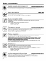
GE PNRQ15FBL00 Le manuel du propriétaire
- Taper
- Le manuel du propriétaire

www.GEAppliances.com
¢)
>
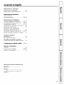
Safety Instructions
Safi:ty Instructions .............. 2
Specification Guidelines ......... g
Operating Instructions
About the RO System ......... 4, 5
Installation Instructions
Tools and Materials Required ..... 6
Before Beginning Installation . . .6, 7
Mounting System Installation ..... 8
Feed Water Supply ........... 9-12
Faucet Assembly ............ 13, 14
Battery Installation ............ 14
Filtration Drain Connection . .15, 16
Storage Tank and Startup ....... 17
Care and Cleaning
Prefitte_; Postfiher and
RO Camidge Replacement ...... 18
Sanitization .................. 19
Water Test Kit ................ 20
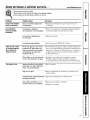
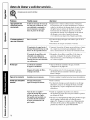
Troubleshooting Tips ...... 21, 22
Consumer Support
Consumer Support ..... Back Cover
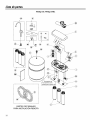
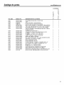
Parts List/Catalog .......... 24, 25
Warranty .................... 26
Tested and Certified by NSF International to
NSF/ANSI Standard 5& See Performance Data
Sheet for the reduction of the claims specified
on the Performance Data Sheet.
Essay_et certifi_ par NSF International
conform_ment aux normes 58 NSF/ANSI.
Consuttez ta feuille de donn_es de rendement
pour la r_duction des caract_ristiques indiqu_es
sur la feuille de donn_es de rendement,
Probado y certificado pot NSFInternational por
cumplir con el est_ndar 58.Vet la hoja de datos
de desempefio para Ia reducci6n de reclamos
especificados en la hoja de datos de desempefio,
Write the model and serial
numbers here:
Model #
Serial #
You can find _eIn on the bracket.
101019-A
PXRQ I SF
PNRQ15FBL
Osmose Inversde
Syst_me de Filtration
La section fran_aise commence a la page 27
Osmosis Inversa
Sistema de Filtraci6n
La secci6n en espafiol empieza en la pkgina 55
215Cl174P002 49-50144 11-04JR

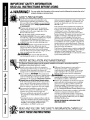
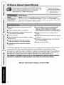
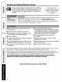
IMPORTANT SAFETYINFORMAtiON.
READALLINSTRUCtiONS BEFOREUSING.
A WARNING! ro e damagoor ersonalinju
.i SAFETYPRECAUTIONS
m Check wifll your state aim local public works
deparunent for phnnbing and _nilation codes.
You must follow these guidelines as you install fl:e
Reverse Osmosis system. Usinga qualifiedinstaller
isrecommended.
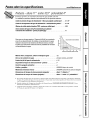
• Ifhouse water pres_sureis over the maximum
(1_'0poumts per s(p_re inclO, install a pressure
reducing valve in dm water supply line to the
Reverse Osmosis system.
• Be sure tile water supply confi,)rms with Ihe
SpecificationGuidelines.ff the water supply conditiolls
are uIlk!lowIl, COZllaCt your muIlicipal *_,ater comKomy
or your local bealfl: department ff)r a list of
coI_laminaI_tSin your area and a listof lalx)ratories
certified by your slate to analyze drinking waten
WARNING'.Before ruing dm Reverse Osmosis
system fbr the first time, tile system must be
purged. The Reverse Osmosis cartridge contains
a fbod grade preservative that tmtst be purged
from the system. The preservative will give product
water an unpleasant taste and eden
it
ltLWARNING'.Do :lot use with water that is
microbiologically unsafe or of unknown quafi/y
2
For your safe_ the information in this manual must be followed to minimize the risk of
without adequate disinfection befbre or after the
system. SDtems certified fi)r cyst reduction may
be used on disinfected water dial may contain
fiherable cysts.
This system has been tested ff)r the treatment of
water conlaiuing pentavalent aeueIfiC (alto talowI:
a_sz_s(V), As(+5) or ar_Ilate) at concentra(lOIlS
of 0.050 mg/L or less. Tiffs sysmm re&rues
peIwavalent arm:tic, but ::lay :lot remove otimr
fi_nns of arsenic. "I]lis system is to be/tsed oil water
supplies containing a detectable free dflorine
residual or on water supplies that have been
deInonstrated to contain only pentavalent arsenic.
Treatment with chloramine (combined chlorine)
is not sttitlcient to ensure complete COIlversion of
trivalent _IfiC to penlavaleI:t arseItiC. Please see
the _IfiC Facts section of the Perfbrmance Data
Sheet fbr fi_rther infi)rmafion.
This Rever_ OsInosis system contains a replaceable
treaunent Inembrane ca_ridge critical far effecfive
re&mtlon of'Ibtal Dissolved Solids. The water
should be tested pefiocrmally to verify thai tile system
is perfbmfing mtist_t(Mly.
PROPERINSTALLATIONAND MAINTENANCE
This Reverse Osmosis system must be properly installed and located in accordance with the
Installation Instructions before it is used.
• Install or store wbere it will not be expend to • If Rever_ Osmosis system is connected to a
tempeI_atures below fi'eezing or exposed to any type refrigerator icemaker, a special icemaker
of wealher. Water freezing in the system will coIllleetioI1 kit is required (RV!ZAT).Do Dot use
damage il.Do Dot attempt to treat water over 100°E copper robing ff)r file COIlIlectio[l between the
• Do :lot install Oil HOTWATER.The temperature Reverse Osmosis system aim tile refrigerator.
ofthe water supply to tile Reverse Osmosis system A [/VA_NING: Discard allum_xt pans madpackaging
UlUStbe between the lililtiinuin of 40°F and the material after il?_sPallation.Small _s remaining after
Illax'unuin of I(X)°E See tile Specification Guideline&
• Extended non-use of the Reverse Osmosissystem.
If tile sDtem has not been used fbr one week or
more, open tile RO water t_aucetand allow tile
system to drain. Close tile RO water fsucet aud
allow tile s_tem to regenerate the water supply.
• RecomIneuded installation is under the sink.
However, tile unit can be installed in a remote
location, up to 20 feet away fi_om tile sinlc
• However, adcFHional materials will be required.
See Ira,s list to obtain addifional materials
from GE.
• Locating the rank on a l_asement floor, witil the
faucet at a first floor sink may result in some loss
of flow rate laid capacily (approzdmately 20%).
Installing a second tank will iInprove tiffs
perfi_rmance. _Jl RVK1T can be umd.
tile immllallon couM be a choke ha2"ard.
• Smfitize upon installation of dm Reverse Osmosis
system and after servicing iImer parts, inchlding
replacement of prefilter, postfilter and Reverse
Osmosis carteidge. It ksimpormalt to have clean
bands wlfile haI_dling iImer parts of tile system.
See dm Sanitizingthe Reverse OsmosisSystem section.
• This Reverse Osmosis system contains a replaceable
treatment component critical fbr ef[:ccfive
reduction of total dis_solvedsolids. This product
water shall be tested periodically to verify that tim
system is performing satisfactorily. See tim About
the WaterTestKitsection.
BESURE TOFOLLOWALLAPPLICABLESTATE
AND LOCALCODES.
READAND FOLLOWTHISSAFETYINFORMATIONCAREFULLY.
SAVETHESEINSTRUCtiONS

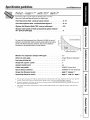
Specificationguidelines. .GE4ppliancns.oom
Product-height11" width10.5" depth4"
Ttle system Illakes a good supply of drinking waler each d_y.
How much itwill make depends primarily on these things...
Feed water pressure limilsipounds per square inch (psi) ...................... 40-120,
Feed water temperature limitsiminimum/maximum degrees F ................. 40-100
Maximum TotalDissolved Solids (TDS)ipatts per million (ppm) ................ 2000
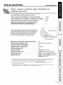
Maximum water hardness @6.9 pH recommended tooptimize membrane
lifelgrains per gallon (gpg) ................................................. 10
8
7.5
ForwatorwithhardnossgreaterthanlOgrains(at6.gpH),theuseofa _ 7
softener is recommended. Failure to install a water softener will reduce
the life of the Reverse Osmosis membrane. See chart for additional _ __
information on the possible need for a water softene_
6
'f_ _3_ENE}{ _E_MNEN#EO
,Wnot{er_eqS°u_ r
10 20 30 48 50 8[_
#l_OM#lt_ WATER_I_DN_SS (t_p_)
Maximum iron, manganese, hydrogen sulfide (ppm) ...................... <6.1
Chlorine in water supply ............................................. ZO ppm Maximum Agowab/e b
Feed water pH limits (pH) ............................................ 4-10
Storage tank capacity--gallons ....................................... 4_
Automatic shutoff control ............................................ yes
Prefilter and pnsffilter ............................................... (FQROPF)Carbon Block
Reverse Osmosis membrane ......................................... (FQROMF) Thin Film Po/yamide
Storage TankDimension (inches) ...................................... height 15"diameter 1I"
System Body Dimension (inches) ...................................... height 11" width 10.5" depth 4"
a. If house water pressure is over ] 20 psi, install a pressure reducing _-alve in the water supply line. ]i house _-ater pressure
is under 40 psi, install a Reverse Osmosis booster pump (contact your local plumbing supply company).
b. Removed (maximum ot 2.0 ppm)by the Reverse Osmosis prefilter. REGULAR MAINTENANCE IS REQUIRED.Chlorine will
destroy the Reverse Osiylosis iIlelllbr3lle.
c. Theoretical tmtk capacity. When tested according to NSF/ANSI Standard 58 at 50 psig inlet pressure, tank capacity is
2.3 gMlons.
3

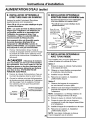
Aboutthe reverseosmosissystem.
How theReverse OsmosisSystem Works
Reverse Osmosis reduces Tolal Dissolved Solids (TDS) and organic matter from waler by diffilsing it through a special
inembrane. Tile meinbrane separates nfinerals and impurities froin tile x_rater and dmy are flushed to lhe drain. High
quality product water goes directly to tim drinking water fbucet or to 1he storage tank. The system ulakes a good supply
of drinking water each day. How lnuch it maJxes depends on the feed water supply pressure, temperature and quality.
The prefilter and postfiher are replaceable cartridges. The carbon prefiher reduces chlorine while also filtering sediments.
The postfiher reduces any other undesirable tastes and odors before you use the x_-aten
The system includes an eleclronic fiumet a._sembly*dth a prefiher and posltilter change reminden When six months have
pa._sed,a flashing blue light *rillremind you to change 1he n_,ofilters.
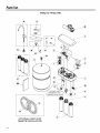
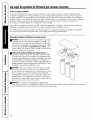
Description ofthe Reverse OsmosisSystem
_Pl_filter--Water from the cold supply pipe is directed m the
prefiher cartridge. The prefilter is a replaceable rudiment
cartridge containing activated cartxm. The prefiher re(hlces
chk)rine in the t:ce(l water because CHLORINEDESTROYSTHE
REVERSEOSMOSIS MEMBRANE Filtered, clem_, chlorine-reduced
_vtter flo_ from lhe prefilter to tim Reverse. (_mosis cartridge.
_Reverse OsmosisCartridge--The middle cartridge includes a
tightly wound, special membrane. Water is fbrced through tile
cartridge where the membrane reduces the dissolved solids and
org_aaficmatron High quality product water exits lhe Re_/erse
Osmosis caru'idge and goes Iv)the storage tank. Reject water, with
tim dissolved _)lids and organic malter, leaves the cartridge and
is discharged m the drain throu[01 1/4" tubing.
_]Postfilter--After leaving tile storage area, but before going
to the system tZaucel, product waler goes Io lhe postfilter
carlridge. The postfiher is also a replaceable sediment cartridge
that conlains activated carbon. Any remaining tastes, odors or
sedilnenls are reduced from product waler by the postfiher.
Clean, high quality drinking water flows through the robing
and to lhe systeul faucet.
_Storage Tank--The storage area holds up m 2-1/2 gallons
of product waler. A diaphragm inside lhe lank keeps water
pressurized, when Ihe tank is fifll, for fkst flow to the faucet
when drinking water is needed.
4

www.GEAppliances.com
_tCheck Valve---The check valve prevents a backward flow of product water from tile storage tank. A backward flow could
cause tile Reverse Osmosis membI_ane I(o nlplure.
_Automatic ShutoffAssembly--Tocoilserve water, tile drinking *_ater system has aI1 automatic shutofE When the smr'age milk
ha_sfilled to capacity and the drinking water t:aucet ksclosed, pressure closes the shutofE Water flow to the Reverse Osmosis
housing is shut off until drinking x_ater is used again, and pressure drops in the Reverse Osmosis system.
F_FIow CotltroI--The flow control regulates the flow of water through the Reverse (Nmosis cartridge at the required rate to
produce high quality water. The control is located in the 1/4" drain line exiting off' the manif_.)Id.
_Faucet and Electronics--The countertop [_tucel dispenses fillered drinking water when opened. It ha_sa hand-operated
lever, with wariable flow adjusunent. You can keep the f_ucet open by removing your hand fi*om the lever once water is
flowing. "Ii_comply with phunbing codes, an air gap is built into lhe f_ucet drain water connection.
The electronic faucet prox4des a six month timer to reInind you when it is time tO replace your prefilter mid postfilter.
Replace the filters when the blue light begins to flash in order to protect the RO membrane and keep tile systeIn
fimctioning properly.
5

Installation
Instructions
ReverseOsmosisFiltration System
Models PXRQ15F and PNRQ15FBL
I Questions? Call 800.GE.CARES (800.432.2737) or Visit our Website at: www.GEAppliances.com I
WARNING: Read entire manual. Failure to follow all guides and rules could cause
personal injury or property damage.
• Check with your state and/or local public works department for plumbing codes. You must
follow their guides as you install the Water Filtration system.
NOTE: Failure to comply with these installation instructions will void the product warranty, and
the installer will be responsible for any service, repair or damages caused thereby.
TOOLS AND MATERIALS
REQUIRED FOR INSTALLATION
• Electric drill and 1-1/4" Drill Bit (type as
required) if mounting is needed for faucet
• Two (2) Adjustable Wrenches
• 1/16" Drill Bit (optional for pilot holes)
• Tape Measure
• Phillips and Flat Blade Screwdrivers
• Utility Knife
• If your main water line is a rigid pipe,
you will require a compression fitting
and possibly other plumbing hardware
to complete the installation.
A _^| nTnr_Rn
J-L_/'_UIIUI_I." TO avoid damaging the
sink, consult a qualified plumber or installer
for drilling procedures. Special drill bits may
be needed for porcelain or stainless steel.
BEFORE BEGINNING INSTALLATION
Read these instructions completely
and carefully.
• IMPORTANT - Savethese
instructions for local inspector's use.
• IMPORTANT - Observea,
governing codes and ordinances.
• Note to Installer - Be sure to leave these
instructions with the Consumer.
• Note to Consumer - Keep these
instructions for future reference.
• Proper installation is the responsibility
of the installer.
• Product failure due to improper installation
is not covered under the Warranty.
• A shutoff valve must be available or added
near the installation point.
CONTENTS INCLUDED
WITH PRODUCT
• Reverse Osmosis Assembly and Tubing
• Product Literature (Owner's Manual and
Installation Instructions)
• Performance Data Sheet
• Feed Water Adapter and Supply Valve
• Faucet Assembly with Electronic Base
Monitor and Tubing
• Storage Tank
• Drain Line Adapter
6

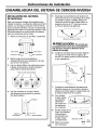
Installation Instructions
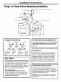
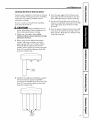
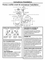
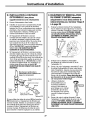
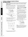
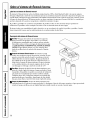
Things to Check Before Beginning Installation
RO product water faucet mounted through sink or countertop
318" drain tube (black)
T,
Disposer
Feed water ada
(yellow banded)
T
15"
j 3/8" outlet tube (blue banded)
3/8"storage
tank tube
(red banded)
TUBING/FILTER DETAIL
Prefilter Membrane Postfilter
1/4" yellow 1/4" black 3/8" red 3/8" blue
banded inlet tube to banded tube banded
from supply faucet to storage tube to
valve tank faucet
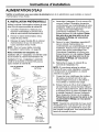
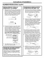
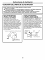
FEED WATER
The water supply to the undercounter Reverse
Osmosis system must have the qualities listed
in the specifications. Municipal water supplies
most often will have these qualities. Well
water may need conditioning--have the water
tested by a water analysis laboratory and get
their recommendations for treatment.
A ,,,A, ,T,/_R,
m-lt.r/"&U/IUl_l," For water with a
hardness greater than 10 grains (at 6.9 pH),
the use of a softener is recommended. Failure
to install a softener will reduce the life of the
Reverse Osmosis cartridge.
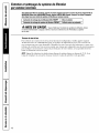
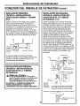
FILTRATION DRAIN CONNECTION
A suitable drain point and air gap (check your
state and/or local codes) are needed for reject
water from the Reverse Osmosis membrane
cartridge.
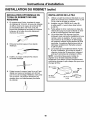
RO FAUCET
The RO product water faucet installs on the
sink or on the countertop next to the sink.
Often, it is installed in an existing sink spray
attachment hole or a hole may be drilled.
Space is required underneath for tubing to
and from the faucet, and for securing the
faucet in place. All faucet connections are
done on or above the sink or countertop.
BASEMENT INSTALLATION
If installing in a basement, leave enough
tubing in place during installation to be able
to move unit to floor for ease at servicing and
making filter/membrane changes. Additional
tubing and fittings required.
NOTE: See parts list on page 25 for optional
parts that may be required for a basement
installation.
7

Installation Instructions
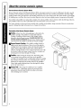
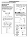
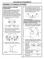
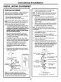
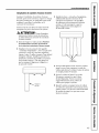
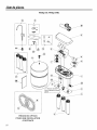
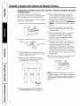
REVERSE OSMOSIS ASSEMBLY
MOUNTING SYSTEM
INSTALLATION
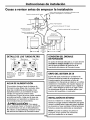
Choose a location under the sink to mount
the system. Location should be easily
accessible, with adequate clearance between
the bottom of the filter cartridges and the
floor or bottom of the cabinet for removal
of filter cartridges. Allow enough space on
either side of the system for the tubing
con nections.
1. Remove the prefilter and postfilter
cartridges.
Toremove _, U_Toremove
Prefilter "_-'_"U U_l_ • Postfilter
2. Remove the assembly cover by unlocking
the four tabs on the cover from the system.
3. Use a flat-head screwdriver to work from
left to right from the underside of the
system.
Screwdriver positioning
4. Use the icons on the bottom of the
system for screwdriver positioning.
,Tab
Screwdriver
.
Hold the Reverse Osmosis assembly up to
the wall surface where you wish to install
it. Mark location for screws. There should
be a minimum of 17 inches from the
marks to the bottom of the cabinet floor.
Screw locations
A,-, ,,, ,-,-,,-,R,
AuLI_,/-_U/IUI_I'- DO not get dirt or
debris inside the assembly area. Use only to
mark mounting hole locations.
6. Install screws to the wall, leaving a 3/16-
inch clearance between the head of the
screw and wall (drill pilot holes if needed).
8
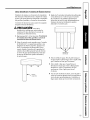
7.
Hang the Reverse Osmosis assembly on
the screws. Tighten or loosen the screws
as desired until the system is secure on
the wall.
8. To install the
cover, line up
the front
tabs on the
cover with the
openings
in the system.
9. Snap the cover
in place; the
tabs will flex,
allowing the
cover to snap
in place.
10.
J
Remove the
membrane Membran_
cartridge.
To remove

Installation Instructions
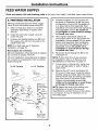
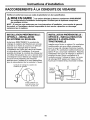
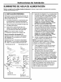
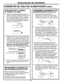
FEED WATER SUPPLY
Check and comply with local plumbing codes as you plan, then install a cold feed water supply fitting.
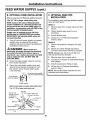
A. PREFERRED INSTALLATION
Utilizing existing kitchen sink water supply
valve (A) and removable faucet tubing (B).
1. Refer to illustration below to complete
assembly depending on supply valve
size (A).
.
3.
Close the cold water supply valve (A)
under the sink.
Unscrew the flexible tubing line (B) from
the supply valve (A) that connects to the
COLD water riser.
NOTE: For rigid pipe, see C. Optional
Installation on page 10.
Note Adapter (C) orientation:
3/8-inch installation--Rounded end of adapter
(C) connects to supply valve (A).
1/2-inch installation--Rounded end of adapter
(C) connects to coupling (D), then to existing
faucet tubing (B).
For 318" Plumbing For 1/2" Plumbing
(B) Faucet F_ _ (S} Faucet
tubing line (not _<\ _ _r ....
. tubing fine
,C} \ 'F)[_nlet v_ _) Gasket
Adapter
(A) Cold water
supply valve \
(not included) (A) Cold water
supply valve
(not included)
4. Assemble adapter (C) and coupling (D)
as shown in illustration at left, per your
configuration. Ensure that the gasket (G)
is in place before final assembly. Start
installation by hand, then finish tightening
with adjustable wrench. Be careful not
to overtighten or cross thread as damage
to threads may occur.
5. Hand tighten assembled adapter (C)
onto supply valve (A) for the proper size
installation. Be sure gasket (G) is in place
before final assembly. Start installation
by hand, then finish tightening with an
adjustable wrench. Be careful not to
overtighten or cross thread as damage
to threads may occur.
6. Reconnect faucet tubing line (B) to top
of adapter (C).
NOTE: If inlet valve (F) is to be removed
for installation, refer to E. Removal and
Reinstallation of Inlet Valve on page 11.
7. Cut wire ties on tubing coils, using care
not to damage tubes or parts if using a
utility knife.
8. Remove the 1/2" nut (I) and ferrule (H)
from end of inlet valve. Using the yellow
banded tubing provided, place the nut (I)
and ferrule (H) onto the tubing and install
onto inlet valve (F) as shown at left.
Tighten with adjustable wrench. Be
careful not to overtighten or cross thread
as damage to threads may occur.
NOTE: Inspect the ends of the tubing prior
to installation to be sure there are no
imperfections and that the end of the tubing
is cut square. It may be necessary to cut
the tubing again.
9

Installation Instructions
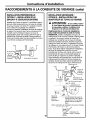
FEED WATER SUPPLY (cont,)
B. OPTIONAL HOME INSTALLATION
Where codes permit (Requires additional parts)
*For 1/2" OD or larger metal tubing only.
NOTE: Codes in the state of Massachusetts
require installation by a licensed plumber and
do not permit the use of the saddle valve. For
installation, use plumbing code 248-CMR of the
Commonwealth of Massachusetts.
Saddle valve is available through GE Parts
and Services at 1.800.626.2002, part number
WS15X10023. Self piercing saddle valves are
not recommended.
1. Turn off the cold water supply and attach
saddle valve as required by product
selection. (Be sure to follow manufacturers'
Installation Instructions).
DANGER: Many homes are
electrically grounded through the plumbing.
To protect yourself from serious injury or
fatal shock, use a battery-powered hand drill
only to make the hole. DO NOT USE AN
ELECTRIC DRILL.
2. Close the water supply valve by turning
the handle clockwise.
.
Open the main water supply valve and
several house faucets to purge air from
the system. Close faucets when water
runs smoothly.
• Snug valve into bracket
(DO NOT OVERTIGHTEN)
Some threads
should be
Rubber gasket
Optional water supply connection (using saddle valve)*
*For 1/2" OD or larger metal tubing only,
Nut (2)--not
required if holes
in clamp are
threaded "_[_.
Claml
Pre-drill
1/4" hole Seal--make sure
the seal is in place
nut
Handle
Jse to connect the tubing
C. OPTIONAL RIGID PIPE
INSTALLATION
For installation with rigid pipe between supply
valve and sink faucet.
Option 1
1. Remove pipe from supply valve and sink
faucet.
2. Obtain flexible pipe sized to your
plumbing.
3. Install flexible pipe.
4. GO back to A. Preferred Installation
section, step 4.
Option 2
1. Obtain compression fittings to fit rigid
pipe.
2. Obtain any other fittings required to
connect compression fittings to adapter.
NOTE: Adapter has 1/2-inch and 3/8-inch
internal and external threads.
3. Remove pipe from supply valve.
4. Cut pipe to fit length of assembled fittings
and adapter.
5. Install compression fitting to pipe.
6. GO back to A. Preferred Installation
section, step 4.
NOTE: Above described materials are not
included with the product.
10

Installation Instructions
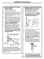
D. OPTIONAL REMOTE LOCATION
INSTALLATION
(requires additional part)
1. Turn offthe cold water supply.
.
Complying with plumbing codes, install a
fitting on the cold water pipe to adapt 1/4"
OD tubing. A typical connection is shown
in illustration below. Make sure a water
supply valve is used.
. If the RO unit is to be installed more than
6 feet from the valve, replace the yellow
banded inlet tubing with a longer length
of GE 1/4"tubing. A 33 foot length of 1/4"
tubing is available through GE Parts and
Services at 1.800.626.2002, part number
WS07X10018. DO NOT SUBSTITUTE
TUBING OF UNKNOWN QUALITY.
4. If the RO unit is to be installed more than
6 feet from the faucet, replace the blue
banded outlet tubing with a longer length
of GE 3/8" tubing. A 33 foot length is
available through GE Parts and Services at
1.800.626.2002, part number WS07X10019.
See Faucet Installation on page 13 for more
details. DO NOT SUBSTITUTE TUBING OF
UNKNOWN QUALITY.
Cold
water "J
pipe
Preferred water supply connection
(using compression fitting)
_-_ Water supply valve
/_ Insert (not included)
_/_ Ferrule
I_ RO
I14" (yellow banded) "'4_. _
tubing to inlet
If you are using copper tubing, DO NOT
connect it directly onto the RO unit. Purchase a
connector and use a short length of the yellow
banded tubing provided to make final connection
to RO. Do not use copper tubing to attach to
icemaker or faucet.
11
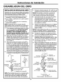
E. REMOVAL AND RE-INSTALLATION
OF INLET VALVE (requiredonly if
inlet valve needs to be removed to
complete Step 5 on page 13)
1. Remove inlet valve (F) from adapter (C)
using adjustable wrench on valve body.
See illustration below for detail. DO NOT
USE WRENCH ON HEX NUT END OF
VALVE AS LEAK MAY OCCUR.
(Cl
"d"W///
Z._ (F)Inlet valve _j
,
3.
4,
Remove all sealing tape from inlet valve
(F) and adapter (C) threads.
Hand tighten assembled adapter (C)
onto supply valve (A) for the proper size
installation. Be sure the gaskets (G), as
shown on page 13, are in place before
final assembly. Finish tightening with
adjustable wrench. Be careful not to
overtighten or cross thread as damage
to threads may occur.
Using white thread sealing tape provided,
apply approximately 9 wraps of tape
around the large threads on inlet valve (F)
in a clockwise direction, as shown below.
,
Hand tighten inlet valve (F) into the adapter
(C), then finish tightening with adjustable
wrench. DO NOT USE WRENCH ON HEX
NUT END OF VALVE AS LEAK MAY OCCUR.

Installation Instructions
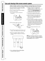
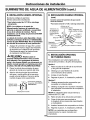
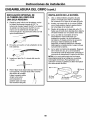
FEED WATER SUPPLY (cont,)
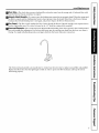
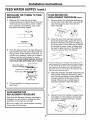
INSTALLING THE TUBING TO TANK
AND FAUCET
1.
Measure 3/4" from the end of each
remaining piece of tubing (faucet end and
inlet end) and mark with a pencil. (Check
for roundness, smoothness, cuts, nicks,
flat spots and sharp edges).
INCORRECT
.
.
Push the tubing firmly into each fitting on
the manifold until the line is flush with the
fitting collar. (If the tubing is removed, re-
cut the end, measure, mark and re-insert).
Tubing must be fully inserted to avoid
leaks. To remove tubing: depress and hold
red or blue collet; pull tubing out to remove.
Red or Blue Collet __///////_/
(DO NOT REMOVE) _/.
Insertion I_
Insert tubing _
_{3 ngagemenL_
3/4" -I
/8" tubing) i
Pull out slightly on tubing to ensure a
good seal.
FLOW RESTRICTOR
REPLACEMENT PROCEDURE
Each time the Reverse Osmosis cartridge is
changed, you will need to replace the flow
restrictor in the drain line as well.
Be sure to wash your hands before handling
inner parts of the system.
FLOW RESTRICTOR
REPLACEMENT PROCEDURE (cont.)
1,
Remove drain line tubing by pushing up
on the drain line collet with one hand (1)
and removing the drain line with the
other hand (2).
, Once the drain line has been removed
from the system base, grasp the end of
the flow restrictor and pull it straight out
from the tube*. If the restrictor is difficult
to remove by hand, a pair of pliers may
be used to grip the end of the restrictor
to aid in removal from the tubing.
*In some instances, the restrictor may slide out of the
dra_n tubing as it is removed from the drain line port.
If, after removing the drain line as described _n step 1,
the restrictor is no longer in the end of the tubing,
check the drain line port. Remove the restr_ctor from
the port and proceed to step 3.
, Take new restrictor and slide it back into the
drain tubing. Insert the restrictor by hand
only. Do not use pliers to insert. Make sure
to insert restrictor all the way into the
tubing. Failure to do so could result in
improper operation of the RO system.
4,
Reinsert drain line tubing in system base.
Tug lightly on the tubing to ensure that
the collet is engaged and has a proper
grip on the tubing.
12

Installation Instructions
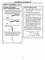
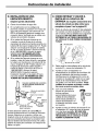
FAUCET ASSEMBLY
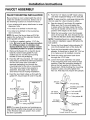
FAUCET MOUNTING INSTALLATION
Be sure there is room underneath the sink to
make the needed connections. Select one of
the following locations to install the faucet:
• In an existing sink spray attachment or soap
dispenser hole.
• In a hole to be drilled in the sink top.
• In a hole to be drilled in the countertop,
next to the sink.
NOTE: Be sure the faucet base will fit flat
against the surface at the selected location
so the gasket will seal.
1.
.
.
4.
If drilling is needed, make a 1-1/4" dia.
hole. Be sure to use the proper procedure
for drilling porcelain or stainless steel.
Special drill bits may be needed. Consult
a qualified plumber for proper procedure.
Remove the faucet, thin o-ring (D), faucet
base (E), bottom base gasket (F), lock
washer (G), hex nut (H) and mounting
bracket (I) from the packaging.
Feed the 3/8" blue banded, 1/4" black tube
(attached to the Reverse Osmosis System)
and the 3/8" black tube (included in
separate packaging) up through the
mounting hole in the sink or countertop.
This step may require two people to
assemble. See page 14 for Optional
One Person Faucet Tubing Installation.
Feed the two black tubes up through the
gasket (F), faucet base (E) and O-ring (D).
_:_ Spout
Cap
Body {B) _ Handle
O*rlng (D)
_j Base (E)
Mounting _..j Gasket (F)
bracket (I)"_.__,_W Lock washer (G)
_t- Hex nut (H)
_"_ Tubing adapter (K)
nn n
ASSEMBLED
NOTE: For ease of service and maintenance,
keep tubing lengths long enough so removal
of the Reverse Osmosis system from under
the sink is possible.
5. Push the 1/4" black and 3/8" black tubing
onto their respective fittings on the body (B).
NOTE: To ease insertion, submerge tubing ends
into hot water for a few minutes to soften.
.
Seat the base (E) and body (B) together.
Make sure the O-ring and gasket are
in place when the base meets the body.
The faucet handle will be at the 3 o'clock
position with respect to the base.
7. Slide the lock washer onto the threaded
stem of the body (B), then thread the hex
nut (H) onto the stem. Screw about halfway up.
NOTE: If installing faucet on a stainless steel
sink, slide on installation spacer (M) before the
lock washer.
8. Screw the blue tipped tubing adapter (K)
onto the threaded stem of the body (B).
9. Push the blue banded tubing into the
adapter. It should go in about 3/4". Pull on
it to make sure it is installed correctly.
10.
11.
Feed the tubing and stem back down
through the 1-1/4" hole.
Lower the faucet assembly into place
in the mounting hole and orient to final
position. Place the mounting bracket (I)
above the lock washer (G) around the
faucet stem. While holding the mounting
bracket in place, securely tighten the
hex nut. This step may require two people.
3/8" barb
3/8' (black)
drain tubin_
1/4" (black)
drain tubing
4" barb fitting
Installation spacer (M)
3sneeded)
IG)
Hex Nut (H)
g adapter {K)
3/8" (blue banded)
outlet tubing
To drain From RO From RO
13

Installation Instructions
FAUCET ASSEMBLY (cont,)
OPTIONAL ONE PERSON
FAUCET TUBING INSTALLATION
1.
From under the sink, gather the 1/4" drain
line (black), 3/8" drain line (black) and 3/8"
outlet tube (blue banded) in one hand with
the drain tubes the same length and the
outlet tube offset approximately 6 inches.
2. Wrap a rubber band around all 3 tubes.
3. Insert a typical No. 2 pencil through the
rubber band location.
4.
Rotate the pencil down until it is in line
with the tubing and push up through the
mounting hole. Release the grip on the
pencil and the tubes will remain in
position for easier faucet connection.
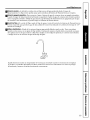
BATTERY INSTALLATION
1,
2.
3.
4.
Use a small flat blade screwdriver or coin
to remove the battery tray (A) at the side
of the faucet base.
Install one CR2032, 3 volt battery (B)
+ side down into the battery tray (A).
Slide tray into faucet base (C) until the
battery tray (A) edge is flush with the side
of the base.
The blue light (D) will flash 5 times,
indicating a proper installation and system
reset. If you want to reinitiate the start-up
sequence, remove the battery for 45-60
seconds; the electronics need to fully
discharge. Then put the battery back in.
5. The light is normally off. After 6 months
of use, the light will flash again every
30 seconds, indicating the proper time
to replace the filter cartridge.
NOTE: The blue light may stop blinking if
allowed to blink for an extended period of
time. To ensure proper operation, the battery
should be replaced with every filter change.
(D) Blue light _ (B) Battery
J AB
(C) Faucet base ( ) atta_....._@
tray
14

Installation Instructions
FILTRATION DRAIN CONNECTION
Check and comply with local plumbing codes as you plan.
CAUTION: The options detailed below are the ONLY approved installation
configurations. Do not use any drain saddle device.
NOTE: Failure to follow these Installation Instructions will void the warranty, and the installer will
be responsible for any service, repair or damages caused thereby.
PREFERRED INSTALLATION:
OPTION AmBASEMENT ACCESS
INSTALLATION
Route the drain line DIRECTLY from the Reverse
Osmosis system to a standpipe in the basement,
bypassing the air gap provided in the faucet. The
air gap installation is left to the discretion of the
installer. The drain line may also be routed to a
floor drain or washtub, provided that the air gap
is maintained. Special air gap fittings are available
to connect the drain line to the top of the standpipe.
Drain llne from the Reverse Osmosis system
1" m_n_mum air gap
must be maintained
PREFERRED INSTALLATION:
OPTION B--ORY-VENTED P-TRAP
INSTALLATION
Install a separate dry-vented p-trap under the
sink to be used exclusively for the Reserve
Osmosis drain line. A dry-vented p-trap is a
p-trap that has its own vent/stack. Attach the
drain line adapter to the p-trap and secure it
with the slip joint nut and washer as shown.
The drain line MUST be routed through the air
gap provided in the RO water faucet.
Reverse "_ _ _"
Osmosis _ _
drain llne _1] ,/[I- i
___J
Opti " oser
15

Installation Instructions
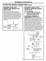
FILTRATION DRAIN CONNECTION (cont.)
PREFERRED INSTALLATION:
OPTION C--WET-VENTED P-TRAP
INSTALLATION
Install a p-trap under the sink to be used
exclusively for the Reverse Osmosis drain line.
A wet-vented p-trap is a p-trap that shares a
common vent/stack. Attach the drain line adapter
to the p-trap and secure it with the slip joint nut
and washer as shown. The drain line MUST be
routed through the air gap provided in the RO
water faucet. Locate the Reverse Osmosis p-trap
as high as possible (minimum of 4" above
horizontal).
Reverse _t'_'_'L i! JJ Ir
Osmosis / I t"_"t J I " I
drain,he k',fl "---'
_) _ Optional d_sposer
SECONDARY INSTALLATION:
OPTION DmDRAIN LINE ADAPTER
INSTALLATION
CAUTION: Using Option O
may result in clogging under adverse
conditions and requires periodic
inspection/cleaning by the user.
DO NOT INSTALL THE DRAIN UNE
DOWNSTREAM OF A DISPOSER OR IN A
HORIZONTAL PIPE. Install the drain line adapter
under the sink as shown (parts included). The
baffle tee shown must be installed to prevent a
clog in the Reverse Osmosis drain line. Route the
drain line from the air gap to the drain line
adapter, ensuring that there are no dips, loops or
low spots in the line. The drain line adapter
should be aligned vertically so that the hose
connection points upward (the hose connection
should never be allowed to drop below 45° from
this vertical position). This installation MAY result
in a slight drain noise in the sink drain when the
Reverse Osmosis system is regenerating. If this
happens, simply place the sink drain stoppers
in the strainer to suppress it.
Maximum 45°
verse
smosis
ain line
^T, II F Drainline
Optional II ft_ _5311z_'
_'y "'_.,'"' t,.U] adapter
disposer _ -_-"'-"
Fro'(_m'_
second sink \ Drain line connection should
or disposer be 180° opposite existing
horizontal pipe/baffle-tee as
shown in diagram
16
Proper drain line adapter orientation.
_n line adapter

Installation Instructions
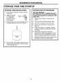
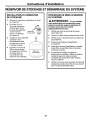
STORAGE TANK AND STARTUP
STORAGE TANK INSTALLATION
1.
2.
.
Remove the protective cap from the top
of the tank.
Apply 2-3 wraps
of thread tape,
in a clockwise
direction, to the
tank threads.
Install the push-to-connect fittings on the
threaded fitting on the tank as shown.
4.
Storage
tank
Push the 3/8" red banded tubing from the
Reverse Osmosis System into the fitting
on the storage tank.
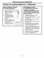
SYSTEM STARTUP PROCEDURE
A_^| |-i-=r_R,
LLt.p/'_U/IUI_I: If installing the unit in
new construction, ensure that house plumbing
is flushed thoroughly before opening the water
supply valve.
1. Check that all tubing connections are
secure.
2. Turn on the Feed Water Supply Valve.
3. Check all connection points for leaks.
4. Follow the Sanitization procedures on
page 19.
5. After sanitization is complete, reinstall
prefilter, postfilter and Reverse Osmosis
cartridges.
6. Membrane contains a food grade
preservative. Allow the system to fill the
tank, then drain it completely four times
before using the water from the system.
7. Recheck all water connection points a few
days later to check for small leaks.
17

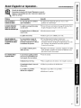
Careand cleaningofthereverse osmosissystem.
Prefilter, Postfilter and Reverse Osmosis Membrane Cartridge Replacement Procedure
Wheu tile hlue light in tile fbucet hase flashes, 6. ReInove fbil on top of uew replacement
it is liIite lo replace the prefiher and postfiher.
This will occur every 6 months.
Be sure to wash your hands befi)re haudliug
inner parts of tile sys/eIn.
I. "Ibm OFF tile icema_er (ifatlached m
flle system).
2. "Ibm offwater supply m die sysleIll.
cartridges. Install new cartridges into Ihe
mmfifbld hy mining m tile fight about 1/3 turn
until dm aligmnent marks line tip mid Ihe
cartridges stop. DO NOTOVBCTI6HIEN. Tile
cartridges will rise tip as alley are mined.
Z Turn ON water supply m fill die systetll
(maytake up m fimr hours). Check for leaks.
ReInove ltle battery tray aud replace tile
bal/ery to remt fiIner and monilor fimction
in faucet ba.'.;e(_e BatteryInstallationfbr
proper procedure).
9.
If only tile prefiher and postfiher are replaced,
mm the fbucet ON and empty the filled storage
lauk. If the memhraue cartridge is replaced, fill
aud emp/y tile storage rauk a total of four times.
(This will remuve the food grade preservatives
contained in new membraues. This premrvafive
will give product water an unplea-sm_t tasle
and eden)
I0. Once dm storage tauk is thll, mm ou file
iceInaker.
3. Turn ON faucet to draintauk (may take several
Ininutes). Turn OFF faucet when tauk is emp/y.
4. Remove tile prefilter, postfilter aud Reverm
Osmosis cartridge hy rulafing to file left about
1/3 ram.
Prefi[terl Reve_el
Osmosisl Postfi[tel
NOTE.,"System should he sauifized when replacing
file prefiher aud poslfiher carlridge or the Reverse
Osmosis cartridge. Follow the Sanitizing tha Reverse
Osmosis Systam procedure on page 19.
Toremove
Follow Sanitizing the Reverse Osmosis System
procedure found on page 19.
18

www.GEAppliances.com
Sanitizing the Reverse Osmosis System
Sanitize upon installadon of the Reverse OsIllosis
systeln and after ser_4cing inner parts, including
replacement of prefilter, posttiher and the
IneInbrane cartridge.
Be sure to wash your bands before handling
inner parts of the syslem.
A CAUTION:_ef_,re smlidzing, be sure to
remove all carlridges. (iblorine will destruy tile
Reverse Osmosis Inembrane carlridge.
I. Follow steps 1 through 4 under Prefiltor,
Posffilter and Reverse Osmosis Membrane Cartridge
Replacement Procedure.
2 Fill file eInpty caIfister labeled "Sanifizalion
C_mister" wifll waler lx_within 1 inch of die
tipper opening. Add 1 oz. (2 Tbsp.) ordinary
household bleach. Install canister into tile
prefilter canister position by turning m the right
aixmt 1/3 mm until die _ligmment Inark_; line
up and die canister stops.
"_-.,..,...,_ Prefilter
position
3. Install die two additional "sanifiziafion cmfislers"
inlo die meInbrane canister and postflher
openings in die manifold by turlling to lbe right
aixmt 1/3 mm until die aligmment marks line
up and die canismr stops.
4. Turn ON waler supply. Turn ON fimcet until
W_alerbegins lo flow from 1tie faucet, then Illrn
tZaucel OFE Allow system m fill for 10 minutes.
5. TurIl fhucet ON and allow water m flow fbr 20
minutes, or until bleach udor is gune. "Ibm OFF
waler supply again. "I_m ON faucet m drain
tile sys/eIn.
6. Once die system is drained, mm tile fhucet OFF
and remove tile canisters by mining m die left
about 1/3 turn. Keep the_ in a safe place undl
needed tile next time.
Sanitization
canisters 79

Careand cleaningofthereverse osmosissystem.
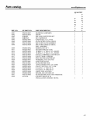
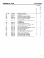
To obtain replacement filters, call toll-free GE Appfiance Parts at 800.626.2002 (UoS.),
800.663.6060 (Canada-English), 800.361.3869 (Canada-French), or visit the store where
you purchased your reverse osmosis system.
Pmfilter/PostfilterCartridgeReplacementFQROPF t CadJonBIock
Reverse OsmosisCartridge Replacement FQROMF ThinFilm Polyamide
A_ I'J AI,_I.IUTION; Before servicing the Reverse Osmosis system, close the water supply/saddle valve
and open the RO water faucet. Allow the system to drain.
The Water Test Kit
To obtain an independent laboratory water test kit, please call Legend Technical Services at
1.800.826.8553 ext. 47 and leave your conlact details. They will contact you to find out what wa/er
lests you are interested in, and infi)rIn you of the cost of the testing. You will then receive a kit that
will include all necessary tests to properly indicate the perfi)rmance level of your system. Product
water should be lested a minimum of every six monlhs.
NOTE:When the TDS reduction of the system falls below 75%, it is time to replace the reverse
osmosis carlridge in addition to the prefilter and pos/filter.
2O
La page est en cours de chargement...
La page est en cours de chargement...
La page est en cours de chargement...
La page est en cours de chargement...
La page est en cours de chargement...
La page est en cours de chargement...
La page est en cours de chargement...
La page est en cours de chargement...
La page est en cours de chargement...
La page est en cours de chargement...
La page est en cours de chargement...
La page est en cours de chargement...
La page est en cours de chargement...
La page est en cours de chargement...
La page est en cours de chargement...
La page est en cours de chargement...
La page est en cours de chargement...
La page est en cours de chargement...
La page est en cours de chargement...
La page est en cours de chargement...
La page est en cours de chargement...
La page est en cours de chargement...
La page est en cours de chargement...
La page est en cours de chargement...
La page est en cours de chargement...
La page est en cours de chargement...
La page est en cours de chargement...
La page est en cours de chargement...
La page est en cours de chargement...
La page est en cours de chargement...
La page est en cours de chargement...
La page est en cours de chargement...
La page est en cours de chargement...
La page est en cours de chargement...
La page est en cours de chargement...
La page est en cours de chargement...
La page est en cours de chargement...
La page est en cours de chargement...
La page est en cours de chargement...
La page est en cours de chargement...
La page est en cours de chargement...
La page est en cours de chargement...
La page est en cours de chargement...
La page est en cours de chargement...
La page est en cours de chargement...
La page est en cours de chargement...
La page est en cours de chargement...
La page est en cours de chargement...
La page est en cours de chargement...
La page est en cours de chargement...
La page est en cours de chargement...
La page est en cours de chargement...
La page est en cours de chargement...
La page est en cours de chargement...
La page est en cours de chargement...
La page est en cours de chargement...
La page est en cours de chargement...
La page est en cours de chargement...
La page est en cours de chargement...
La page est en cours de chargement...
La page est en cours de chargement...
La page est en cours de chargement...
La page est en cours de chargement...
La page est en cours de chargement...
-
 1
1
-
 2
2
-
 3
3
-
 4
4
-
 5
5
-
 6
6
-
 7
7
-
 8
8
-
 9
9
-
 10
10
-
 11
11
-
 12
12
-
 13
13
-
 14
14
-
 15
15
-
 16
16
-
 17
17
-
 18
18
-
 19
19
-
 20
20
-
 21
21
-
 22
22
-
 23
23
-
 24
24
-
 25
25
-
 26
26
-
 27
27
-
 28
28
-
 29
29
-
 30
30
-
 31
31
-
 32
32
-
 33
33
-
 34
34
-
 35
35
-
 36
36
-
 37
37
-
 38
38
-
 39
39
-
 40
40
-
 41
41
-
 42
42
-
 43
43
-
 44
44
-
 45
45
-
 46
46
-
 47
47
-
 48
48
-
 49
49
-
 50
50
-
 51
51
-
 52
52
-
 53
53
-
 54
54
-
 55
55
-
 56
56
-
 57
57
-
 58
58
-
 59
59
-
 60
60
-
 61
61
-
 62
62
-
 63
63
-
 64
64
-
 65
65
-
 66
66
-
 67
67
-
 68
68
-
 69
69
-
 70
70
-
 71
71
-
 72
72
-
 73
73
-
 74
74
-
 75
75
-
 76
76
-
 77
77
-
 78
78
-
 79
79
-
 80
80
-
 81
81
-
 82
82
-
 83
83
-
 84
84


GE PNRQ15FBL00 Le manuel du propriétaire
- Taper
- Le manuel du propriétaire
dans d''autres langues
- English: GE PNRQ15FBL00 Owner's manual
- español: GE PNRQ15FBL00 El manual del propietario
Documents connexes
-
GE PNRQ20FWW00 Le manuel du propriétaire
-
-
-
-
-
-
-
-
-
GE PNRQ21RRB Manuel utilisateur
