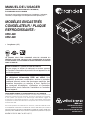
Randell 9550-290 & 9552-290 Drop-In Manuel utilisateur
- Taper
- Manuel utilisateur

This manual provides information on installation, operating,
maintenance, trouble shooting & replacement parts for:
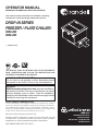
OPERATOR MANUAL
IMPORTANT INFORMATION, KEEP FOR OPERATOR
PART NUMBER PP MNL1702, REV D (08/17)
DROP-IN SERIES
FREEZER / PLATE CHILLER:
9550-290
9552-290
• Freezer (-5ºF)
Information contained in this document is known to be current and accurate at the time
of printing/creation. Unified Brands recommends referencing our product line websites,
unifiedbrands.net, for the most updated product information and specifications.
1055 Mendell Davis Drive
Jackson, MS 39272
888-994-7636, fax 888-864-7636
unifiedbrands.net
THIS MANUAL MUST BE RETAINED FOR FUTURE REFERENCE.
READ, UNDERSTAND AND FOLLOW THE INSTRUCTIONS AND
WARNINGS CONTAINED IN THIS MANUAL.
WARNING / FOR YOUR SAFETY
Do not store or use gasoline or other ammable vapors
and liquids in the vicinity of this or any other appliance.
WARNING
R290 ammable refrigerant in use. Improper installation,
adjustment, alteration, service or maintenance can cause
property damage, injury or death. Read the installation,
operating and maintenance instructions thoroughly before
installing or servicing this equipment.
NOTIFY CARRIER OF DAMAGE AT ONCE
It is the responsibility of the consignee to inspect the container upon receipt of
same and to determine the possibility of any damage, including concealed dam-
age. Unied Brands suggests that if you are suspicious of damage to make a
notation on the delivery receipt. It will be the responsibility of the consignee to le
a claim with the carrier. We recommend that you do so at once.
Manufacture Service/Questions 888-994-7636.

2 OM-DROP-IN SERIES
Important Operator Notices ......................................................... page 3
Labeling ..................................................................................... page 4-5
Equipment Description .................................................................. page 6
Installation ................................................................................. page 7-8
Operation ................................................................................ page 9-10
Maintenance ................................................................................ page 11
Troubleshooting ........................................................................... page 12
Service ........................................................................................ page 13
Parts List ...................................................................................... page 14
Electrical Schematic ................................................................... page 15
Service Log ................................................................................. page 16
Warranty Policies .................................................................... page 17-19
Table of Contents

OM-DROP-IN SERIES 3
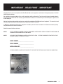
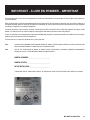
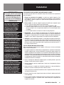
IMPORTANT - READ FIRST - IMPORTANT
Congratulations on your recent purchase of Unified Brands food service equipment, and welcome to the growing family of satisfied
Unified Brands customers.
Our reputation for superior products is the result of consistent quality craftsmanship. From the earliest stages of product design to
successive steps in fabrication and assembly, rigid standards of excellence are maintained by out staff of designers, engineers, and
skilled employees.
Only the finest heavy-duty materials and parts are used in the production of Unified Brands brand equipment. This means that each
unit, given proper maintenance will provide years of trouble free service to its owner.
In addition, all Unified Brands food service equipment is backed by some of the best warranties in the food service industry and by
our professional staff of service technicians.
Retain this manual for future reference.
NOTICE: DUE TO A CONTINUOUS PROGRAM OF PRODUCT IMPROVEMENT, UNIFIED BRANDS RESERVES THE RIGHT TO MAKE CHANGES IN
DESIGN AND SPECIFICATIONS WITHOUT PRIOR NOTICE.
NOTICE: PLEASE READ THE ENTIRE MANUAL CAREFULLY BEFORE INSTALLATION. IF CERTAIN RECOMMENDED PROCEDURES ARE NOT
FOLLOWED, WARRANTY CLAIMS WILL BE DENIED.
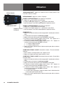
MODEL NUMBER _________________________
SERIAL NUMBER _________________________
INSTALLATION DATE ______________________
THE SERIAL NUMBER IS LOCATED IN THE CABINET LEFT SIDE UNDER THE ELECTRICAL BOX. AN EXAMPLE IS SHOWN BELOW.

4 OM-DROP-IN SERIES
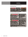
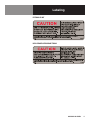
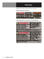
The following warning labels will be found on your equipment:
INTERIOR EVAPORATOR COVER
NEAR MACHINE COMPARTMENT AND NAMEPLATE
Labeling

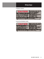
OM-DROP-IN SERIES 5
EXTERIOR OF UNIT
NEAR EXPOSED REFRIGERANT TUBING
Labeling

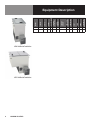
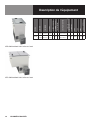
6 OM-DROP-IN SERIES
Equipment Description
MODEL
LENGTH
DEPTH
HEIGHT
NO. OF OPENINGS
STORAGE
(CUBIC FEET)
GALLON
CAPACITY
COUNTER
CUTOUT
POWER USAGE
KW (PER DAY)
COMPRESSOR
VOLT
AMPS
NEMA
SHIP WT (LBS)
9550-290 28.375” 17.1875” 27” 1 1.8 6 26" x 15.75" 0.95 1/4 115/60/1 2.0 5-15P
125
9552-290 28.375” 28.375” 27” 1 3.36 11.2 26" x 26" 1.34 1/4 115/60/1 2.0 5-15P
165
9550-290 Back to Front Airflow
9552-290 Back to Front Airflow

OM-DROP-IN SERIES 7
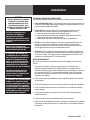
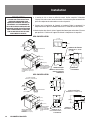
Installation
SELECTING A LOCATION FOR YOUR NEW UNIT
The following conditions should be considered when selecting a location for your unit:
1. Floor and Countertop Load: The area on which the unit will rest must be level, free
of vibration, and suitably strong enough to support the combined weights of the unit
plus the maximum product load weight.
2. Secure and Seal: Once the drop in unit is installed into the counter it can be
secured to the countertop by using the brackets supplied from the factory.
a. Secure unit to top and seal with “NSF” approved silicone.
b. Install inside duct with thumb screws and adjust outside duct to fit between
condenser coil and counter’s louvered cutout
c. Secure outside duct in place with screws through pre-punched holes.
3. Clearance: See installation diagrams for minimum compartment dimension. Do
not place any object that can block the ventilation exhaust from the machine
compartment register. 10 inch clearance at each of the louvered ends of the unit.
Area of equipment must be free of all combustible materials.
4. Ventilation: The air cooled self contained unit requires a sufficient amount of cool
clean air. Avoid surrounding your unit around other heat generating equipment and
out of direct sunlight. Also, avoid locating in an unheated room or where the room
temperature may drop below 55°F or rise above 86°F.
INSTALLATION CHECKLIST
After the final location has been determined, refer to the following checklist prior to
start-up:
1. Units must be installed in a minimum compartment size as indicated in the
installation drawing. Provided louvers must be installed in accordance with the
installation drawings to ensure proper ventilation for system operation or in the event
of a refrigerant leak. NOTE: It is recommended that ONLY a single GFCI outlet be
located in the compartment where the unit is installed. No other arching potential
components are allowed.
2. Follow cut out dimensions provided for specific models to properly size the opening
for your drop in.
3. Check cord and plug of unit to assure no damage has occurred to these components.
4. Check all exposed refrigeration lines to ensure that they are not kinked, dented, or
rubbing together.
5. Check that the condenser and evaporator fans rotate freely without striking any
stationary members.
6. Plug in unit and turn on main on/off power button on the controller.
7. Allow unit time to cool down to temperature. If temperature adjustments are required,
the control is located on the front panel. Confirm that the unit is holding the desired
temperature.
IT IS IMPORTANT THAT A VOLTAGE READING
BE MADE AT THE COMPRESSOR MOTOR
ELECTRICAL CONNECTIONS, WHILE THE UNIT
IS IN OPERATION TO VERIFY THE CORRECT
VOLTAGE REQUIRED BY THE COMPRESSOR
IS BEING SUPPLIED. LOW OR HIGH VOLTAGE
CAN DETRIMENTALLY AFFECT OPERATION
AND THEREBY VOID ITS WARRANTY.
CAUTION!
THIS UNIT CONTAINS R290 FLAMMABLE
REFRIGERANT. USE CAUTION WHEN
HANDLING MOVING AND USE OF THE
REFRIGERATOR OR FREEZER. AVOID
DAMAGING THE REFRIGERANT TUBING OR
INCREASE THE RISK OF A LEAK.
FAILURE TO FOLLOW INSTALLATION
GUIDELINES AND RECOMMENDATIONS MAY
VOID THE WARRANTY ON YOUR UNIT.
IT IS IMPORTANT THAT YOUR UNIT HAS
ITS OWN DEDICATED LINE. CONDENSING
UNITS ARE DESIGNED TO OPERATE WITH
A VOLTAGE FLUCTUATION OF PLUS OR
MINUS 10% OF THE VOLTAGE INDICATED
ON THE UNIT DATA TAG. BURN OUT OF A
CONDENSING UNIT DUE TO EXCEEDING
VOLTAGE LIMITS WILL VOID THE WARRANTY.
THE DANFOSS CONTROLLER HAS LOW
VOLTAGE PROTECTION AND WILL NOT
OUTPUT VOLTAGE TO THE COMPRESSOR IF
VOLTAGE IS LESS THAN 104V.
THIS UNIT IS INTENDED FOR USE IN
LABORATORIES IN COMMERCIAL,
INDUSTRIAL, OR INSTITUTIONAL
OCCUPANCIES AS DEFINED IN THE SAFETY
STANDARD FOR REFRIGERATION SYSTEMS,
ASHRAE 15.

8 OM-DROP-IN SERIES
Installation
8. Refer to the front of this manual for serial number location. Please record this
information in your manual on page 3 now. It will be necessary when ordering
replacement parts or requesting warranty service.
9. Confirm that the unit is holding temperature. Set control to desired temperature for
your particular ambient and altitude.
10. Before putting in product, allow your unit to operate for approximately two (2) hours
so that interior of the unit is cooled down to storage temperature.
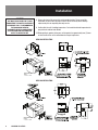
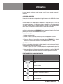
9550-290 INSTALLATION
MINIMUM BOX
DIMENSIONS,
30" DEEP X 20" WIDE
MINIMUM BOX
DIMENSIONS,
30" DEEP X 30" WIDE
MINIMUM BOX
DIMENSIONS,
30" DEEP X 20" WIDE
MINIMUM BOX
DIMENSIONS,
30" DEEP X 30" WIDE
MINIMUM BOX
DIMENSIONS,
30" DEEP X 20" WIDE
MINIMUM BOX
DIMENSIONS,
30" DEEP X 30" WIDE
MINIMUM BOX
DIMENSIONS,
30" DEEP X 20" WIDE
MINIMUM BOX
DIMENSIONS,
30" DEEP X 30" WIDE
MINIMUM BOX
DIMENSIONS,
30" DEEP X 20" WIDE
MINIMUM BOX
DIMENSIONS,
30" DEEP X 30" WIDE
9552-290 INSTALLATION
CAUTION!
UNIT MUST BE INSTALLED INTO IT’S OWN
COMPARTMENT TO PROPERLY CONTAIN ANY
REFRIGERANT LEAK. IT IS RECOMMENDED
THAT NO ARCHING POTENTIAL
COMPONENTS BE IN THIS COMPARTMENT
WITH THE EXCEPTION OF A SINGLE GFCI
OUTLET TO POWER THE UNIT.
COMPARTMENT
COMPARTMENT

OM-DROP-IN SERIES 9
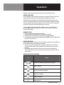
Operation
Allow unit to operate for approximately two (2) hours before placing in food.
AMBIENT CONDITIONS
Unit is designed for normal operating temperatures are between 70-100°F. Operating
outside of those temperatures may cause premature product wear or failure
Unified Brands has attempted to preset the temperature control to ensure that your
unit runs at an optimum temperature, but due to varying ambient conditions, including
elevation, food type and your type of operation, you may need to alter this temperature
using control adjustment until desired temperature is reached.
It is normal for the refrigerated cold well to develop an even layer of frost during
operation. NOTE: Keeping the hinged cover closed as much as possible will prevent
excessive frost buildup.
MORNING STARTUP
1. Cold pan cleaning may be performed at this time.
2. Turn on unit with switch located in the mechanical compartment.
3. Allow 30 minutes for the cold pan to cool down before loading product.
4. Load the product and proceed with food preparation. NOTE: Product entering the cold
pan must be at 40°F or less.
EVENING SHUT DOWN
Remove product from the cold pan at the end of the day’s preparation. The product may
be discarded or stored in any commercial refrigerator.
1. Turn off unit with switch located in the mechanical compartment. This will allow
unit to thaw which allows for better operation when starting up unit for next day
operation.
2. Unit cleaning may be performed at this time once the frost has melted off the
surface. NOTE: Water may form small pools and have to be pushed to the drain for
100% draining.
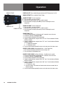
DANFOSS CONTROLLER OPERATION
LED FUNCTION
Compressor energized & Evaporator fan de-energized
Defrost in progress
Fans delay after defrost completion
Evaporator fan energize
An alarm is occurring
ºC / ºF Temperature unit

10 OM-DROP-IN SERIES
POWER ON / OFF
MANUAL DEFROST
CHANGE SET POINT
Operation
POWER ON / OFF: Press and hold the power button until LED display turns On / Off
MANUAL DEFROST: Press and hold “Defrost” Button
CHANGE SET POINT: To raise temperature
1. Press and hold “
” to access set point.
2. When set point start flashing, Press “
” to adjust set point
3. After 30 seconds, the display automatically reverts to showing the current
temperature
CHANGE SET POINT: To lower temperature
1. Press and hold “v” to access set point
2. When set point start flashing, Press “v” to adjust set point
3. After 30 seconds, the display automatically reverts to showing the current
temperature
CHANGE FROM ºF /ºC :
1. Press the up/down buttons simultaneously for 5 seconds to access the menu.
2. Password is requested. Password is 000.
3. Press the bottom left button to OK the password.
4. Using the up/down buttons, navigate to the “diS” level. Press the bottom left button
to OK the selection.
5. Using the up/down buttons, navigate to the “CFu” level. Press the bottom left button
to OK the selection.
a. “-F” designates Fahrenheit.
b. “-C” designates Celsius.
6. Press the top left button repeatedly to return to exit and return to the home screen.
DRAWER / DOOR ALARM: Acknowledging Alarms – Visual Display Only
1. After 2 minutes the display will flash the alarm message “dor”
2. Press any button to acknowledge alarm
DRAWER / DOOR ALARM: Door Alarm Activation – If audible alarm is wanted
1. Press the up/down buttons simultaneously for 5 seconds to access the menu.
2. Password is requested. Password is 000.
3. Press the bottom left button to OK the password.
4. Using the up/down buttons, navigate to the “ALA” level. Press the bottom left button
to OK the selection.
5. Using the up/down buttons, navigate to the “Abd” level. Press the bottom left button
to OK the selection.
a. “0” Disables the alarm.
b. Any other number is the number of minutes before the buzzer sounds after the
drawer is opened.
6. Press the top left button repeatedly to return to exit and return to the home screen.

OM-DROP-IN SERIES 11
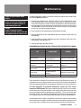
Maintenance
Unified Brands strongly suggests a preventive maintenance program which would include
the following Monthly procedures:
1. Cleaning of all condenser coils. Condenser coils are a critical component in the life
of the compressor and must remain clean to assure proper air flow and heat transfer.
Failure to maintain this heat transfer will affect unit performance and eventually destroy
the compressor. Clean the condenser coils with coil cleaner and/or a vacuum cleaner
and brush. NOTE: Brush coil in direction of fins, normally vertically as to not damage
or restrict air from passing through condenser.
2. Clean fan blades on the condensing unit and evaporator assembly.
3. Clean and disinfect drain lines and evaporator pan with a solution of warm water and
mild detergent.
4. Clean all gaskets on a weekly if not daily basis with a solution of warm water and a
mild detergent to extend gasket life.
5. Lubricate door hinges with lithium grease.
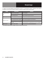
RECOMMENDED CLEANERS FOR YOUR STAINLESS STEEL INCLUDE THE FOLLOWING:
JOB CLEANING AGENT COMMENTS
Routine cleaning
Soap, ammonia,
detergent Medallion
Apply with a sponge or cloth
Fingerprints and smears Arcal 20, Lac-O-Nu, Ecoshine Provides a barrier film
Stubborn stains and
discoloration
Cameo, Talc, Zud,
First Impression
Rub in the direction of the
polish lines
Greasy and fatty acids, blood,
burnt-on foods
Easy-Off, Degrease It,
Oven Aid
Excellent removal on all
finishes
Grease and Oil
Any good commercial
detergent
Apply with a sponge or cloth
Restoration/Preservation Benefit, Super Sheen Good idea monthly
Reference: Nickel Development Institute, Diversey Lever, Savin, Ecolab, NAFEM
Proper maintenance of equipment is the ultimate necessity in preventing costly repairs. By
evaluating each unit on a regular schedule, you can often catch and repair minor problems
before they completely disable the unit and become burdensome on your entire operation.
For more information on preventive maintenance, consult your local service
company or CFESA member. Most repair companies offer this service at very reasonable
rates to allow you the time you need to run your business along with the peace of mind
that all your equipment will last throughout its expected life. These services often offer
guarantees as well as the flexibility in scheduling or maintenance for your convenience.
For a complete listing of current Unified Brands ASA please visit www.unifiedbrands.net.
Unified Brands believes strongly in the products it manufactures and backs those products
with one of the best warranties in the industry. We believe with the proper maintenance and
use, you will realize a profitable return on your investment and years of satisfied service.
DO NOT USE SHARP UTENSILS AND/OR
OBJECTS.
CAUTION
DO NOT USE ABRASIVE CLEANING
SOLVENTS, AND NEVER USE HYDROCHLORIC
ACID (MURIATIC ACID) ON STAINLESS STEEL.
DO NOT USE STEEL PADS, WIRE BRUSHES,
SCRAPERS, OR CHLORIDE CLEANERS TO
CLEAN YOUR STAINLESS STEEL.

12 OM-DROP-IN SERIES
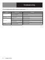
Troubleshooting
This unit is designed to operate smoothly and efficiently if properly maintained. However, the following is a list of checks to make in
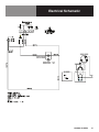
the event of a problem. Wiring diagrams are found at the end of this manual.
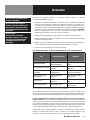
SYMPTOM POSSIBLE CAUSE PROCEDURE
Unit does not run
No power to unit Plug in unit
Control in OFF position Turn controller on
Faulty control Call for service at 888-994-7636
Unit too cold Incorrect set point Adjust control set point
Unit too warm
Lid open Ensure lid is fully closed
Gasket torn or out of place Inspect the gasket for wear and position
Incorrect set point Adjust control set point
Warm product introduced to cabinet Pre-chill product -3ºF for freezer
Unit noisy Vibration in the cabinet Inspect for loose parts
When in doubt, turn unit off and call for service at 888-994-7636.

OM-DROP-IN SERIES 13
Service
This piece of equipment uses a R290 Refrigeration system. This equipment has been
clearly marked on the serial tag the type of refrigerant that is being used. There is also a
warning labels stating that the unit contains R290 refrigerant.
No smoking or open flames when servicing this equipment. If needed, use a CO
2
or
dry=power type fire extinguisher
Only authorized service technician, certified in R290 system should service this equipment.
MANIFOLD SET
A R134A manifold set can be used for servicing this equipment.
REFRIGERANT RECOVERY
Follow all national and local regulations for R-290 refrigerant recovery.
LEAKING CHECKING AND REPAIR
Leak check an R290 system the same way you would an R134a or R404A system with
the following exceptions.
1. Do not use a Halid leak detector on a R290 system.
2. Electronic leak detector must be designated specifically for combustible gas.
Use of a bubble solution or an ultrasonic leak detector are acceptable.
When repairing a leak, it is recommended using oxygen free dry nitrogen with a trace gas
not exceeding 200PSI.
When accessing an R290 system, piercing valves are not to remain on the equipment in
a permanent manner. After charge is recovered, Schrader valves are to be installed on the
process stubs. Proper charge is to be weighed into the system and the system is to be
leak checked afterwards.
The R290 equipment must have red process tubes and other devices through which the
refrigerant is serviced, such as any service port. This color marking must remain on the
equipment. If marking is removed, it must be replace and extend at least 2.5 centimeters
(1”) from the compressor.
CHARGING
Follow the charge amount specified on the data tag. It is recommended to use the shortest
hoses possible to prevent undercharging.
• Ensure the system is sealed and leak checked
• Evacuate system to a minimum 500 micron
• Weigh in correct charge
• Leak check the system again
• Bleed the refrigerant from the high side hose to the low side hose
• Disconnect the hoses
• Remove line taps
CAUTION!
COMPONENT PARTS SHALL BE REPLACED
WITH LIKE COMPONENTS. SERVICE WORK
SHALL BE DONE BY FACTORY AUTHORIZED
SERVICE PERSONNEL, SO AS TO MINIMIZE
THE RISK OF POSSIBLE IGNITION DUE TO
INCORRECT PARTS OR IMPROPER SERVICE.

14 OM-DROP-IN SERIES
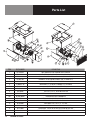
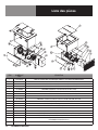
Parts List
ITEM PART NUMBER DESCRIPTION
1 RP CLP0102 HOLD DOWN CLIP COLD PANS AND PLATE CHILLERS
2 RP COV1703 COVER, REMOVABLE COND UNIT HOUSING, 9550,9552-290
3 RP DGH1701 DOGHOUSE, INNER PORTION, 9550&52-290 (T17-0049E-D14)
4 RP DGH1702 DOGHOUSE, OUTER PORTION, 9550&52-290 (T17-0049F-D17)
5 RP LVR0003 LOUVER, 14" X 26" DROP INS
6 EL WIR461-90 POWER CORD, 9' 16/3 W/90* PLUG000461-RT (SJTO WIRE)
7 EL WIR469A POWER CORD, 14/3 18" FEMALE
8 HD GRD1610 FAN GUARD, NICKEL CHROM FINISH , 116M RND
9 HD LID200 LID, 23.25" X 22.75", DLRS-200, 9552-290
10 RF CMP1606 COMPRESSOR, EMBRACO EM2X1121U, R290, 115V/60HZ
10a RF CMP1606SC COMPRESSOR START COMPONENTS
11 RP CNT1702 CONTROL, DANFOSS PRE-PROGRAMMED 9550/52-290
12 RF CNT1603 THERMISTOR, QTI, AIR SENSOR - BLACK, 10'
13 RF COI1606 COIL, COND. 3.46" X 9" X 5.9", 1/4" TUBE
14 RF FAN0601 FAN, AXIAL, 127MM X 38MM 120CFM, 115V CONDENSER
15 RF FLT9902 FILTER DRYER, 1/4x.042 FILTER, EKP-032 SC DBL INL CAP TUBE
16 RP CAP1702 WRAP, HEAT EXCHANGE, .026 X 13' CAP TUBE W/ 8' HEAT EXCHANGE
17 HD LID111 LID, 10.25" X 20.25" SLRS-111, 9550-290

OM-DROP-IN SERIES 15
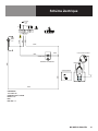
Electrical Schematic

16 OM-DROP-IN SERIES
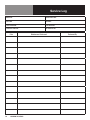
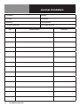
Service Log
Model No: Purchased From:
Serial No: Location:
Date Purchased: Date Installed:
Purchase Order No: For Service Call:
Date Maintenance Performed Performed By

OM-DROP-IN SERIES 17
Congratulations on your purchase of a Unified Brands Brand piece of equipment. Unified Brands believes strongly in the products it
builds and backs them with the best warranty in the industry. Standard with every unit is the peace of mind that this unit has been
thoroughly engineered, properly tested and manufactured to excruciating tolerances, by a manufacturer with over 30 years of industry
presence. On top of that front end commitment, Unified Brands has a dedicated staff of certified technicians that monitor our own
technical service hotline at 1-888-994-7636 to assist you with any questions or concerns that may arise after delivery of your new
Unified Brands equipment.
PARTS WARRANTY
1. One year parts replacement of any and all parts that are found defective in material or workmanship. Unified Brands warrants all
component parts of manufactured new equipment to be free of defects in material or workmanship, and that the equipment meets
or exceeds reasonable industry standards of performance for a period of one year from the date of shipment from any Unified
Brands factory, assembly plant or warehouse facility.
NOTE: warranties are effective from date of shipment, with a thirty day window to allow for shipment, installation and set-up. In
the event equipment was shipped to a site other than the final installation site, Unified Brands will warranty for a period of three
months following installation, with proof of starting date, up to a maximum of fifteen months from the date of purchase.
2. Free ground freight of customer specified location for all in warranty parts within continental U.S. Component part warranty does
not cover glass breakage or gasket replacement. Unified Brands covers all shipping cost related to component part warranty sent
at regular ground rates (UPS, USPS). Freight or postage incurred for any express or specialty methods of shipping are the
responsibility of the customer.
LABOR COVERAGE
In the unlikely event a Unified Brands manufactured unit fails due to defects in materials or workmanship within the first ninety days,
Unified Brands agrees to pay the contracted labor rate performed by an Authorized Service Agent (ASA). Any work performed by a
non-ASA will not be honored by Unified Brands. Please consult Unified Brands Technical Support (888-994-7636) for a complete listing
of ASAs or visit the service page of our website: www.unifiedbrands.net. Warranties are effective from date of shipment, with a thirty
day window to allow for shipment, installation and setup. Where equipment is shipped to any site other than final installation, Unified
Brands will honor the labor warranty for a period of ninety days following installation with proof of starting date, up to a maximum of
six months from date of purchase.
Temperature adjustments are not covered under warranty, due to the wide range of ambient conditions.
To request a warranty approval number, call our Field Service Department at: 1-888-994-7636
WHEN OPTIONAL 5 YEAR COMPRESSOR WARRANTY APPLIES
1. Provide reimbursement to an ASA for the cost of locally obtained replacement compressor in exchange for the return of the defective
compressor sent back freight prepaid. NOTE: Unified Brands does limit amount of reimbursement allowed and does require bill
from local supply house where compressor was obtained (customer should not pay servicing agent up front for compressor).
2. Provide repair at the manufacturing facility by requiring that the defective unit be sent back to Unified Brands freight prepaid.
Perform repair at the expense of Unified Brands and ship the item back to the customer freight collect.
3. Furnish a replacement compressor freight collect in exchange for the return of the defective compressor sent back freight prepaid.
4. Furnish complete condensing unit freight collect in exchange for the return of the defective condensing unit sent back freight
prepaid. (Decisions on whether or not to send complete condensing units will be made by Unified Brands in-house service
technician).
Warranty Policies

18 OM-DROP-IN SERIES
Warranty Policies
WHEN OPTIONAL LABOR EXTENSION POLICY APPLIES
Unified Brands will provide reimbursement of labor to an ASA for any customer that has an optional labor extension of our standard
warranty. (Contracted rates do apply) Unified Brands offers both 1 and 2 year extensions. Labor extensions begin at the end of our
standard warranty and extend out 9 months to 1 calendar year or 21 months to 2 calendar years from date of purchase. Please contact
Unified Brands technical service hotline at 1-888-994-7636 for details and any question on Authorized Service Agents (ASA).
WHEN EXPORT WARRANTIES APPLY
1. Unified Brands covers all non-electrical components under the same guidelines as our standard domestic policy.
2. All electrical components operated on 60Hz are covered under our standard domestic policy.
3. All electrical components operated on 50Hz are covered for 90 days from shipment only.
4. Service labor is covered for the first ninety days with authorization from the factory prior to service being performed.
5. Inbound costs on factory supplied items to be responsibility of the customer.
6. Extended warranty options are not available for parts, labor, or compressors from the factory.
ITEMS NOT COVERED UNDER WARRANTY
1. Maintenance type of repairs such as condenser cleaning, temperature adjustments, clogged drains, unit leveling and re-application
of silicone.
2. Unified Brands does not cover gaskets under warranty. Gaskets are a maintenance type component that are subject to daily wear and
tear and are the responsibility of the owner of the equipment. Because of the unlimited number of customer related circumstances
that can cause gasket failure all gasket replacement issues are considered non-warranty. Unified Brands recommends thorough
cleaning of gaskets on a weekly basis with a mild dish soap and warm water. With proper care Unified Brands gaskets can last up
to two years, at which time we recommend replacement of all gaskets on the equipment for the best possible performance.
NOTICE: FOOD LOSS IS NOT COVERED UNDER WARRANTY
3. Repairs caused by abuse such as broken glass, freight damage, or scratches and dents.
4. Electrical component failure due to water damage from cleaning procedures.
5. Improper installation of equipment.
6. Repairs performed outside of Unified Brands’ Authorized Service Agent network.
QUOTATIONS
Verbal quotations are provided for customer convenience only and are considered invalid in the absence of a written quotation. Written
quotations from Unified Brands are valid for 30 days from quote date unless otherwise specified. Unified Brands assumes no liability
for dealer quotations to end-users.
SPECIFICATION & PRODUCT DESIGN
Due to continued product improvement, specification and product design may change without notice.

OM-DROP-IN SERIES 19
SANITATION & SAFETY REQUIREMENTS
Product is designed to meet NSF sanitation and performance requirements, and UL safety requirements. Unified Brands is not
responsible for specific local requirements unless made aware of them prior to bid process. Additional costs may apply.
CANCELLATIONS
Orders canceled prior to production scheduling entered into engineering/production and cancelled are subject to a cancellation charge
(contact factory for details).
STORAGE CHARGES
Unified Brands makes every effort to consistently meet our customer’s shipment expectations. If after the equipment has been
fabricated, the customer requests delay in shipment, and warehousing is required:
1. Equipment held for shipment at purchasers request for a period of 30 days beyond original delivery date specified will be invoiced
and become immediately payable.
2. Equipment held beyond 30 days after the original delivery date specified will also include storage charges.
SHIPPING & DELIVERY
Unified Brands will attempt to comply with any shipping, routing or carrier request designated by dealer, but reserves the right to ship
merchandise via any responsible carrier at the time equipment is ready for shipment. Unified Brands will not be held responsible for
any carrier rate differences; rate differences are entirely between the carrier and purchaser. Point of shipping shall be determined by
Unified Brands (Weidman, MI/Prior, OK/Jackson, MS). At dealer’s request, Unified Brands will endeavor whenever practical to meet
dealer’s request. Freight charges to be collect unless otherwise noted.
DAMAGES
All crating conforms to general motor carrier specifications. To avoid concealed damage, we recommend inspection of every carton
upon receipt. In the event the item shows rough handling or visible damage to minimize liability, a full inspection is necessary upon
arrival. Appearance of damage will require removing the crate in the presence of the driver. A notation must be placed on the
freight bill and signed for by the truck driver at the time of delivery. Any and all freight damage that occurs to a Unified Brands
piece of equipment as a result of carrier handling is not considered under warranty, and is not covered under warranty guidelines. Any
freight damage incurred during shipping needs to have a freight claim filed by the receiver with the shipping carrier. Consignee is
responsible for filing of freight claims when a clear delivery receipt is signed. Claims for damages must be filed immediately (within 10
days) by the consignee with the freight carrier and all cartons and merchandise must be retained for inspection. Internal or concealed
damage may fall under Unified Brands responsibility dependent upon the circumstances surrounding each specific incident and are at
the discretion of the Unified Brands in-house service technician.
RETURNED GOODS
Authorization for return must first be obtained from Unified Brands before returning any merchandise. Any returned goods shipment
lacking the return authorization number will be refused, all additional freight costs to be borne by the returning party. Returned
equipment must be shipped in original carton, freight prepaid and received in good conditions. Any returned merchandise is subject
to a minimum handling charge (contact factory for details).
INSTALLATION
Equipment installation is the responsibility of the dealer and/or their customer.
Unified Brands requires all equipment to be professionally installed.
PENALTY CLAUSES
Dealer penalty clauses, on their purchase order or contractually agreed to between the dealer and their clients are not binding on
Unified Brands. Unified Brands does not accept orders subject to penalty clauses. This agreement supersedes any such clauses in
dealer purchase orders.
Warranty Policies

PART NUMBER PP MNL1702, REV D (08/17)
1055 Mendell Davis Drive • Jackson MS 39272
888-994-7636 • 601-372-3903 • Fax 888-864-7636
unifiedbrands.net
© 2017 Unified Brands. All Rights Reserved. Unified Brands is a wholly-owned subsidiary of Dover Corporation.
La page est en cours de chargement...
La page est en cours de chargement...
La page est en cours de chargement...
La page est en cours de chargement...
La page est en cours de chargement...
La page est en cours de chargement...
La page est en cours de chargement...
La page est en cours de chargement...
La page est en cours de chargement...
La page est en cours de chargement...
La page est en cours de chargement...
La page est en cours de chargement...
La page est en cours de chargement...
La page est en cours de chargement...
La page est en cours de chargement...
La page est en cours de chargement...
La page est en cours de chargement...
La page est en cours de chargement...
La page est en cours de chargement...
La page est en cours de chargement...
-
 1
1
-
 2
2
-
 3
3
-
 4
4
-
 5
5
-
 6
6
-
 7
7
-
 8
8
-
 9
9
-
 10
10
-
 11
11
-
 12
12
-
 13
13
-
 14
14
-
 15
15
-
 16
16
-
 17
17
-
 18
18
-
 19
19
-
 20
20
-
 21
21
-
 22
22
-
 23
23
-
 24
24
-
 25
25
-
 26
26
-
 27
27
-
 28
28
-
 29
29
-
 30
30
-
 31
31
-
 32
32
-
 33
33
-
 34
34
-
 35
35
-
 36
36
-
 37
37
-
 38
38
-
 39
39
-
 40
40


