DOC023.97.80464
2200 PCX
04/2018, Edition 2
Basic User Manual
Manuel d'utilisation de base

English..............................................................................................................................3
Français......................................................................................................................... 25
2

Table of contents
Specifications on page 3 Operation on page 17
General information on page 4 Maintenance on page 20
Installation on page 7 Troubleshooting on page 24
Startup on page 16
Expanded manual version
For additional information, refer to the expanded version of this manual, which is available on the
manufacturer's website.
Specifications
Specifications are subject to change without notice.
Specification Details
Dimensions (W x D x H) 350 x 211 x 178 mm (13.8 x 8.3 x 7.0 in.)
Weight 4.89 kg (10.78 Ibs)
Operating temperature 0 to 50 °C (32 to 122 °F); maximum relative humidity 80% for temperatures
with a maximum of 31 ºC (87.8 °F) decreasing linearly to 50% relative
humidity at 40 ºC (104 °F)
Storage temperature 0 to 50 °C (32 to 122 °F)
Enclosure NEMA 4X (indoor use)
Fittings Quick-connect. Connect to ¼-inch O.D tubing
Power requirements 115-240 VAC, 50/60 Hz, 1A
Maximum solution pressure 65 psig, not more than 1 minute duration; 55 psig continuous
Flow rate 100 mL/minute nominal
Particle size Smallest size: 2 µm
Largest size: 750 µm
Indicators Power, counting display, cleaning sensor and alarm
Distance from computer to sensor 1219.20 m (4000 ft.) maximum, entire RS485 signal path
Flow control (optional) Passive control devices available to control water flow through the
instrument
Digital communication Modbus ASCII; WQS Vista data collection software (optional): Monitor filter
performance and make reports. Refer to the software documentation for
computer requirements.
Hach UDG1000 software (optional) Organize instrument readings on a SCADA system
Analog input/output card (optional) Input: accepts input signals from external devices
Output: supplies an analog output level proportional to total number of
particles counted (raw count)
Pollution degree 2
Installation category I
Protection class III (supplied by SELV power source)
English 3

Specification Details
Certifications UL/CSA approved 100 to 115 V, 50/60 Hz external wall-type power supply;
wall plug-in power supply is not NEMA rated
Warranty 1 year
General information
In no event will the manufacturer be liable for direct, indirect, special, incidental or consequential
damages resulting from any defect or omission in this manual. The manufacturer reserves the right to
make changes in this manual and the products it describes at any time, without notice or obligation.
Revised editions are found on the manufacturer’s website.
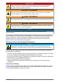
Safety information
N O T I C E
The manufacturer is not responsible for any damages due to misapplication or misuse of this product including,
without limitation, direct, incidental and consequential damages, and disclaims such damages to the full extent
permitted under applicable law. The user is solely responsible to identify critical application risks and install
appropriate mechanisms to protect processes during a possible equipment malfunction.
Please read this entire manual before unpacking, setting up or operating this equipment. Pay
attention to all danger and caution statements. Failure to do so could result in serious injury to the
operator or damage to the equipment.
Make sure that the protection provided by this equipment is not impaired. Do not use or install this
equipment in any manner other than that specified in this manual.
Use of hazard information
D A N G E R
Indicates a potentially or imminently hazardous situation which, if not avoided, will result in death or serious injury.
W A R N I N G
Indicates a potentially or imminently hazardous situation which, if not avoided, could result in death or serious
injury.
C A U T I O N
Indicates a potentially hazardous situation that may result in minor or moderate injury.
N O T I C E
Indicates a situation which, if not avoided, may cause damage to the instrument. Information that requires special
emphasis.
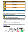
Precautionary labels
Read all labels and tags attached to the instrument. Personal injury or damage to the instrument
could occur if not observed. A symbol on the instrument is referenced in the manual with a
precautionary statement.
Electrical equipment marked with this symbol may not be disposed of in European domestic or public
disposal systems. Return old or end-of-life equipment to the manufacturer for disposal at no charge to
the user.
This symbol, if noted on the instrument, references the instruction manual for operation and/or safety
information.
4 English

This symbol indicates that a risk of electrical shock and/or electrocution exists.
This symbol indicates a laser device is used in the equipment.
This symbol indicates the presence of devices sensitive to Electro-static Discharge (ESD) and
indicates that care must be taken to prevent damage with the equipment.
Certification
Canadian Radio Interference-Causing Equipment Regulation, IECS-003, Class A:
Supporting test records reside with the manufacturer.
This Class A digital apparatus meets all requirements of the Canadian Interference-Causing
Equipment Regulations.
Cet appareil numérique de classe A répond à toutes les exigences de la réglementation canadienne
sur les équipements provoquant des interférences.
FCC Part 15, Class "A" Limits
Supporting test records reside with the manufacturer. The device complies with Part 15 of the FCC
Rules. Operation is subject to the following conditions:
1. The equipment may not cause harmful interference.
2. The equipment must accept any interference received, including interference that may cause
undesired operation.
Changes or modifications to this equipment not expressly approved by the party responsible for
compliance could void the user's authority to operate the equipment. This equipment has been tested
and found to comply with the limits for a Class A digital device, pursuant to Part 15 of the FCC rules.
These limits are designed to provide reasonable protection against harmful interference when the
equipment is operated in a commercial environment. This equipment generates, uses and can
radiate radio frequency energy and, if not installed and used in accordance with the instruction
manual, may cause harmful interference to radio communications. Operation of this equipment in a
residential area is likely to cause harmful interference, in which case the user will be required to
correct the interference at their expense. The following techniques can be used to reduce
interference problems:
1. Disconnect the equipment from its power source to verify that it is or is not the source of the
interference.
2. If the equipment is connected to the same outlet as the device experiencing interference, connect
the equipment to a different outlet.
3. Move the equipment away from the device receiving the interference.
4. Reposition the receiving antenna for the device receiving the interference.
5. Try combinations of the above.
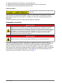
Class 1 laser
This symbol indicates that the instrument is a Class
1 LASER product.
This product complies with IEC/EN 60825-1:2007 and 21 CFR 1040.10 except for deviations
pursuant to Laser Notice No. 50, dated June 24, 2007. FDA accession number: 8921784-11.
This product contains a laser that is not user-serviceable.
English
5

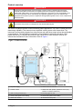
Product overview
D A N G E R
Chemical or biological hazards. If this instrument is used to monitor a treatment process and/or
chemical feed system for which there are regulatory limits and monitoring requirements related to
public health, public safety, food or beverage manufacture or processing, it is the responsibility of the
user of this instrument to know and abide by any applicable regulation and to have sufficient and
appropriate mechanisms in place for compliance with applicable regulations in the event of malfunction
of the instrument.
D A N G E R
Fire hazard. This product is not designed for use with flammable liquids.
The 2200 PCX particle counter is used for drinking water applications. The 2200 PCX does not have
data storage capability. The instrument uses a particle counting sensor with a laser-diode. The
instrument converts analog signals from other devices and send those output values through Modbus
communications. The instrument is used with the Vista software to select the size range, count
period and flow rate. Complete data collection with Hach UDG or Vista software. Refer to the
software documentation for more information. Refer to Figure 1.
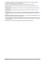
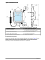
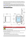
Figure 1 Product overview
1 AC power supply 6 Water weir flow controller
2 Particle counter 7 Water weir drain junction (mounted 1.22 m (4 ft)
below the maximum head loss)
3 Wall mounting brackets (4x) 8 Mounting clips for weir
4 Sensor outlet quick-connect fitting 9 Sensor inlet quick-connect fitting
5 Water weir overflow 10 Electrical access ports
6 English

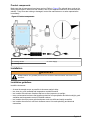
Product components
Make sure that all components have been received. Refer to Figure 2For optional items such as the
analog input/output kit, water weir and software, refer to the expanded manual on the manufacturer's
website.. If any items are missing or damaged, contact the manufacturer or a sales representative
immediately.
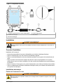
Figure 2 Product components
1 Particle counter with power cord 4 Power cord
2 Cleaning solution 5 Power supply
3 Cleaning brush
Installation
W A R N I N G
Multiple hazards. Only qualified personnel must conduct the tasks described in this section of the
document.
Installation guidelines
Install the instrument:
• As near the sample source as possible to decrease analysis delay
• In a clean, dry, well ventilated and temperature controlled location
• In a location with minimum vibrations that has no direct exposure to sunlight
• In an environmental enclosure that supplies protection from precipitation and direct sunlight, good
ventilation and temperature control if installed outdoors
• In a location where the power switch and power cord are visible and easily accessible
• In a location where there is sufficient clearance around it to make plumbing and electrical
connections
English
7

Mechanical installation
Attach the instrument to the wall
W A R N I N G
Personal injury hazard. Make sure that the wall mounting is able to hold 4 times the weight of the
equipment.
This instrument is rated for an altitude of 2000 m (6562 ft) maximum. Use of this instrument at an
altitude higher than 2000 m can slightly increase the potential for the electrical insulation to break
down, which can result in an electric shock hazard. The manufacturer recommends that users with
concerns contact technical support.
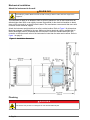
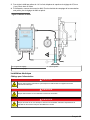
Attach the instrument upright and level on a flat, vertical surface. Refer to Figure 3 for dimensions.
Mounting hardware is supplied by the user. Make sure that an electrical outlet is available that is
above flood stage areas. If purchased with the instrument, install the standard water weir flow
controller so that the sensor outlet of the instrument is lower than the water weir overflow. Refer to
Figure 1 on page 6.
Figure 3 Installation dimensions
Plumbing
D A N G E R
Fire hazard. This product is not designed for use with flammable liquids.
8 English

Sample line guidelines
Select a good, representative sampling point for the best instrument performance. The sample must
be representative of the entire system.
To prevent erratic readings:
• Collect samples from locations that are sufficiently distant from points of chemical additions to the
process stream.
• Make sure that the samples are sufficiently mixed.
• Make sure that all chemical reactions are complete.
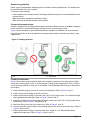
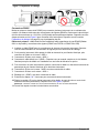
Connect the sample stream
Install the sample line into a larger process pipe to minimize interference from air bubbles or pipeline
bottom sediment. A sample line that goes into the center of a process pipe is best.
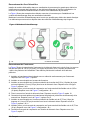
Figure 4 shows examples of good and bad methods of sample line installation into a process pipe.
Keep the sample line as short as possible to decrease analysis delay. Sediment can collect in long
sample lines.
Figure 4 Sampling methods
1 Air 2 Sample flow
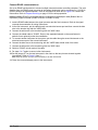
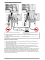
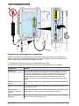
Plumb the instrument
Figure 5 shows the instrument and the water weir controller connection to the water system. Make
sure that the tubing length is 3.05 m (10 ft) maximum. Tubing lengths longer than 3.05 m (10 ft) will
cause the larger particles to "drop out" of the sample. This will decrease the accuracy of the particle
size reading.
1. Install a plumbing tap with a shut-off valve for the instrument. Refer to Figure 5, item 5.
2. Install a quick-connect fitting on the shut-off valve.
3. Install a quick-connect fitting to one end of the 3.05 m (10 ft) length of the 1/4-in. black semi-rigid
tubing supplied with water weir. Refer to Figure 5, items 2 and 8.
4. Install the nut and then the compression fitting to the other end of the 3.05 m (10 ft) length of the
black tubing. Refer to Figure 5, configuration "B".
5. Attach the fitting to the inlet on the water weir. Refer to Figure 5, item 10.
6. Connect the quick-connect fitting to the plumbing tap (shut-off valve) of the water source. Refer to
Figure 5, items 2 and 5.
7. Install a quick-connect fitting to one end of the 18-in. length of 1/4 in. black flexible tubing
supplied with water weir. Refer to Figure 5, items 2 and 11.
English
9

8. Install the nut and then the compression fitting to the other end of 18-in. length of the black
flexible tubing. Refer to Figure 5, configuration "B".
9. Connect the compression fitting to the water weir outlet. Refer to Figure 5, item 7.
10. Connect the quick-connect fitting to the sensor inlet port of the instrument. Refer to Figure 5,
items 2 and 12.
11. Attach the quick-connect fitting to a 12-in. length of ¼-in. black flexible tubing. Refer to Figure 5,
items 2 and 3.
12. Attach the quick-connect fitting to the sensor outlet port on the instrument. Refer to Figure 5,
items 1 and 2.
13. Put the other end of the 12-in. length of ¼-in. black flexible tubing into the hole of the adjustment
cap. Make sure that the end of the tubing is 6.4 mm (0.25 in.) inside the cap. Refer to Figure 5,
item 4.
14. Install the drain line on the water weir. Install a clear ½-in. I.D. hose over the barbed fitting on the
water weir drain. Refer to Figure 5, items 6 and 9.
15. Use the drain hose to measure the distance between the water weir drain and the nearest waste
drain. Remove the excess length of the drain hose. Install the other end of the hose on the drain.
Refer to Figure 5.
16. Open the shut-off valve on the plumbing tap and examine the tubing for leaks.
10 English

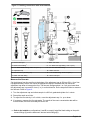
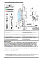
Figure 5 Plumbing connections with measurements
1 Sensor outlet port 7 Water weir outlet
2 Quick-connect fitting
1
8 ¼ in. black semi-rigid tubing, 3.05 m (10 ft)
3 ¼ in. black flexible tubing, 308.4 mm (12 in.) 9 ½ in. I.D. clear drain tubing
4 Adjustment cap 10 Water weir inlet
5 Shut-off valve in plumbing tap 11 ¼ in. flexible tubing, 45.72 cm (18 in.)
6 Water weir drain fitting 12 Sensor inlet port
Measure the flow rate
Set the distance from the overflow to the bottom of the adjustment cap to 832 mm (33 in.) for a flow
rate approximately 100-mL/min. Move the adjustment cap up to decrease the flow. Move the
adjustment cap down to increase the flow. The flow rate changes about 1 or 2 mL per minute when
the adjustment cap is moved 25.4 mm (1 in.) in vertical direction. Do the steps that follow to measure
the flow rate. Refer to Figure 6.
1. Turn the adjustment cap and collect sample in a 200-mL graduated cylinder for 1 minute.
2. Record the result as mL/min.
3. To adjust the flow rate by 1 to 2 mL/min, move the adjustment cap 1 in. up or down.
4. If necessary, measure the flow rate again. The results of the count concentration data will be
more accurate, the more accurately the flow is set.
1
Refer to the installation configurations A and B to correctly install the black tubing on the quick-
connect fittings (A) and the water weir inlet and outlet fittings (B).
English 11

Figure 6 Flow rate measurement
1 Adjustment length 3 Graduated cylinder
2 Adjustment cap
Electrical installation
Wiring for power
D A N G E R
Electrocution hazard. Always remove power to the instrument before making electrical connections.
D A N G E R
Electrocution hazard. Protective Earth Ground (PE) connection is required.
D A N G E R
Electrical shock and fire hazards. Make sure to identify the local disconnect clearly for the conduit
installation.
D A N G E R
Electrocution hazard. If this equipment is used outdoors or in potentially wet locations, a Ground Fault
Circuit Interrupt (GFCI/GFI) device must be used for connecting the equipment to its main power
source.
12 English

W A R N I N G
Electrical shock and fire hazards. Make sure that the user-supplied power cord and non‐locking plug
meet the applicable country code requirements.
W A R N I N G
Electrocution hazard. Make sure that there is easy access to the local power disconnect.
W A R N I N G
Electrical shock hazard. Externally connected equipment must have an applicable country safety
standard assessment.
N O T I C E
Install the cover after all the connections are made to keep the environmental enclosure rating.
The electrical connections to power the instrument are made at the factory. Make sure to use an
electrical outlet that is above flood stage areas. It is necessary to set the power to off and then to on
for some programming functions. When all of the connections are made, connect the power cord to
an electrical outlet.. Refer to Connect the power cord on page 16.
Electrostatic discharge (ESD) considerations
N O T I C E
Potential Instrument Damage. Delicate internal electronic components can be damaged by static
electricity, resulting in degraded performance or eventual failure.
Refer to the steps in this procedure to prevent ESD damage to the instrument:
• Touch an earth-grounded metal surface such as the chassis of an instrument, a metal conduit or
pipe to discharge static electricity from the body.
• Avoid excessive movement. Transport static-sensitive components in anti-static containers or
packages.
• Wear a wrist strap connected by a wire to earth ground.
• Work in a static-safe area with anti-static floor pads and work bench pads.
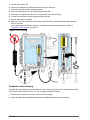
Prepare the wiring
Figure 7 shows the wire connection to the terminal blocks. Remove the wire insulation by 6.35 mm
(0.25 in.) before the installation. Make sure that the wire is fully installed in the connector so that no
bare wire shows.
Figure 7 Wiring preparation
English 13

Connect RS485 communications
Set up an RS485 serial network to connect multiple instruments and a controlling computer. The total
distance from the RS485 signal converter to the farthest instrument can be a maximum of 1219.20 m
(4000 ft) without an amplifier/repeater. Refer to the steps that follow and to Figure 8 to connect two
instruments. Refer to Prepare the wiring on page 13 for the wire preparation.
Items to collect: RS485-type shielded and a low capacitance twisted-pair cable (Belden 9841 or
equivalent), signal converter (RS485 to RS232 or RS485 to USB)
1. Install a RS485 cable between the signal converter and the first instrument. Refer to the signal
converter documentation for wiring instructions.
2. At the first instrument, put the cable through one electrical access port and then connect the blue
wire to the terminal lug with the "485B" label.
3. Connect the white wire to the terminal lug with the "485A" label.
4. Connect the shield cable to "SGND". Refer to the expanded manual on the manufacturer's
website for an optional junction box installation.
5. To connect another instrument to the system, put the cable through a second instrument to the
electrical access port of the second instrument.
6. Connect the blue wire to the terminal lug with the "485B" label at both ends of the cable.
7. Connect the white wire to the terminal lug with the "485A" label.
8. Shield to "SGND" at both ends of the cable.
9. Do steps 2 to 7 again to connect other instruments.
10. Set the jumper JP1 on the last instrument in the chain so that two pins are shorted together
(terminated). Refer to Figure 8, item 3.
Note: Keep the jumper JP1 open (not terminated) on all other instruments.
11. Close the covers and apply power to the instruments.
14 English

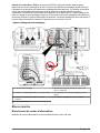
Figure 8 Particle counters wiring
1 Wiring for multiple instrument systems 4 RS485 signal converter with cable to computer
2 Wiring for last instrument in multiple instrument
system
5 RS485 shielded cable (Beldon 9841 or equivalent)
3 Terminated JP1 jumper configuration for last
instrument
6 Open JP1 jumper configuration
Select the voltage inputs
1. Select +5 V full scale and remove jumpers JP2 through JP7 that are the same as the inputs used
(AIN2 through AIN7).
2. Select +10 V full scale and install jumpers JP2 through JP7 that are the same as the inputs used
(AIN2 through AIN7).
3. Configure the voltage inputs to accept 4–20 mA inputs when connected to a 250 ohm or a 1% (or
better) shunt resistor in parallel with the analog signal cable. Set the applicable jumper for a 5 V
operation.
4–20 mA current inputs: Use IN0 (RET0 is ground) and IN1 (RET1 is ground) on the instrument
interconnect card. The incoming data is sent along with the particle count data via serial
communications to the computer. With the installed online software, the data is shown and recorded.
Refer to the expanded manual on the manufacturer's website for more information.
4–20 mA current outputs: If the optional I/O kit is installed, each sensor has eight 4–20 mA analog
outputs of particle count data that the user can configure to output raw particle counts. The 4–20 mA
output levels are in relation to the total number of particles counted during the sample period. The
data is shown and recorded in the installed PC software. Each size category will have a unique
analog output signal and will connect to an individual analog input on the data acquisition system
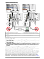
input terminals. Analog outputs are connected to the instrument interconnect card. Refer to Figure 9.
English
15

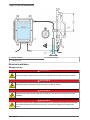
Figure 9 Analog output wiring
1 Analog input card 5 Optional external loop power, 15-24 VDC (150 mA)
2 Jumper position (internal loop power) 6 Wires from analog output terminals (OUT0-OUT7)
3 Jumper position (external loop power) 7 Analog connections on PLC, SCADA
4 Interconnect card
Startup
Connect the power cord
Connect the power cord to an electrical outlet with protective earth ground.
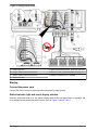
Status indicator light and count display window
When the instrument is set to on, the status indicator lights on the front panel show. In operation, the
count display window shows the particle count. Refer to Figure 10 and to Table 1.
16
English

Figure 10 Front panel description
1 Counting LED 4 Clean sensor LED
2 Power LED 5 Count display window
3 Alarm LED
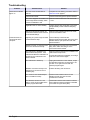
Table 1 Status indicators
Indicator Description
Counting LED Comes on during the count cycle.
Power LED Comes on when the instrument power is set to on.
Alarm LED Comes on when the alarm limit is exceeded.
Clean sensor LED Comes on if a sensor defect is identified. Refer to Clean the cell on page 21 and/or
Troubleshooting on page 24.
Count display window Shows the "normalized" particle count (counts/mL) in the size range limits for the count
period. If the flow rate is set to 0 in the configuration menu, the display shows the raw
counts of the selected sizes (count/count period). The raw count is configured with the
WQS Vista Software.
Operation
Configuration
D A N G E R
Electrocution hazard. Always remove power to the instrument before making electrical connections.
Most applications can use the factory configuration. Refer to Configure the RS485 connection
on page 17 for a custom configuration for an RS485 operation. Refer to the expanded manual on
the manufacturer's website for a custom configuration for an RS232 operation.
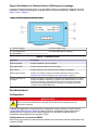
Configure the RS485 connection
Make sure that all connections are made to the instrument before the RS485 configuration.
1. Find the file "Advanced CRTS" on the manufacturer's website to download. Save the file from the
website to the computer.
2. Make sure that the instrument power is set to on and is connected to the computer.
3. Unzip the advanced "CRTS_2200 PCX" configuration file. Push Run to start the
"AdvancedCRTS.exe" file to install CRTS.
4. Open "CRTS".
5. Go to "Setup PCX" to make sure that the communications operate correctly.
English
17

6. Close the setup screen and go to the terminal.
Note: Make sure that only one instrument is connected during the setup.
7. Make sure that the correct COM port is selected.
8. Click on "Send Lead Command". Do not confirm with OK.
9. Set the instrument power to off. Wait 2 seconds and set the instrument to on again.
10. Confirm "Load Delay: 2 Sec." within 30 seconds.
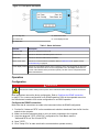
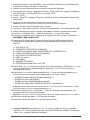
11. When the "load" command was sent successfully, the menu that follows shows: ---MAIN MENU---
RMCA [2082375-1E]
12. Type the number 1 to 9 and do the prompts at the command line that follow to select a specific
operating parameter. Refer to Table 2.
1. UNIT ID32 [0...32
2
]
2. COUNT PERIOD00:10 [MIN,SEC]
3. CAL LIMITS0800–1200 [LOWER, UPPER mV]
4. COUNT MODEMANUAL [AUTO, MANUAL]
5. PANEL DISPLAY2.0 [CUMULATIVE 9U0]
6. FLOW RATE 100 mL/min]
7. CALIBRATE
8. DEFAULT MEMORY
9. SETUP ANALOG I/OQ = QUIT
13. Select "9" to configure the analog inputs and outputs. Select "1" to set the analog inputs to on or
off. Push "2" to go out of the output configuration menu.
14. Select "1" for analog inputs or "2" for analog outputs, then enter the command number but do not
push the <Enter> key.
• ENTER ANALOG OUTPUT CHANNEL [0 to 7]
• ENTER LOWER SIZE
• ENTER UPPER SIZE (0=cumulative)
• ENTER FULL SCALE COUNT (0=disable channel)
Note: Enter the lowest particle size and 0 for no upper limit. The upper size specifies the count value shown by
20 mA.
15. Complete the sequence with “Q <Enter>”. All of the configuration information is saved in the
instrument memory.
Note: To go out of the configuration menu at the very end, stop the sequence with “P <Enter>”.
16. Do steps 11 to 15 again for more channels.
17. Do steps 2 to 11 again for more instruments.
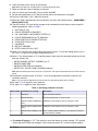
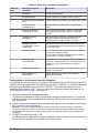
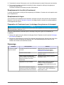
Table 2 Operating parameter selection
Menu number Command line message Description
1 ENTER ID Enter the Modbus address.
2 ENTER MIN:SEC Set count period when in "AUTO" mode.
3 ENTER LOWER THRESHOLD
(mV)
Calibration check threshold. Do not change the value.
ENTER UPPER THRESHOLD
(mV)
Calibration check threshold. Do not change the value.
4 ENTER COUNT MODE (A OR
M)
Auto = locally self-timed; Manual = count period is controlled
by data collection software.
2
The default ID number is "32". This number is set at the factory to a lower number. "32" typically
shows that the EPROM was changed. If the instrument shows "32", contact technical support.
18 English

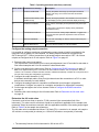
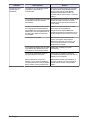
Table 2 Operating parameter selection (continued)
Menu number Command line message Description
5 ENTER LOWER SIZE Specify the particle size range (for front panel numerical
display units only). Do not set a lower size to less than
2 microns.
ENTER UPPER SIZE (0 FOR
CUMULATIVE)
Specify the largest particle to be included in the count shown
on the display (for front panel numerical display units only).
6 ENTER FLOW RATE If 0 is entered, the display shows particles/count period (raw
count).
If 100 mL/min is entered, the display shows particles/mL
(normalized count).
7 CALIBRATING DISPLAY Use for the 4-20 mA analog output calibration. Toggles from
4-20 mA when the space bar is pushed on the connected
computer.
8 DEFAULT MEMORY Do not enter a message on this line unless instructed by the
manufacturer.
9 SETUP ANALOG I/O Use only when an analog I/O card is installed.
Configure the analog output connection
It is possible to configure a maximum of eight analog output signals of particle count data for the
instrument with an analog I/O card installed. The analog output connections are identified as
OUT0 through OUT7. Ground connections for all analog outputs are made to I-RET. All of these
outputs are configured as 4–20 mA outputs. Refer to Figure 9 on page 16.
1. Determine the correct count period.
The manufacturer recommends to set a count period between 6 and 15 seconds for raw water or
filter influent samples and 24 to 60 seconds for clean filtered water.
2. Set the count period in the main menu. Refer to Configure the RS485 connection on page 17.
Note: If the digital RS485 signal is connected to the data collection software, the count period is set in the
software. The connection to WQS Vista data collection software automatically overrides the count period set in
the main menu during the configuration programming.
3. Configure the output channels (1 to 8).
A shielded, twisted-pair cable, wiring for eight channels and the connections to a PLC or other
devices are necessary for each channel.
4. Configure the analog outputs for cumulative or differential count formats in all possible
combinations. Configure one output for cumulative and another for differential if necessary.
5. Set the lower and upper size for one channel. Refer to Configure the RS485 connection
on page 17.
6. Determine the correct setting for the full scale value. Refer to Determine the full scale value
on page 19.
Determine the full scale value
Counts/mL must be less than or equal to 17,000 counts/mL (the concentration limit of the
instrument). The value used for counts/mL should be as small as is applicable for the sample to be
measured. Select the maximum counts/mL with the applicable resolution of the analog output signal.
Refer to Table 3 for the sample size references.
The full scale value is calculated as follows: Full Scale (FS) = counts/mL x mL sample; mL sample =
100 mL/min
3
x count period (in minutes) or = 100 mL/60 seconds x count period (in seconds)
3
The necessary flow rate for this instrument is 100 mL/min ± 5%.
English 19

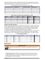
Determine the full scale value with the estimate of the maximum cumulative particle counts at the
sensitivity of the instrument, >2 μm. When the value is determined, calculate the estimated full scale
value for other channels with the applicable divisor. Refer to Table 4.
4
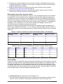
Table 3 Sample size reference table (flow = 100 mL/min)
Count Period (seconds) Sample Size (mL) Count Period (seconds) Sample Size (mL)
6 10 24 40
12 20 30 50
15 25 48 80
18 30 60 100
Table 4 Divisors for full scale value determination (> 2µm)
Channel Divisor Channel Divisor Channel Divisor
>3µ 3.4 >7µ 43 >11µ 166
>4µ 8 >8µ 64 >12µ 216
>5µ 15.6 >9µ 90 >14µ 343
>6µ 27 >10µ 125 >15µ 422
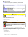
Complete a SCADA calculation
When the values are specified after each analog output for the lower limit, the upper limit and the full
scale, the SCADA programmer enters the values for: The channel range, the upper size limit and the
full scale value. The lower limit (4 mA) will always be 0 counts. In all cases, the lower limit signal
(4 mA) will be 0 (zero) particles, the upper limit signal (20 mA) will be equal to the full scale value.
The full scale value must then be divided by the sample volume (mL sample).
For example: If the sample flow rate is 100 mL/min, a count period of 30 seconds, the sample volume
result is 50 mL. The maximum expected particle count is 1000 particles/mL. Then, the FS value =
1000 particles/mL x 50 mL = 50,000 CH0 set to cumulative particle counts > 2 μm. Refer to Table 5.
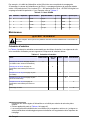
Table 5 SCADA calculation
CH Lower Upper Full scale Label at SCADA 4 mA = 20 mA = Divide by
5
0 2 0 5000 >2 μm 0 5000 50
1 5 0 3200
6
>5 μm 0 3200 50
2 7 0 1166
2
>7 μm 0 1166 50
3 10 0 400
2
>10 μm 0 400 50
Maintenance
W A R N I N G
Multiple hazards. Only qualified personnel must conduct the tasks described in this section of the
document.
4
To make an estimate for the divisors of the values that are not shown in the table, use the
formula that follows: Divisor = (Size/2)
3
. For example, the divisor for >18 μm is (18/2)
3
= 729
5
Divide by the value that value equals the mL sample used to calculate the full scale value.
6
Divisor applied from Table 4 on page 20
20 English
La page est en cours de chargement...
La page est en cours de chargement...
La page est en cours de chargement...
La page est en cours de chargement...
La page est en cours de chargement...
La page est en cours de chargement...
La page est en cours de chargement...
La page est en cours de chargement...
La page est en cours de chargement...
La page est en cours de chargement...
La page est en cours de chargement...
La page est en cours de chargement...
La page est en cours de chargement...
La page est en cours de chargement...
La page est en cours de chargement...
La page est en cours de chargement...
La page est en cours de chargement...
La page est en cours de chargement...
La page est en cours de chargement...
La page est en cours de chargement...
La page est en cours de chargement...
La page est en cours de chargement...
La page est en cours de chargement...
La page est en cours de chargement...
La page est en cours de chargement...
La page est en cours de chargement...
La page est en cours de chargement...
La page est en cours de chargement...
La page est en cours de chargement...
La page est en cours de chargement...
-
 1
1
-
 2
2
-
 3
3
-
 4
4
-
 5
5
-
 6
6
-
 7
7
-
 8
8
-
 9
9
-
 10
10
-
 11
11
-
 12
12
-
 13
13
-
 14
14
-
 15
15
-
 16
16
-
 17
17
-
 18
18
-
 19
19
-
 20
20
-
 21
21
-
 22
22
-
 23
23
-
 24
24
-
 25
25
-
 26
26
-
 27
27
-
 28
28
-
 29
29
-
 30
30
-
 31
31
-
 32
32
-
 33
33
-
 34
34
-
 35
35
-
 36
36
-
 37
37
-
 38
38
-
 39
39
-
 40
40
-
 41
41
-
 42
42
-
 43
43
-
 44
44
-
 45
45
-
 46
46
-
 47
47
-
 48
48
-
 49
49
-
 50
50


dans d''autres langues
- English: Hach 2200 PCX
Documents connexes
-
 Hach MET ONE 6015 Manuel utilisateur
-
 Hach HIAC ROC Manuel utilisateur
-
 Hach Polymetron 9523 Basic User Manual
-
 Hach 9586sc Basic User Manual
-
 Hach A1000 Basic User Manual
-
 Hach WDMP sc Manuel utilisateur
-
 Hach AS950 AWRS Basic Installation And Maintenance
-
 Hach Lange astroTOC Basic User Manual
-
 Hach MET ONE 3423 Basic User Manual
-
 Hach Polymetron 9523sc pH Basic User Manual