SportsArt A966 Le manuel du propriétaire
- Taper
- Le manuel du propriétaire

A966 OWNER’S MANUAL CONTENTS
1. INTRODUCTION ................................................................................ 2
2. SAFETY PRECAUTIONS .................................................................. 3
3. LIST OF PARTS ................................................................................. 4
4. ASSEMBLE THE PRODUCT ............................................................. 7
STEP 1 Install Frames and Connectors ................................................. 7
STEP 2 Install the Weight Plate Pegs .................................................... 10
STEP 3 Secure the Product ................................................................... 11
STEP 4 Level the Product ...................................................................... 12
STEP 5 Unit Inspection .......................................................................... 13
5. OPERATE THE PRODUCT ............................................................... 14
OPERATION Operate the Product ........................................................ 14
OPERATION Exercising Instructions ..................................................... 16
6. MAINTENANCE ................................................................................ 20
MAINTENANCE Safety Precautions ................................................... 20
MAINTENANCE Schedule .................................................................... 21
MAINTENANCE Task List .................................................................... 22
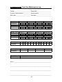
MAINTENANCE One-Year Maintenance Log ....................................... 23
7. CONSIGNES DE SÉCURITÉ IMPORTANTES ................................. 24
8. APPENDIXES ................................................................................... 25
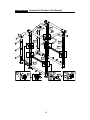
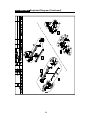
APPENDIXES Exploded Diagram ........................................................ 25

2
1. INTRODUCTION
Congratulations on the purchase of a high quality SportsArt product, the A966
Power Cage. Constructed of high quality materials and designed for years of reliable
performance, this product was made for full commercial use.
Before this product is assembled or operated, we recommend that you familiarize
yourself with this manual. Understanding the correct assembly and operation of
this product will help ensure that exercisers obtain their tness goals safely and
successfully.
R
L

3
2. SAFETY PRECAUTIONS
This product was designed and built for optimum safety. However certain precau-
tions apply during the use of this product. Please note the following safety
precautions:
• Please read the entire manual before assembly and operation. Make sure the
product is installed and operated as instructed in this manual.
• Assemble and operate the product on a solid, level surface. Do not use outdoors
or near water, including pools and saunas.
• Check the product before every use. Make sure all parts are assembled, and all
fasteners are tightened. Do not use the product if it is disassembled in any way.
• Wear proper workout clothing. Do not wear loose clothing. Do not wear shoes
with leather soles or high heels. Tie all long hair back. Do not go barefoot on this
product.
• Keep away from moving parts. Moving parts may or may not stop immediately if
an object becomes caught or impedes normal motion.
• Use this product only for its intended purpose as described in this manual.
• Be careful when mounting and dismounting the unit.
• Never operate this product if it has been damaged in any way. If it is not work-
ing properly, or has been dropped or damaged, contact a service technician for
repairs.
• Do not use accessories or parts that are not specifically recommended by the
manufacturer (SportsArt) . Such parts might cause injuries or cause the unit to
fail and void the warranty. We will not be responsible for any safety issue that
arises due to the misuse of accessories or parts. At the same time, we will termi-
nate the warranty terms of this equipment.
• This product is not intended for use by persons (including children 12 or younger)
with reduced physical, sensory, or mental capabilities, or by people who are
otherwise deficient in product knowledge or experience. If such people use this
product, they should be given training and be supervised at all times by some-
one responsible for their safety.
• Children 12 or younger should be supervised to ensure that they do not play on
or near the product.
• The user weight limit for this product is 227 kg, 500 lb.
• Maintenance and repair must be performed by trained service personnel
only. Improper maintenance would not only damage the machine, but
also may present a danger to the exerciser.
• Warning that any of the adjustment devices that could interfere with the
user’s movement should not be left projecting.
• Over exercise may result in serious injury or death.
CAUTION: If you feel any pain or any abnormal sensations, STOP YOUR WORK-
OUT and consult your physician immediately. Work within your recommended ex-
ercise level. DO NOT work to exhaustion. Before beginning any exercise program,
you should consult with your doctor. It is recommended that you undergo a complete
physical examination.

4
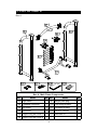
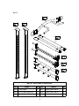
3. LIST OF PARTS
Box A
Box A - Main Frame Components
No. Name Qty. No. Name Qty.
A1 Right frame 1 A7 Weight plate peg 8
A2 U-shaped connector 1 A16 Floor xing bracket 2
A3 Left frame 1 A17 U-shaped bracket 2
A4 Connector 1 A18 Owner’s manual 1
A5 Weight lifting bar hook A 1 A19 Hardware kit 1
A6 Weight lifting bar hook B 1

5
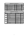
Box B
Box B - User Frame Components
No. Name Qty. No. Name Qty.
A10 Front frame 2 A13 Safety catch bar A 1
A11 Pull up bar connector 1 A14 Safety catch bar B 1
A12 Upper connector 2 A15 Lower connector 2

6
Components on the Product
No. Name Specication Notes
31
Washer D16*d10.2*t1.0
Hex nylon nut M10
32
Hex nylon nut M10
Spring washer M10
Washer D19*d10.2*t3
33
Hex head screw M10*P1.5*L150
Spring washer M10
Washer D19*d10.2*t3
55
Washer D20*d7*t2.0
Mushroom top inner hex screw M6*P1.0*L15
56
Washer D20*d7*t2.0
Spring washer M6
Inner hex screw M6*P1.0*L10
Components in the Hardware Kit
No. Name Qty. Specication Notes
Double Open End wrench 2 13mm*17mm
L-shaped Allen wrench 2 M6*L70mm
L-shaped Allen wrench 1 M4*L60mm
Open End wrench 1 35mm
L-shaped Allen wrench 1 M5*L65mm*W25
L-shaped Allen wrench 1 M8*L105mm*W40
Screwdriver shank 1 Flat and Phillips

7
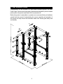
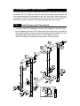
4. ASSEMBLE THE PRODUCT
Follow instructions below to assemble this product. Note that in this manual
the words “left” and “right” are used to refer to the product and its parts. As
such, these designations correspond to the “left” and “right” sides of a person
in position to exercise on this product. Also, for brevity, the word “screws” is
used where screws, washers, and other hardware may be involved.
STEP 1 Install Frames and Connectors
(a) First, remove nuts (31) and the curved connecting plates from the
connecter (A4) and U-shaped connecter (A2). Align the connecter (A4)
and U-shaped connecter (A2) to the holes in the right frame (A1) and left
frame (A3) and then loosely secure the assembly in place with the curved
connecting plates and nuts as shown. Do not tighten nuts yet.
(Note: For safety, two people are required for this procedure.)

8
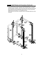
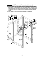
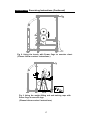
STEP 1 Install Frames and Connectors (Continued)
(b) First, remove nuts (31) and the curved connecting plates from the lower
connector (A15) and upper connecter (A12). Align the lower connector
(A15) and upper connecter (A12) to the holes in the front frame (A10) and
then loosely secure the assembly in place with the curved connecting
plates and nuts as shown. Do not tighten nuts yet.
(Note: Make sure the lower connector (A15) is assembled with the correct
direction.)

9
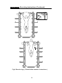
STEP 1 Install Frames and Connectors (Continued)
(c) Finally, remove nuts (32), screws (33) and U-shaped connecting plates
from the pull up bar connector (A11). Align the pull up bar connector (A11)
to the holes in the front frame (A10) and then loosely secure the assembly
in place with nuts (31), screws (33) and U-shaped connecting plates as
shown.
(d) Fully tighten all nuts once the whole assembly is completed.

10
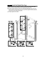
STEP 2 Install the Weight Plate Pegs
Follow instructions (a) through (c) below to install the weight plate pegs.
(a) First, remove screws (55) from the weight plate pegs (A7).
(b) Loosen screws (56) from the front of the right/left frame (A1) (A3) and
then install the weight plate pegs (A7) onto the right/left frame (A1) (A3)
and secure them with screws (55).
(c) Finally, tighten all screws.
(a) (b) (c)

11
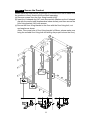
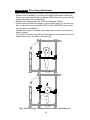
STEP 3 Secure the Product
Please follow the instructions (a) through (c) to secure the unit to make sure
the machine is firmly fixed to the floor when operating.
(a) Remove screws from the floor fixing bracket (A16).
(b) Insert the U-shaped clip (A17) onto the machine (Make sure the U-shaped
clip with the correct side downward as below shown), and then secure the
floor fixing bracket (A16) with screws.
(c) Secure the floor fixing bracket to the floor with the floor fixing bolt, nut
and washer as shown
(Note: The screw hole of floor fixing bracket is Ø9mm, please make sure
using the suitable floor fixing bolt and drilling the proper hole on the floor.)
(b)
(a)
(c)

12
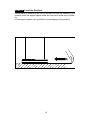
STEP 4 Level the Product
If the product is installed on an uneven surface to cause the instability of the
product, place the support spacer under the foot pad to make sure its stabil-
ity.
(A few support spacers are provided in the packaging of this product.)

13
STEP 5 Unit Inspection
After completing the assembly or regular maintenance, please follow instruc-
tions (a) through (c) below to inspect the unit. If the unit is disassembled or
has been damaged in any way, it might cause injuries or cause the unit to
fail.
(a) Make sure the unit is steady and on a level surface. If the unit is not
steady, make adjustments according to the instructions “Level the Unit”
of this manual.
(b) Make sure all parts are assembled and all fasteners are tightened.
(c) Please follow operating instructions to test operation and conrm that
the equipment is working properly. (Please refer to “Operate the Product”
of this manual.)

14
5. OPERATE THE PRODUCT
This section includes operational instructions.
OPERATION Operate the Product
Follow instructions (a) through (c) below to assembly and operate weight
lifting bar hook A/B (A5) (A6).
(a) Weight lifting bar hook A/B are designed to hang the weight lifting rod.
(b) Ensure the weight lifting bar A/B are installed at the same height.
Improper placement would not only damage the machine, but also may
present a danger to the exerciser.
(c) Align the axle of the weight lifting bar hook A/B to the holes in the right/
left frame and go through two holes of the tube and then turn the weight
lifting bar hook A/B to the proper direction as shown.
(Note: Make sure the weight lifting bar hook A/B are installed in the position
as shown. Improper placement may cause the product to fall.)
(Note: Make sure the weight lifting bar hook A/B (A5) (A6) are installed
higher than the safety catch bar A/B (A13) (A14).)
Follow instructions (a) through (c) below to assembly and operate safety
catch bar A/B (A13) (A14).
(a) Safety catch bar A/B are designed to hold the weight lifting rod when it
fall down unexpectedly during the operation.
(b) Ensure the proper workout position and placement of the safety catch bar
A/B prior to use.
(c) Ensure the safety catch bar A/B are installed at the same height.
Improper placement would not only damage the machine, but also may
present a danger to the exerciser.
(d) Insert the safety catch bar A/B (A13) (A14) to the right/left frame and go
through two holes of the tube and then turn the safety catch bar A/B
downward to insert the set pin to the frame and make the safety catch
bar A/B around the tube as shown. Follow the same procedure on both
sides.
(Note: Make sure both sides of safety catch bar A/B are inserted to the both
frames. If installed incorrectly, the safety catch bar A/B CAN NOT prevent
accidents by unexpected incidents.)

15
OPERATION Operate the Product (Continued)

16
OPERATION Exercising Instructions
* Note: While operating the machine, if the weight plate is moving around.
Please stop immediately, re-position the weight plate before continuing.
Secure the weight plates with set springs. Partial insertion may cause the
weight lifting bar to fall unexpectedly
* Weight limit: Weight plate limit of 250Kg (Unilateral 125Kg)
* Please exercise within the range of your skill and training. If you feel any
pain or any abnormal sensations, STOP YOUR WORKOUT and consult
your physician immediately
* Operate this machine must be supervised under coaches instructions in
order for safety.
* If you feel faint, pain or any abnormal sensations during exercise, put the
weight lifting rod on the safety catch bar A/B.
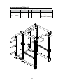
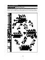
Fig 1. Exercise legs (*Please follow coaches’ instructions.)

17
OPERATION Exercising Instructions (Continued)
Fig 2. Using the bench with Power Cage to exercise chest.
(*Please follow coaches’ instructions.)
Fig 3. Using the weight lifting rod and training rope with
Power Cage to exercise legs.
(*Please follow coaches’ instructions.)

18
OPERATION Exercising Instructions (Continued)
Fig 4. Using the training rope with Power Cage to exercise arms.
(*Please follow coaches’ instructions.)
Fig 5. Using the training rope with Power Cage to exercise
chest and abdomen.
(*Please follow coaches’ instructions.)

19
OPERATION Exercising Instructions (Continued)
Fig 6. Exercise legs (*Please follow coaches’ instructions.)

20
6. MAINTENANCE
This section covers maintenance topics and includes a maintenance sched-
ule, task list, and log.
MAINTENANCE Safety Precautions
● Please follow standard safety precautions when servicing on this product.
● Do NOT use a damp towel to clean the product and do perform the fol-
lowing maintenances.
● Do NOT use cleaners with alcohol, ammonia, or other damaging chemi-
cals. The use of such chemicals can damage the product and void the war-
ranty. Never spray or pour any liquid directly onto the product. Doing so can
damage components and void the warranty.
● Use a clean, lint-free towel, dampened with a mixture of Simple Green®
all-purpose cleaner, to thoroughly clean the handlebar and the console.
● This product has moving parts that can be hazardous. Exercise caution
when maintaining, operating, or moving this product.
● Do not use accessories or parts that are not specically recommended
by the manufacturer (SportsArt) . Such parts might cause injuries or cause
the unit to fail and void the warranty. We will not be responsible for any
safety issue that arises due to the misuse of accessories or parts. At the
same time, we will terminate the warranty terms of this equipment.
● Maintenance and repair must be performed by trained service personnel
only. Improper maintenance would not only damage the machine, but also
may present a danger to the exerciser.
● Keep this product out of use until maintenance is completed.
La page est en cours de chargement...
La page est en cours de chargement...
La page est en cours de chargement...
La page est en cours de chargement...
La page est en cours de chargement...
La page est en cours de chargement...
La page est en cours de chargement...
-
 1
1
-
 2
2
-
 3
3
-
 4
4
-
 5
5
-
 6
6
-
 7
7
-
 8
8
-
 9
9
-
 10
10
-
 11
11
-
 12
12
-
 13
13
-
 14
14
-
 15
15
-
 16
16
-
 17
17
-
 18
18
-
 19
19
-
 20
20
-
 21
21
-
 22
22
-
 23
23
-
 24
24
-
 25
25
-
 26
26
-
 27
27


SportsArt A966 Le manuel du propriétaire
- Taper
- Le manuel du propriétaire
dans d''autres langues
- English: SportsArt A966 Owner's manual
Documents connexes
-
SportsArt A967 Le manuel du propriétaire
-
-
-
-
-
-
-
-
-