Camp Chef PG36CL Mode d'emploi
- Catégorie
- Barbecues
- Taper
- Mode d'emploi

www.CampChef.com | 1.800.650.2433 • Camp Chef is a registered trademark of Logan Outdoor Products
©2019 • Patent Pending • 3985 N 75 W, Hyde Park, UT 84318, USA • Made in China 0419_PG36CL_Booklet
PELLET GRILL AND SMOKER
WARNING & INSTRUCTION BOOKLET
MODEL NUMBER: PG36CL
2.4GHz

WARNING
FOR OUTDOOR USE ONLY
WARNING
If the information in this manual is not followed
exactly, a fire or explosion may result causing
property damage, personal injury or loss of life.
WARNING
• To installer or person assembling this appliance:
Leave this manual with this appliance for future
reference.
• To consumer: Keep this manual with this
appliance for future reference.
This instruction manual contains important
information necessary for the proper assembly
and safe use of this product. Read and follow
all warnings and instructions before assembling
and using this appliance. Do not discard this
instruction manual.
CAUTION
Use Only Wood Pellet Fuel Specified By The
Manufacturer. Do Not Use Pellet Fuel Labeled As
Having Additives. Only use Camp Chef Premium
Pellets with the following specifications. 8,000-
8,300 BTU/LB 0.75-0.85% Ash content
CAUTION
Contact local building or fire officials about
restrictions and installation inspection
requirements in your area.
A MAJOR CAUSE OF FIRES IS FAILURE TO
MAINTAIN REQUIRED CLEARANCES (AIR SPACES)
TO COMBUSTIBLE MATERIALS. IT IS OF UTMOST
IMPORTANCE THAT THIS PRODUCT BE INSTALLED
ONLY IN ACCORDANCE WITH THESE INSTRUCTIONS.
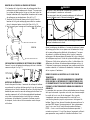
DANGER
1. Never operate this appliance unattended.
2. Never operate this appliance within 10 ft (3 m) of
a stored LP cylinder.
3. Never operate this appliance within 25 ft (7.5 m)
of any flammable liquid.
4. If a fire should occur, keep away from appliance
and immediately call your fire department. Do
not attempt to extinguish an oil or grease fire
with water.
Failure to follow these instructions could result
in fire, explosion or burn hazard, which could
cause property damage, personal injury or
death.
CAUTION
Always store wood pellets away from heat
producing appliances and other food containers.
Pellets should be stored in a dry environment.
WARNING
Normal use will create a buildup of ash, grease,
and creosote inside the grill. The grill must be
thoroughly cleaned after every 50 hours of use or
if a buildup of grease or creosote is noticed inside
the grill. Clean the grill by removing all internal
parts and thoroughly scrape away all grease and
creosote from all internal surfaces including the
grease drain and remove debris from the grill. The
drip tray must always be cleaned prior to turning
the grill to high or cooking in direct flame mode.
Excessive buildup of grease and creosote may
result in a grease fire. If a grease fire does occur,
turn off the grill using the main power switch and
close the lid. Leave the lid closed until the fire
extinguishes itself. If an uncontrolled fire does
occur, immediately call the local fire department.
Never put water on a grease fire.

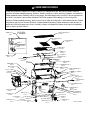
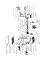
M8 LOCK WASHER (8)
PG36CL
0419 PG36CL PARTS
CHIMNEY CAP (1)
PG24-5
CHIMNEY (1)
PG24-6
UPPER COOKING RACK (2)
PG36SGX-7
LOWER GRATE (2)
PG24-70
PG36 LOWER GRATE (1)
PG36-21
M8 NUT (2)
HEAT DEFLECTOR (1)
PG24SG-2
HANDLE (1)
PG24-57
HANDLE BEZEL (2)
PG24-71
HANDLE DEFECTOR (1)
PG24-58
HANDLE SCREW (2)
PG24-59
SHELF (1)
PG36CL-1
M6 X 15 BOLT (5)
PULLOUT LOCK (1)
PG24-42
PULLOUT KNOB (2)
PG24-9
PG36 BURNER PULLOUT (1)
PG36-8
GREASE BUCKET (1)
PG24-11
M8 X 20 BOLT (8)
FRONT RIGHT LEG (1)
PG36-19
WHEEL (2)
PG24-16
WHEEL AXLE (2)
PG24-66
FRONT LEFT LEG (1)
PG36-17
ASH CUP (1)
PG24-17
PG36 SWIVEL CASTER (2)
PG36-7
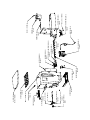
FEED GASKET (1)
PG24-34
PROBE COVER (1)
PG24-54
THERMOMETER (1)
PG24-44
PULL ROD (1)
PG24SG-3
M6 X 76 BOLT (1)
M6 NUT (2)
CHIMNEY GASKET (1)
PG24-7
M6 X 15 BOLT (2)
DRIP TRAY (1)
PG36SGX-1
SLIDE ROD (2)
PG36SGX-2
REAR LEFT LEG (1)
PG36-16
HOPPER ASM (1)
PG24CL-2
LID(1)
PG36SGX-8S
BOTTOM SHELF (1)
PG36-20
M10 ACORN NUT (2)
M10 FLAT WASHER (2)
REAR RIGHT LEG (1)
PG36-18
M8 FLANGE NUT (4)
M8 X 60 BOLT (4)
M6 X 15 SCREW (4)
UPPER GRATE BRACKET (2)
PG24SG-11
ST4.2 X 10 SCREW (6)
COVER PLATE (1)
PG36SGX0-1
CARBON MONOXIDE WARNING
Follow these guidelines to prevent this colorless, odorless gas from poisoning you, your family or others. Know the
symptoms of carbon monoxide poisoning: headache, dizziness, weakness, nausea, vomiting, sleepiness, and confusion.
Carbon monoxide reduces the blood’s ability to carry oxygen. Low blood oxygen levels can result in loss of consciousness
and death. See a doctor if you or others develop cold or flu-like symptoms while cooking or in the vicinity of this
appliance. Carbon monoxide poisoning, which can easily be mistaken for a cold or flu, is often detected too late. Alcohol
consumption and drug use increase the effects of carbon monoxide poisoning. Carbon monoxide is especially toxic to
mother and child during pregnancy, infants, the elderly, smokers and people with blood or circulatory system problems,
such as anemia, or heart disease.

LID MAGNET (1)
PGC24-18
POWER CORD (1)
PG24-48
HOPPER HANDLE (1)
PGC24-12
M6 X 15 BOLT (4)
M6 NUT (2)
PULLOUT KNOB (1)
PG24-9
PULLOUT LOCK (1)
PG24-42
BOTTLE OPENER (1)
BTOP-1
AUGER (1)
PGC24-8
AUGER PIN W/NUT (1)
PG24-25
AUGER BUSHING (1)
PG24-23
AUGER MOTOR WITH IMPELLER (1)
PG24-24
AUGER IMPELLER (1)
PG24-49
HEATING ROD (1)
PG24-21
BURNER (1)
PG24-78
M4.2 X 10 SCREW (4)
BLOWER IMPELLER (1)
PG24-27
M4.2 X 10 SCREW (4)
BLOWER MOTOR WITH IMPELLER (1)
PG24-26
MEAT PROBE (4)
PG24-28
M4 X 10 SCREW (2)
HOPPER LID (1)
PG24CL-3 (BLACK)
AUGER GUARD (1)
PG24CL-4
GUARD PLATE (1)
PG24CL-5
HOPPER WINDOW (1)
PG24CL-6
WIFI CONTROLER (1)
PG24CL-7
HOPPER CLEANOUT (1)
PG24CL-8

to cook with the lid closed.
18. Note that the cooking temperature displayed on the
digital readout is measured near the cooking surface on
the left side of the grill. The actual temperature inside
the cooking chamber will vary slightly throughout.
19. Do not use accessories not specified for use with
appliance.
20. Never use gasoline, gasoline-type lantern fuel,
kerosene, charcoal lighter fluid, or similar liquids to
start or freshen up a fire in this appliance. Keep all
such liquids well away from the appliance when in use.
21. Ashes should be placed in a metal container with a
tight fitting lid. The closed container of ashes should
be placed on a non combustible floor or on the ground,
well away from all combustible materials, pending final
disposal. When the ashes are disposed by burial in soil
or otherwise locally dispersed they should be retained
in the closed container until all cinders have thoroughly
cooled.
22. Creosote – Formation and need for removal. When wood
pellets are burned slowly, they produce tar and other
organic vapors that combine with expelled moisture
to form creosote. The creosote vapors condense in a
relatively cool oven flue and exhaust hood of a slow
burning fire. As a result, creosote residue accumulates
on the flue lining and exhaust hood. When ignited,
this creosote makes an extremely hot fire. The grease
duct should be inspected every 50 hours to determine
when grease and/or creosote build-up has occurred.
When grease or creosote has accumulated, it should be
removed to reduce risk of fire.
DANGER
Do not work on this grill if it is plugged in. Electric shock
may occur resulting in death or serious injury.
1. Do NOT leave this appliance unattended while in use.
The user must remain in the immediate area of the
product and have a clear view of the product at all times
during operation.
2. Keep children and pets away from grill at all times.
3. The use of alcohol, prescription or non-prescription drugs
may impair your ability to properly assemble or safely
operate this appliance.
4. For OUTDOOR use only. Do NOT use in a building,
garage or any other enclosed area. Do NOT use in or on
recreational vehicles or boats. NEVER use this appliance
as a heater.
5. Do not operate appliance under ANY overhead
construction. Keep a minimum clearance of 36 inches
(0.9 m) from the sides, front and back of appliance to
ANY construction. Keep the area clear of all combustible
material and flammable liquids, including wood, dry
plants and grass, brush, paper, and canvas.
6. This product is not intended for commercial use.
7. Always allow the appliance to cool before covering with
the patio cover.
8. Always cover the appliance, with patio cover (if
supplied), when not in use.
9. Always unplug grill before installing patio cover.
10. Use only on a level, stable non-combustible surface like
bricks, concrete or dirt. Do not use this appliance on
any surface that will burn or melt like wood, asphalt,
vinyl or plastic.
11. Make sure burner clean-out is closed before starting
the grill.
12. Make sure the grease bucket is in place before starting
the grill.
13. In the event of a fire unplug the grill from the power
supply, close the lid, and leave it closed until the fire
goes out. After allowing the grill to cool, follow the
cleaning instructions before the next use.
14. Use only food grade hardwood pellets manufactured for
use in pellet grills. Using softwood or heating pellets
will void your warranty.
15. Do not allow the hopper to run out of pellets. Pellets
can be added at any time. The hopper will hold
approximately 22 pounds of pellets. The pellet usage
will vary greatly depending on the ambient temperature
as well as cooking temperature.
16. It is recommended that you not store pellets in the
hopper for extended periods as they may absorb
moisture from the air and clog the auger.
17. Keep the lid closed during cooking. The grill is designed

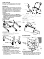
M8 X 60 BOLT
M8 FLANGE NUT
M6 X 15 SCREW
CHIMNEY GASKET
M6 NUT
M6 X 76 BOLT
FIG. 3
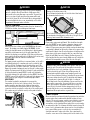
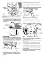
4. The height of the chimney cap can be adjusted for summer
and winter. In the summer the gap should be approximately
1-1/2”. In the winter the gap should be approximately ½”.
5. Tighten all hardware.
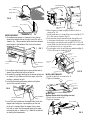
INSTALL HANDLE
1. Install the handle as shown in Fig 4.
2. Tighten all hardware.
PG24-57 (1)
HANDLE
PG24-59 (2)
M6 HANDLE SCREW
PG24-58 (1)
HANDLE DEFLECTOR
PG24-71 (2)
HANDLE BEZEL
FIG. 4
INSTALL HOPPER HANDLE
1. Install hopper handle as shown in Fig. 5.
FIG. 5
INSTALL HOPPER GUARD AND LID
1. Install guard and lid as shown in Fig. 6. The tab on the
hopper should be inserted into the slot on the guard. Use
screws to secure hopper guard and lid to the hopper.
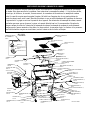
ASSEMBLY INSTRUCTIONS
Remove all loose parts from the inside of the grill and hopper.
Lay a blanket or piece of cardboard down to protect the grill.
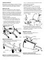
ATTACH THE LEGS
With the help of another person flip the grill upside down on the
blanket or cardboard. The grill lid and hopper lid will swing open
when doing this so be careful not to damage the lids. The grill
may also want to roll on its lid so one person should hold the
grill steady while the other person assembles the bottom legs
and wheels.
1. Lay the grill on its back.
2. Install each of the 4 legs as shown in Fig 1. Make sure the
legs with wheels are attached to the right side of the grill with
the wheels facing out. Note: Front legs are marked with an F
and back legs are marked with a B.
3. Stand the grill upright
4. Tighten all hardware.
M8 X 20 BOLT
M8 LOCK WASHER
FIG. 1
ATTACH BOTTOM SHELF
1. Install bottom shelf as shown in Fig. 2 by installing
hardware in each of the 4 corners.
2. Tighten hardware.
M8 X 60 BOLT
M8 FLANGE NUT
FIG. 2
ATTACH CHIMNEY AND CHIMNEY CAP
1. Install chimney to grill as shown in Fig 3. Make sure to
install the gasket between the grill and the chimney.
2. Tighten all hardware.
3. Install M6 x 76 Bolt through chimney cap and secure
using Qty (1) M6 nut. Thread second nut onto bolt leaving
approximately 1.5” to the top of the cap. Thread cap
assembly down into the chimney bracket until the lower nut
hits the bracket. See Fig 3.

M4 X 10 SCREW (2)
HOPPER LID (1)
HOPPER GUARD (1)
FIG. 6
HOPPER LID (1)
M4 X 10 SCREW (2)
HOPPER GUARD (1)
HOPPER ASSEMBLY
1. Assemble burner pullout as shown by sliding the rod
through the bottom hole on the right side of the grill as
shown in Fig. 7. Burner pullout plate should be centered
over the hole in the bottom of the stove and centered
between the guides.
PULLOUT KNOB (3)
PG24-9
PG36 BURNER PULLOUT (1)
PG36-8
HAIRPIN
STOP LOCK BUSHING (1)
PG24-76
FIG. 7
2. Assemble hairpin through hole in burner pullout rod to
prevent the pullout from pulling out too far.
3. Assemble the stop lock bushing on the burner pullout rod
as shown in Fig.8. Make sure that the larger side of the
bushing is towards the grill.
4. Install pullout knob onto burner pullout and tighten
against the stop lock bushing.
DETAIL A
PG36 BURNER PULLOUT (1)
PG36-8
HAIRPIN
SEE DETAIL A
PULLOUT KNOB (3)
PG24-9
STOP LOCK BUSHING (1)
PG24-76
FIG. 8
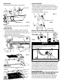
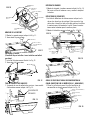
5. Install the feed gasket over the hopper tube. Install the
hopper tube through the square opening on the side
of the grill assembly. When the hopper tube is about
half way in, route the thermometer through the upper
rectangular hole as shown in Fig. 9. Note: Be careful not
to damage the thermometer.
FEED GASKET (1)
PG24-34
THERMOMETER (1)
PG24-44
HOPPER TUBE
ROUTE THERMOMETER
THROUGH THIS HOLE
FIG. 9
6. Attach hopper assembly using Qty (4) M6 x 15 bolts as
shown in Fig. 10.
7. Install thermometer as shown then secure using Qty (2) ST
4.2 x 10 screws as shown in Fig. 10
8. Push extra wire from thermometer back through the hole
to the hopper. Install probe cover to the wall where the
thermometer came thru the wall using QTY (2) ST 4.2 x 10
screws. Make sure that the notch in the cover is up and wire
goes through notch so it is not pinched.
9. Secure hopper end to the grill body assembly using Qty (2)
ST 4.2 x 10 screws as shown in Fig. 10
PG36 BURNER PULLOUT (1)
PG36-8
THERMOMETER (1)
PG24-44
HOPPER ASM (1)
PG24CL-2
COVER PLATE (1)
PG36SGX0-1
ST4.2 X 10 SCREW (6)
M6 X 15 BOLT (9)
HOPPER END
FIG. 10
INSTALL SHELF BRACKETS
1. Install the brackets as shown in Fig 11.
2. Tighten all hardware.
UPPER GRATE BRACKET (2)
PG24SG-11
M6 X 15 SCREW (4)
M6 FLANGE NUT (4)
FIG. 11
INSTALL SHELF
(Optional-Do not install if installing sear box)
1. Install shelf as shown in Fig 5.
2. Tighten all hardware
M6 HANDLE SCREW (2)
HANDLE DEFLECTOR
HANDLE
HANDLE BEZEL (2)
GREASE BUCKET
M6 X 15 SCREW
ASH CUP
FIG. 5

GREASE BUCKET
1. Hang grease bucket from tube as shown in Fig 13.
ASH CUP
GREASE BUCKET
ASH CUP
FIG. 13
ASH CUP
1. Install Ash Cup as shown in Fig 13. Never use grill without
Ash Cup in place.
INSTALL DRIP TRAY
1. Install heat deflector as shown on top of the two guide
rods. Route the pull rod through the hole on the left side
and install the jam nut and the grill knob. Tighten jam nut
against the knob to tighten in place.
2. Install the Drip Tray as shown in Fig 14 and Fig 15.
HEAT DEFLECTOR (1)
PG24SG-2
PULLOUT KNOB (3)
PG24-9
PULL ROD (1)
PG24SG-3
SLIDE ROD (2)
PG36SGX-2
M8 X 1 JAM NUT (1)
DRIP TRAY (1)
PG36SGX-1
FIG. 14
DRIP TRAY
FIG. 15
COOKING GRATES
1. Install the Cooking Grates as shown in Fig 16.
LOWER GRATE (2)
PG24-70
LOWER GRATE (1)
PG36-21
UPPER COOKING RACK (2)
PG36SGX-7
FIG. 16
CLEAN-OUT PORT KNOB
1. Clean-out Port knob must be pushed in when grill is on.
Make sure pullout lock is pushed down and locks the knob to
prevent inadvertent opening of the clean-out port. See Fig 17.
2. Lift pullout lock and pull clean-out port knob to empty ash
into ash cup. See Fig 18.
3. See instructions for burner clean-out.
CLEANOUT PORT CLOSED
CLEANOUT PORT OPEN
FIG. 17
CLEANOUT PORT CLOSED
CLEANOUT PORT OPEN
FIG. 18
HOPPER CLEAN-OUT KNOB ASSEMBLY INSTALLATION
Hand tighten the hopper clean-out knob as shown in Fig. 19.
PG24-9 (1)
PULLOUT KNOB
FIG. 19
DANGER
Never Operate the Pellet grill without the ash cup in place.
Make sure the burner clean-out port is closed and locked
before starting the grill.
WARMING RACK
COOKING GRATE
CLEANOUT PORT KNOB
CLEANOUT PORT KNOB
Never open the burner clean-out port when the grill is hot.
After cleaning out the burner make sure to close the burner
clean-out by pushing the clean-out port knob in on the right side
of the grill. Make sure to lift the pullout lock and push the clean-
out port knob all the way in and lock in place with the pullout
lock. Every 50 hours of use, remove the grill grates, grease tray,
and heat deflector and clean the inside of the grill. If you notice a
lot of ash blowing around in the grill it is time to vacuum it out.
FILLING THE AUGER TUBE
CAUTION: ONLY USE THE FEED SETTING WHEN HOPPER HAS RUN
OUT OF PELLETS. FEED SETTING IS NOT FOR NORMAL USE.
The first time you use your grill or any time the hopper has ran
out of pellets you will need to fill the auger tube. This simply
means you must fill the auger tube with pellets until pellets

reach the burner. This is done by selecting FEED from the main
menu. This will turn the auger on and the controller will display
“FEED”. The auger will remain on for no more than 7 minutes.
This is ample time for the pellets to reach the burner. It is easiest
to open the burner clean-out by pulling the knob on the right
side of the grill. Once you hear pellets dropping into the cup you
can close the clean-out port by pushing the knob on the right
side of the grill and then select your cooking temperature. (Never
operate grill without the ash cup in place). Always make sure
the burner clean-out port is closed by pushing in the knob on the
right side of the grill before selecting any of the cook settings.
Never open the burner clean-out port when the grill is hot.
APP QUICK START GUIDE
1. Download the Camp Chef APP from the Apple APP store or
Android Play Store.
2. Turn the Grill controller on using the main power switch.
3. Open the Camp Chef APP and follow the setup instructions for
connecting the grill to your home 2.4 GHz WiFi network.
Warning - Do NOT leave this appliance unattended while in use.
The user must remain in the immediate area of the product and
have a clear view of the product at all times during operation.
Note - Some functions are only available from the controller. If
attempting to start the grill from the APP it will prompt you to
confirm starting the grill from the controller. Temperature and
Smoke settings can be adjusted from the APP. Shutdown can
also be performed from the APP.
For more information visit https:/www.campchef.com/app
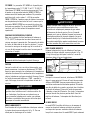
CONTROLLER EXPLANATION
POWER SWITCH
Used to turn the main power onto the pellet grill. “O” is Off. “-“
is On. See Fig. 20
Fig. 20
CONTROLLER FUNCTIONS
Rotate the dial to scroll through menus, adjust temperature, or
smoke settings. Press the dial to select.
SHUTDOWN
This setting must be used after each use. Select SHUTDOWN
from the main menu. The fan will remain on for up to 20
minutes. This setting will burn up any extra pellets in the burner
and cool down the grill. Do not turn the main power switch off
when the grill is hot.
FEED - Select FEED from the main menu. This setting is used to
feed pellets to the burner. It will be used the first time you use
the grill to fill the auger tube and any time you may inadvertently
run the hopper out of pellets. See instructions on filling the
auger tube.
SET TEMP LOW SMOKE - Select SET TEMP from the main menu.
Rotate dial to LOW SMOKE and press to confirm. This setting is
used for smoking foods at an average temperature of 160F. This
setting will produce large amounts of smoke.
SET TEMP HIGH SMOKE - - Select SET TEMP from the main
menu. Rotate dial to HIGH SMOKE and press to confirm. This
setting is used for smoking foods at an average temperature of
220F. This setting will produce large amounts of smoke.
SET TEMP 160F TO 450F - Select SET TEMP from the main menu.
Rotate dial to the desired temperature and press to confirm.
SET TEMP HIGH - Select SET TEMP from the main menu. Rotate
dial to HIGH and press to confirm. This setting can be used
to achieve temperatures up to 500F depending on ambient
temperatures.
SET SMOKE – The SET SMOKE setting is available for
temperatures from 160F – 350F. Select SET SMOKE from
the main menu. Rotate dial to the desired SMOKE SETTING
and press to confirm. The SMOKE SETTING can be adjusted
from 1-10. A smoke setting of 1 will produce less smoke and
maintain a more even temperature. As the smoke setting is
increased more smoke will be produced. Note that as the smoke
setting is increased temperature fluctuations will increase.
BREAKING IN THE GRILL
We suggest turning the grill to 350F for ½ hour before
cooking on the grill for the first time. This will burn off any
manufacturing oils and cure the paint. Make sure to follow the
instructions for filling the auger tube before breaking in the grill.
WARNING
Always start the grill with the lid open. The lid must be
closed after the start cycle.
COOKING
Once the auger tube has been properly filled you can begin
cooking by selecting SET TEMP from the main menu and
setting the desired temperature. Upon confirming the set
temperature the grill will go into the Startup mode. The control
will display START during the startup cycle. After 6 minutes the
control panel will change to the temperature display screen.
WARNING
Do not over-fire the grill by over feeding pellets into the burner
prior to startup. If flame is inadvertently extinguished never
restart the grill without first cleaning out the burner. Improper
use can cause an uncontrolled fire.
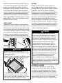
DIRECT FLAME MODE
Pull grill knob out all the way to allow direct heat as shown in
Fig 21. Best for burgers and steaks.
Fig. 21

WARNING
Always clean grease tray to remove excess grease drippings
prior to cooking in Direct Flame Mode. A dirty grease tray
may result in excessive flare ups or grease fire. If grease fire
does occur, turn off grill using the main power switch and
close the lid. Leave the lid closed until fire is extinguished. If
an uncontrollable fire does occur, immediately call local fire
department. Never put water on the fire.
INDIRECT FLAME MODE
Push grill knob in all the way for indirect heat as shown in Fig
22. Best for chicken, slow smoking and low temps.
Fig. 22
SHUTDOWN
When you are done cooking select SHUTDOWN from the main
menu. The display screen will display SHUTDOWN. In this
setting the fan will remain on for 20 minutes to finish burning
any pellets in the burner and cool the grill down. After 20
minutes the display screen will turn off. At this point the main
power switch should be switched to off. Before grill can be used,
the power switch must be turned off and back on.
BYPASS MODE
The bypass may be used if there is a power failure, or the grill is
accidentally turned off, or anytime you need to restart the grill
and it is still hot. The bypass mode should only be used if the
grill has been off less than 3-4 minutes. This method is used to
bypass the normal startup mode and get the grill cooking again
quickly. The burner must still be hot enough to ignite new pellets
or this method will not work. BYPASS can be selected during
the initial startup of the grill only by selecting BYPASS from the
STARTUP screen. If the grill fails to ignite using the bypass mode
then restart the grill using the normal startup procedures.
MEAT PROBES
This smoker has built in meat probes to measure the
temperature of the food as it is being cooked. To use these
probes insert the wire through the stainless flaps on the
side of the firebox. Insert the probes into the food. Plug the
connectors into the receptacles on the side of the control panel.
If the probes are not installed correctly or the probe is bad no
temperature will display.
PROBE
PROBE HOLE
CAUTION
Do not use meat probes when grill temperature exceeds 350˚F.
Damage to the probes may occur.
Do not allow meat probe wires to lie in the direct heat zones
(as shown by shaded areas).
Direct heat will damage the meat probe wires. Always route
the meat probes through ports on the side of the grill. Do not
submerge wire in water. Not dishwasher safe.
CLEANING
Clean grates using a wire grill brush. This should be done with
each use. DO NOT use oven cleaner or abrasive cleaners on the
painted grill surfaces. Use warm soapy water on all painted
surfaces. Clean grease pan, grease trough, and grease drain tube
occasionally. A spatula can be used to scrape excess grease and
a grill brush to brush clean. Do not allow grease to build up on the
grease tray or in the grease trough as this can cause flare-ups
inside the grill. Make sure not to obstruct the flow of grease off
of the tray and into the grease trough. Make sure not to block the
airflow to the temperature sensor on the left side of the grill.
WARNING
Normal use will create a buildup of ash, grease, and creosote
inside the grill. The grill must be thoroughly cleaned after
every 50 hours of use or if a buildup of grease or creosote
is noticed inside the grill. Clean the grill by removing all
internal parts and thoroughly scrape away all grease and
creosote from all internal surfaces including the grease drain
and remove debris from the grill. The drip tray must always
be cleaned prior to turning the grill to high or cooking in
direct flame mode. Excessive buildup of grease and creosote
may result in a grease fire. If a grease fire does occur, turn
off the grill using the main power switch and close the lid.
Leave the lid closed until the fire extinguishes itself. If an
uncontrolled fire does occur, immediately call the local fire
department. Never put water on a grease fire.
CHIMNEY CLEANING
When wood pellets are burned slowly, they produce tar and other
organic vapors that combine with expelled moisture to form
creosote. The creosote vapors condense in a relatively cook oven
chimney of a slow burning fire. As a result, creosote residue
accumulates on the chimney. When ignited, this creosote makes
an extremely hot fire. The chimney should be inspected every 50
hours of use to determine when grease and or creosote buildup
has occurred. When grease or creosote has accumulated, it
should be removed to reduce risk of fire. Use a wire brush to
clean the screen area of the chimney outlet on the inside of the

grill with every 50 hours of use. The chimney must be removed
and thoroughly cleaned to remove creosote and grease buildup
every 200 hours of use.
TROUBLESHOOTING
GRILL DOES NOT TURN ON.
Grill fails to turn on after switching the power button to the on
position.
1. Make sure the grill is plugged into a powered outlet. Check
the circuit breaker and/or GFCI switch. Test the outlet using
another appliance.
2. Unplug the grill and check the fuse located in the bottom of
the control panel. If the fuse is blown replace only with 4.0
Amp 125V 5x20mm Fast Blow Fuse. Typical fuse marking
will be 4A125V, F4A125V, 4A250V, or F4A250V. Make sure to
confirm they are a Fast Blow Fuse. Actual fuse dimensions are
5.2x20mm.
If problem cannot be resolved please call customer service.
GRILL DOES NOT HEAT UP OR CONTROLLER DISPLAYS FLAME
ERROR
1. Turn Power Off
2. Check hopper for pellets
3. Check firebox to see if there are pellets in the firebox. The
easiest way to do this is to pull the burner clean-out lever.
Then remove the cup from the bottom of the grill and check
for pellets. Use a vacuum to clean-out any pellets that may be
in the bottom of the grill.
A. If there are a lot of pellets in the cup. Reinstall the cup and
close the burner clean-out, remove the grill grates, grease
tray, and heat deflector and vacuum out any pellets in the
bottom of the grill. Try restarting the grill. If restarting the grill
does not work and pellets are getting to the burner cup the
heating rod may need to be replaced.
B. If there are few or no pellets in the cup then turn the dial
to the feed position and see if pellets fall out the bottom of
the burner. If there are no pellets check to see if the auger
is turning. If the auger motor is turning but the auger is not
there may be a sheared auger pin. You can determine if the
auger motor is turning by watching the small white fan at the
end of the auger motor under the hopper. If the white fan is
turning the auger motor is on. If the white fan is turning and
the auger is not you will need to replace the auger pin.
If problem cannot be resolved please call customer service.
CONTROLLER DISPLAYS SENSOR ERROR
1. Turn the power off and unplug the grill.
2. Check to make sure the sensor inside of the grill is
connected properly to the electronic board under the hopper.
3. Call customer service for a replacement sensor.
PROBE TEMPERATURES DO NOT DISPLAY
1. Make sure the meat thermometer is connected properly to
the controller.
2. Call customer service for a replacement meat thermometer.
CONTROLLER DISPLAYS OVER TEMP.
1. This happens if the internal temperature of the grill
exceeds a normal operating temperature. The grill must be
cleaned before attempting to start the grill.
LIMITED WARRANTY
Camp Chef No-Hassle Warranty
Here at Camp Chef we stand by our products and take pride in our
customer service. Because of this, your new Camp Chef product comes
with a No-Hassle Warranty. We warrant that our products will be free from
defects in all materials and workmanship (excluding paint and finish) for
the Warranty Coverage Period described below. This warranty is extended
only to the original consumer purchaser. During the Warranty Coverage
Period, we will (at our sole option) replace any defective part or product
covered by this warranty when provided with proof of purchase. The
replacement will be without charge.
Required Maintenance:
Clean your product after each use to maintain its finish and prolong its
lifespan. Wipe away all grease and ashes. Keep metal products free of
moisture, salts, acids and harsh fluctuations in temperature. Product
paint and other finishes are not covered by this warranty. The exterior
finish of the product will wear down over time.
Coverage Details:
Warranty does not cover normal wear of parts or damage caused by
misuse, abuse, overheating and alteration. No alterations are covered in
this warranty. Camp Chef is not responsible for any loss due to neglectful
operation. Furthermore, this warranty does not cover products damaged
or rendered defective due to accident, misuse, abuse, modification, water
damage, neglect, improper handling or storage, improper maintenance
or installation, incorporation of third party components or exposure to
weather, natural disasters such as earthquakes, hurricanes, tornadoes,
floods, lightning, fires, or failure to follow instructions for use.
ANY WARRANTIES IMPLIED BY LAW SHALL IN NO EVENT EXTEND BEYOND
DURATION OF THIS EXPRESS WARRANTY. Some States do not allow
limitations on how long an implied warranty lasts, so the above limitation
may not apply to you. REPAIR OR REPLACEMENT AS PROVIDED HEREIN IS
YOUR EXCLUSIVE REMEDY FOR ANY DEFECTIVE PRODUCT. IN NO EVENT
SHALL WE BE LIABLE FOR ANY SPECIAL, INCIDENTAL OR CONSEQUENTIAL
DAMAGES OF ANY KIND ARISING OUT OF THE PURCHASE OR USE OF
THIS PRODUCT, WHETHER BASED UPON CONTRACT, TORT, STATUTE OR
OTHERWISE. Some states do not allow the exclusion or limitation of
incidental or consequential damages, so the above limitation or exclusion
may not apply to you. This warranty gives you specific legal rights, and
you may also have other rights which vary from State to State.
Please keep all original sales receipts from the authorized dealer. Proof
of purchase is required to obtain warranty services. Any parts or products
returned without written authorization will be discarded without notice.
To obtain warranty services submit a warranty request at
www.campchef.com/warranty-information, email: [email protected]
or call (800) 650-2433. Our English speaking Product Specialists are happy
to help, Monday-Friday 7 AM – 5 PM MST.
Warranty applies to the United States and Canada.
WARRANTY COVERAGE PERIODS
Pellet Grills 3 years from purchase date
Stoves 1 year from purchase date
Fire Pits 1 year from purchase date
Water Heaters 1 year from purchase date
Movie Screens 1 year from purchase date
All other items & accessories 90 days from purchase date

CAUTION
This device complies with Part 15 of the FCC rules. Operation is subject to the following two conditions: 1 this device may not cause harmful interference,
and 2 this device must accept any interference received, including interference that may cause undesired operation.
Note: This equipment has been tested and found to comply with the limits for a Class B digital device, pursuant to part 15 of the FCC Rules. These limits
are designed to provide reasonable protection against harmful interference in a residential installation. This equipment generates, uses and can radiate
radio frequency energy and, if not installed and used in accordance with the instructions, may cause harmful interference to radio communications.
However, there is no guarantee that interference will not occur in a particular installation. If this equipment does cause harmful interference to radio or
television reception, which can be determined by turning the equipment off and on, the user is encouraged to try to correct the interference by one or more
of the following measures:
• Reorient or relocate the receiving antenna.
• Increase the separation between the equipment and receiver.
• Connect the equipment into an outlet on a circuit different from that to which the receiver is connected.
• Consult the dealer or an experienced radio/TV technician for help.
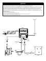
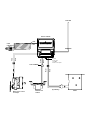
White
Black
4A 125V
4 amp 125V
5 x 20 MM
Fast Blow Fuse
Auger Motor
Blower Fan
Burner
Controller
RTD Sensor
Power Cord
White
Red
White
Orange
White
Purple
Hot Rod
MOLEX Connector

www.CampChef.com | 1.800.650.2433 • Camp Chef is a registered trademark of Logan Outdoor Products
©2019 • Brevet en attente • 3985 N 75 W, Hyde Park, UT 84318, USA • Fabriqué en Chine 0419_PG36CL_Booklet
BARBECUE À GRANULES ET FUMOIR
NOTICE D’UTILISATION ET AVERTISSEMENTS
NUMÉRO DE MODÈLE: PG36CL
2.4GHz

AVERTISSEMENT
DESTINÉ À UN USAGE EN PLEIN
AIR UNIQUEMENT
AVERTISSEMENT
Le non-respect à la lettre des renseignements
figurant dans la présente notice peut entraîner
un incendie ou une explosion qui pourrait
occasionner des dommages matériels, des
blessures corporelles ou la mort.
AVERTISSEMENT
• À l’attention de l’installateur ou de la personne
chargée d’assembler cet appareil : conserver
la présente notice d’utilisation avec l’appareil
pour un usage ultérieur.
• À l’attention du consommateur : conserver la
présente notice d’utilisation avec l’appareil
pour un usage ultérieur.
La présente notice d’utilisation contient des
informations importantes, nécessaires au
montage correct et à l’utilisation sécuritaire
de ce produit. Lire et respecter l’ensemble des
avertissements et consignes avant le montage
et l’utilisation de cet appareil. Ne pas jeter la
présente notice d’utilisation.
ATTENTION
Utiliser uniquement les granules de bois indiqués
par le fabricant. Ne pas utiliser de granules de
bois dont les spécifications indiquent la présence
d’additifs. Utiliser uniquement les granules
Camp Chef de première qualité répondant aux
spécifications suivantes. 8 000 à 8 300 BTU/LB.
Taux de cendres de 0,75 à 0,85 % (8,000-8,300
BTU/LB 0.75-0.85% ash content).
ATTENTION
Contacter les autorités locales du bâtiment ou de la
protection incendie pour connaître les restrictions et les
exigences d’inspection en vigueur dans votre région.
LE NON-RESPECT DES DÉGAGEMENTS OBLIGATOIRES
(ESPACES VIDES) PAR RAPPORT AUX MATÉRIAUX
COMBUSTIBLES EST UNE DES PRINCIPALES CAUSE
D’INCENDIE. IL EST EXTRÊMEMENT IMPORTANT
D’INSTALLER CE PRODUIT DANS LE STRICT RESPECT
DE CES CONSIGNES.
AVERTISSEMENT
1. Ne jamais faire fonctionner cet appareil sans
surveillance.
2. Ne jamais utiliser cet appareil à moins de 3 m
(10 pi) d’une bouteille de GPL entreposée.
3. Ne jamais utiliser le présent appareil à moins de
7,5 m (25 pi) de tout liquide inflammable.
4. En cas d’incendie, rester à bonne distance de
l’appareil et appeler immédiatement le service
des incendies. Ne pas essayer d’éteindre un feu
d’huile ou de graisse au moyen d’eau.
Le non-respect de ces consignes peut entraîner
des dommages matériels, des blessures corporelles
ou la mort pouvant résulter d’un incendie, d’une
explosion ou d’un danger de brûlure.
ATTENTION
Entreposer en permanence les granules de bois
à l’abri des appareils produisant de la chaleur
et d’autres récipients alimentaires. Les granules
doivent être entreposés dans un endroit sec.
AVERTISSEMENT
Une utilisation normale créera une accumulation
de cendres, de graisse et de créosote dans le
barbecue. Le barbecue doit être nettoyé à fond
toutes les 50 heures d’utilisation ou si une
accumulation de graisse ou de créosote est
observée à l’intérieur du barbecue. Nettoyer le
barbecue en enlevant toutes les pièces internes
et enlever soigneusement toutes les graisses
et la créosote de toutes les surfaces internes, y
compris le tuyau d’évacuation des graisses et
enlever les débris du barbecue. La lèchefrite doit
toujours être nettoyée avant de mettre le barbecue
en position haute ou de cuire en mode flamme
directe. Une accumulation excessive de graisse et
de créosote peut provoquer un feu de graisse. En
cas d’incendie provoqué par la graisse, éteindre
l’appareil au niveau de l’interrupteur principal
et fermer le couvercle. Laisser le couvercle fermé
jusqu’à l’extinction totale du feu. En cas d’incendie
incontrôlable, appeler immédiatement le service
local des incendies. Ne jamais verser de l’eau sur
un feu de graisse.

RONDELLE FREIN M8 (8)
PG36CL
0419 PG36CL PARTS
ENSEMBLE DU CHAPEAU
DE LA CHEMINÉE (1)
PG24-5
CHEMINÉE (1)
PG24-6
GRILLE SUPÉRIEURE (2)
PG36SGX-7
GRILLE DE CUISSON (2)
PG24-70
PG36 GRILLE DE CUISSON (1)
PG36-21
ÉCROU M8 (2)
DÉFLECTEUR DE CHALEUR (1)
PG24SG-2
POIGNÉE (1)
PG24-57
COLLERETTE D’ENCASTREMENT
DE LA POIGNÉE (2)
PG24-71
DÉFLECTEUR DE LA POIGNÉE (1)
PG24-58
VIS DE LA POIGNÉE M6 (2)
PG24-59
ÉTAGÈRE LATÉRALE (1)
PG36CL-1
BOULON M6 X 15 (4)
SYSTÈME DE BLOCAGE DE
LA TRAPPE DU BRÛLEUR (1)
PG24-42
BOUTON DE TRAPPE (2)
PG24-9
TRAPPE DU BRÛLEUR (1)
PG36-8
SEAU DE COLLECTE DES GRAISSES (1)
PG24-11
BOULON M8 X 20 (8)
PIED AVANT DROIT (1)
PG36-19
ROULETTE (2)
PG24-16
AXE DE ROULETTE (2)
PG24-66
PIED AVANT GAUCHE (1)
PG36-17
RÉCIPIENT À CENDRES (1)
PG24-17
PG36 SWIVEL CASTER (2)
PG36-7
JOINT DU SYSTÈME (1)
PG24-34
COUVERCLE DE SONDE (1)
PG24-54
THERMOMÈTRE (1)
PG24-44
TIGE DU DÉFLECTEUR (1)
PG24SG-3
M6 X 76 BOLT (1)
M6 NUT (2)
BOULON 1/4-20 X 3 (1)
PG24-7
ÉCROU 1/4-20 (2)
LÈCHEFRITE (1)
PG36SGX-1
SLIDE ROD (2)
PG36SGX-2
PIED ARRIÈRE GAUCHE (1)
PG36-16
HOPPER ASM (1)
PG24CL-2
COUVERCLE (1)
PG36SGX-8S
PLATEAU DU BAS (1)
PG36-20
ÉCROU BORGNE M10 (2)
RONDELLE PLATE M10 (2)
PIED ARRIÈRE DROIT (1)
PG36-18
ÉCROU À EMBASE M8 (4)
M8 X 60 BOLT (4)
VIS M6 X 15 (4)
SUPPORT DE GRILLE SUPÉRIEURE (2)
PG24SG-11
ST4.2 X 10 SCREW (6)
COVER PLATE (1)
PG36SGX0-1
AVERTISSEMENT CONCERNANT LE MONOXYDE DE CARBONE
Respecter les présentes directives pour éviter de vous faire intoxiquer et d’intoxiquer vos proches par ce gaz incolore
et inodore. Vous devez connaître les symptômes d’une intoxication au monoxyde de carbone : il s’agit de maux de tête,
de vertiges, de faiblesses, de nausées, de vomissements, de somnolence et de confusion. Le monoxyde de carbone
réduit la capacité sanguine pour transporter l’oxygène. Un faible taux d’oxygène dans le sang peut entraîner des
pertes de connaissance, voire la mort. Consulter un médecin si vous ou autrui développez des symptômes du rhume ou
s’apparentant à la grippe en cuisinant à proximité de cet appareil. Une intoxication au monoxyde de carbone, souvent
confondue par erreur avec un rhume ou la grippe, est souvent détectée trop tard. La consommation d’alcool ou de
drogues renforce les effets de l’intoxication au monoxyde de carbone. Le monoxyde de carbone est particulièrement
toxique pour les femmes enceintes et leur fœtus, les jeunes enfants, les personnes âgées, les fumeurs et les personnes
souffrant de troubles sanguins ou circulatoires, comme l’anémie ou des maladies cardiaques.

AIMANT DE COUVERCLE (1)
PGC24-18
CORDON D'ALIMENTATION (1)
PG24-48
POIGNÉE DU RÉSER
VOIR (1)
PGC24-12
BOULON M6 X 15 (4)
ÉCROU M6 (2)
BOUTON DE TRAPPE (1)
PG24-9
SYSTÈME DE BLOCAGE DE LA TIGE DE
NETTOYAGE DU RÉSERVOIR (1)
PG24-42
DÉCAPSULEUR (1)
BTOP-1
VIS SANS FIN DE TRANSPORT (1)
PGC24-8
AXE DE LA VIS SANS FIN AVEC ÉCROU (1)
PG24-25
DOUILLE DE LA VIS SANS
FIN DE TRANSPORT (1)
PG24-23
MOTEUR DE LA VIS SANS FIN
DE TRANSPORT AVEC ROUE (1)
PG24-24
ROUE DE LA VIS SANS FIN DE TRANSPORT (1)
PG24-49
BOUGIE D'ALLUMAGE (1)
PG24-21
BRÛLEUR (1)
PG24-78
VIS M4.2 X 10 (4)
ROUE DE LA SOUFFLERIE (1)
PG24-27
VIS M4.2 X 10 (4)
MOTEUR DE LA SOUFFLERIE A
VEC ROUE (1)
PG24-26
SONDE À VIANDE (4)
PG24-28
VIS M4 X 10 (2)
COUVERCLE DU RÉSERVOIR (1)
PG24CL-3 (NOIR)
GRILLE DE PROTECTION DE
LA VIS SANS FIN DE TRANSPORT (1)
PG24CL-4
PLAQUE DE PROTECTION (1)
PG24CL-5
FENÊTRE DU RÉSERVOIR (1)
PG24CL-6
UNITÉ DE COMMANDE WI-FI (1)
PG24CL-7
TIGE DE NETTOYAGE
DU RÉSERVOIR (1)
PG24CL-8

16. Il vous est recommandé de ne pas entreposer de
granules dans le réservoir pour des périodes prolongées
; ils peuvent en effet absorber l’humidité de l’air et
obstruer la vis sans fin de transport.
17. Garder le couvercle fermé pendant le fonctionnement
du barbecue. Le barbecue est conçu pour une cuisson à
couvercle fermé.
18. Il convient de noter que la température de cuisson
affichée sur l’écran de l’unité de commande est mesurée
près de la surface de cuisson sur le côté gauche du
barbecue. La véritable température à l’intérieur de la
chambre de cuisson variera légèrement tout au long de
la cuisson.
19. Ne pas utiliser d’accessoires dont l’utilisation n’est pas
indiquée avec cet appareil.
20. Ne jamais employer d’essence, de carburant de lanterne
de type essence, de kérosène, de produit d’allumage
pour charbon ou de liquides semblables pour démarrer
ou raviver un feu dans cet appareil. Garder tous ces
liquides à bonne distance de l’appareil pendant qu’il est
en service.
21. Les cendres doivent être déposées dans un conteneur
métallique possédant un couvercle hermétique. Le
conteneur fermé qui contient les cendres doit être placé
sur une surface non combustible ou sur le sol, très loin
de tous les matériaux combustibles jusqu’à l’élimination
définitive des cendres. Les cendres qui sont destinées à
être enterrées dans le sol ou dispersées autrement sur
place doivent être conservées dans le conteneur jusqu’à
ce qu’elles soient complètement refroidies.
22. La créosote – Formation et nécessité de la retirer.
Lors de leur lente combustion, les granules de bois
produisent du goudron et d’autres vapeurs organiques
qui, combinés à l’humidité rejetée, forment la créosote.
Les vapeurs de créosote se condensent dans les
tuyaux d’évacuation d’un four relativement froid et
dans la hotte de ventilation d’un foyer à combustion
lente. Il en résulte une accumulation de résidus de
créosote dans les tuyaux d’évacuation et la hotte de
ventilation. Une fois mise à feu, cette créosote produit
un feu extrêmement chaud. Le tuyau d’évacuation
des graisses doit être inspecté au moins toutes les 50
heures pour déterminer si une accumulation de graisse
et/ou de créosote s’est produite. Si tel est le cas, cette
accumulation doit être enlevée pour réduire le risque
d’incendie.
DANGER
Ne pas effectuer de travaux sur le barbecue lorsque
celui-ci est branché. L’électrocution qui risquerait de se
produire peut entraîner le décès ou des blessures graves.
1. NE PAS laisser l’appareil sans surveillance lorsqu’il
fonctionne. L’utilisateur est tenu de rester à proximité du
produit et de garder celui-ci dans son champ de vision
direct pendant toute la durée de son fonctionnement.
2. Tenir les enfants et animaux domestiques à l’écart du
brûleur en permanence.
3. La consommation d’alcool ou de médicaments obtenus
ou non sur ordonnance risque de diminuer votre faculté
de monter correctement l’appareil ou de l’utiliser en toute
sécurité.
4. Destiné à un usage EN PLEIN AIR uniquement. NE PAS
utiliser à l’intérieur d’un immeuble, d’un garage ou de
tout autre endroit renfermé. NE PAS utiliser dans un
véhicule récréatif ou sur un bateau. NE JAMAIS utiliser cet
appareil comme système de chauffage.
5. Ne faire fonctionner cet appareil sous AUCUNE surface
surplombante. Conserver une distance minimale de 0,9 m
(36 pouces) entre les quatre côtés de l’appareil et TOUTE
construction. N’entreposer aucun matériau combustible
et aucun liquide inflammable, y compris du bois, des
plantes et herbes sèches, des buissons, du papier et des
toiles à proximité de l’appareil.
6. Ce produit n’est pas destiné à un usage commercial.
7. Toujours laisser refroidir l’appareil avant de le recouvrir
de sa housse d’extérieur.
8. Toujours recouvrir l’appareil de sa housse d’extérieur
(lorsqu’elle est fournie) lorsqu’il ne sert pas.
9. Toujours débrancher le barbecue avant de le recouvrir de
la housse d’extérieur.
10. Utiliser uniquement sur une surface stable et non
combustible comme les briques, le béton ou une surface
en terre. Ne pas utiliser cet appareil sur une surface qui
peut brûler ou fondre comme du bois, de l’asphalte, du
vinyle ou du plastique.
11. S’assurer que la zone de nettoyage du brûleur est
fermée avant d’allumer le barbecue.
12. S’assurer que le seau de collecte des graisses est monté
avant d’allumer le barbecue.
13. En cas d’incendie, débrancher le barbecue, fermer le
couvercle et le laisser fermé jusqu’à extinction du feu.
Lorsque le barbecue aura refroidi, suivre les consignes
de nettoyage avant la prochaine utilisation.
14. Utiliser uniquement des granules de feuillu à usage
alimentaire qui sont fabriqués pour être utilisés dans
des barbecues à granules. L’utilisation de granules
de conifères ou de bois de chauffage annulera votre
garantie.
15. Ne pas laisser le réservoir à granules se vider
complètement. Les granules peuvent être ajoutés à
tout moment. Le réservoir peut contenir environ 10 kg
de granules. La consommation de granules variera
considérablement en fonction de la température
ambiante ainsi que de la température de cuisson.

CONSIGNES DE MONTAGE
Retirer toutes les pièces détachées se trouvant à l’intérieur
du barbecue et du réservoir. Déposer une couverture ou un
morceau de carton par terre pour protéger le barbecue.
MONTAGE DES PIEDS
Avec l’aide d’une autre personne, mettre le barbecue à
l’envers sur la couverture ou le carton. Les couvercles du
barbecue et du réservoir s’ouvriront lors de cette opération.
Veiller à ne pas les abîmer. Le barbecue risque également
de rouler sur son couvercle. Une personne devrait donc le
maintenir en place pendant que l’autre personne monte les
pieds fixes et les roues.
1. Coucher le barbecue sur le côté arrière.
2. Monter chacun des 4 pieds comme indiqué à la Fig.
1. S’assurer que les pieds équipés de roulettes sont
attachés du côté droit du barbecue, les roulettes se
trouvant vers l’extérieur. Remarque : les pieds avant
portent la lettre F et les pieds arrière, la lettre B.
3. Remettre le barbecue à l’endroit.
4. Serrer toute la quincaillerie.
BOULON M8 X 20
ÉCROU À BRIDE M8
FIG. 1
MONTAGE DU PLATEAU DU BAS
1. Monter le plateau du bas, comme indiqué à la Fig. 2 en
attachant la quincaillerie aux quatre coins.
2. Serrer la quincaillerie.
M8 X 60 BOLT
M8 FLANGE NUT
FIG. 2
MONTAGE DE LA CHEMINÉE ET DE SON CHAPEAU
1. Monter la cheminée sur le barbecue comme indiqué à
la Fig. 3. S’assurer que le joint de la cheminée est placé
entre le barbecue et la cheminée.
2. Serrer toute la quincaillerie.
3. Placer le boulon M6 x 76 à travers le chapeau de la
cheminée et l’attacher au moyen d’un (1) écrou M6.
Visser le second écrou sur le boulon en laissant environ
3,8 cm à partir de l’extrémité supérieure du chapeau.
Visser l’ensemble du chapeau vers le bas dans le support
de la cheminée jusqu’à ce que l’écrou du bas touche le
support. Voir la Fig. 3.
BOULON M6 X 76
ECROU M6
VIS M6 X 15
CHEMINEE JOINT
RONDELLE PLATE M6
RO
NDELLE FREIN M
6
ECROU M6
FIG. 3
4. Il est possible d’ajuster la hauteur du chapeau de la
cheminée en fonction de l’été et de l’hiver. L’écart doit
être d’environ 3,8 cm en été, et d’environ 1,3 cm en hiver.
5. Serrer toute la quincaillerie.
MONTAGE DE LA POIGNÉE
1. Monter la poignée comme indiqué à la Fig. 4.
2. Serrer toute la quincaillerie.
PG24-57 (1)
POIGNÉE
PG24-59 (2)
VIS DE LA POIGNÉE M6
PG24-58 (1)
DÉFLECTEUR DE LA POIGNÉE
PG24-71 (2)
COLLERETTE D’ENCASTREMENT
DE LA POIGNÉE
FIG. 4
MONTAGE DE LA POIGNÉE DU RÉSERVOIR
1. Monter la poignée du réservoir comme indiqué à la Fig. 5.

FIG. 5
MONTAGE DE LA GRILLE DE SÉCURITÉ ET DU COUVERCLE
DU RÉSERVOIR
1. Monter la grille et le couvercle comme indiqué à la Fig. 6.
La languette du réservoir doit être insérée dans la fente
de la grille. Attacher la grille et le couvercle au réservoir
avec des vis.
VIS M4 X 10 (2)
COUVERCLE DE TRÉMIE (1)
GARDE DE TRÉMIE (1)
FIG. 6
COUVERCLE DE TRÉMIE (1)
VIS M4 X 10 (2)
GARDE DE TRÉMIE (1)
INSTALLER LA TRÉMIE
1. Assemblez le retrait du brûleur tel qu’illustré en faisant
glisser la tige à travers le trou du bas sur le côté droit de
la grille comme indiqué sur la Fig. 7. La plaque de retrait
du brûleur doit être centrée sur le trou dans le bas du
poêle et centrée entre les guides.
BOUTON DE TRAPPE (3)
PG24-9
PG36 BURNER PULLOUT (1)
PG36-8
ÉPINGLE À CHEVEUX
STOP LOCK BUSHING (1)
PG24-76
FIG. 7
2. Assemblez l’épingle à travers le trou dans la tige de
retrait du brûleur pour empêcher l’arrachement de tirer
trop loin.
3. Assembler la bague de blocage d’arrêt sur la tige de
retrait du brûleur, comme indiqué sur la Fig.8. Assurez-
vous que le plus grand côté de la bague est orienté vers
le gril.
4. Installez le bouton d’extraction sur l’extracteur du brûleur
et serrez contre la douille de verrouillage d’arrêt.
DETAIL A
PG36 BURNER PULLOUT (1)
PG36-8
HAIRPIN
SEE DETAIL A
BOUTON DE TRAPPE (3)
PG24-9
STOP LOCK BUSHING (1)
PG24-76
FIG. 8
5. Monter le joint du système d’alimentation sur le
réservoir. Installer le réservoir par l’ouverture carré
sur le côté latéral du corps du fumoir. Lorsqu’il est
inséré à mi-course, faites passer le thermomètre par le
trou rectangulaire du haut comme indiqué à la Fig. 9.
Remarque : attention de ne pas abîmer le thermomètre.
JOINT D'ALIMENTATION (1)
PG24-34
THERMOMÈTRE(1)
PG24-44
TUBE DE TRÉMIE
THERMOMÈTRE DE ROUTE
À TRAVERS CE TROU
FIG. 9
6. Monter l’ensemble du réservoir avec quatre boulons M6 x
15 comme illustré à la Fig. 10.
7. Monter le thermomètre comme illustré, puis attacher avec
2 vis ST 4.2 x 10.
8. Pousser le fil restant du thermomètre dans le trou vers
le réservoir. Monter le cache de la sonde sur la paroi à
travers laquelle le thermomètre est passé en utilisant
deux vis ST 4.2 x 10. Vérifier que l’encoche du cache est
vers le haut et que le fil passe à travers l’encoche pour
éviter d’être pincé.
9. Attacher l’extrémité du réservoir à l’ensemble du fumoir
avec deux vis ST 4.2 x 10. à la Fig. 10

PG36 BURNER PULLOUT (1)
PG36-8
THERMOMETER (1)
PG24-44
HOPPER ASM (1)
PG24CL-2
COVER PLATE (1)
PG36SGX0-1
ST4.2 X 10 SCREW (6)
M6 X 15 BOLT (9)
HOPPER END
FIG. 10
MONTAGE DE LA SUPPORT
1. Monter la support comme indiqué à la Fig. 11.
2. Serrer toute la quincaillerie.
UPPER GRATE BRACKET (2)
PG24SG-11
M6 X 15 SCREW (4)
M6 FLANGE NUT (4)
FIG. 11
INSTALLER L’ÉTAGÈRE
(Facultatif-Ne pas installer si vous installez une boîte à
garniture)
1. Installer l’étagère comme illustré à la Fig 12.
2. Serrez tous les accessoires
M6 HANDLE SCREW (2)
HANDLE DEFLECTOR
HANDLE
HANDLE BEZEL (2)
GREASE BUCKET
M6 X 15 VIS
ASH CUP
FIG. 12
SEAU DE COLLECTE DES GRAISSES
1. Suspendre le seau de collecte des graisses à son conduit
d’évacuation comme indiqué à la Fig. 13.
RÉCIPIENT
À CENDRES
SEAU DE COLLECTE
DES GRAISSES
FIG. 13
ASH CUP
RÉCIPIENT À CENDRES
1. Monter le récipient à cendres comme indiqué à la Fig. 13.
Ne jamais utiliser le barbecue sans y monter le récipient
à cendres.
DÉFLECTEUR DE LÈCHEFRITE
1. Installez le déflecteur de chaleur comme indiqué sur le
dessus des deux tiges de guidage. Faites passer la tige
de traction à travers le trou sur le côté gauche et installez
le contre-écrou et le bouton de la grille. Serrez le contre-
écrou contre le bouton pour le serrer en place.
2. Monter la lèchefrite comme indiqué aux Fig. 14 et 15.
DEFLECTEUR DE CHALEUR (1)
PG24SG-2
BOUTON DE SORTIE (3)
PG24-9
PULL ROD (1)
PG24SG-3
CANNE COULISSANTE (2)
PG36SGX-2
M8 X 1 JAM NUT (1)
LÈCHEFRITE (1)
PG36SGX-1
FIG. 14
LÈCHEFRITE
FIG. 15
GRILLE DE CUISSON ET GRILLE DE CONSERVATION AU
CHAUD (EN OPTION SUR LE MODÈLE PG24-1, NON INCLUS)
1. Placer la grille de cuisson et la grille facultative de
conservation au chaud comme indiqué à la Fig. 16.
GRILLE DE CUISSON (2)
PG24-70
GRILLE DE CUISSON (1)
PG36-21
GRILLE DE CUISSON SUPÉRIEURE (2)
PG36SGX-7
FIG. 16
La page est en cours de chargement...
La page est en cours de chargement...
La page est en cours de chargement...
La page est en cours de chargement...
La page est en cours de chargement...
La page est en cours de chargement...
La page est en cours de chargement...
La page est en cours de chargement...
-
 1
1
-
 2
2
-
 3
3
-
 4
4
-
 5
5
-
 6
6
-
 7
7
-
 8
8
-
 9
9
-
 10
10
-
 11
11
-
 12
12
-
 13
13
-
 14
14
-
 15
15
-
 16
16
-
 17
17
-
 18
18
-
 19
19
-
 20
20
-
 21
21
-
 22
22
-
 23
23
-
 24
24
-
 25
25
-
 26
26
-
 27
27
-
 28
28


Camp Chef PG36CL Mode d'emploi
- Catégorie
- Barbecues
- Taper
- Mode d'emploi
dans d''autres langues
Documents connexes
-
Camp Chef PG36SGXCB Mode d'emploi
-
Camp Chef Woodwind Mode d'emploi
-
-
-
-
-
-
-
-