NOMA Cassian Outdoor Le manuel du propriétaire
- Catégorie
- Ventilateurs ménagers
- Taper
- Le manuel du propriétaire

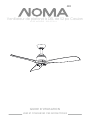
CASSIAN 52” LED CEILING FAN
PRODUCT NO. 052-9722-4
USER MANUAL
READ AND SAVE THESE INSTRUCTIONS

TABLE OF CONTENTS

3
01. SAFETY/CAUTIONS1
02. TOOLS REQUIRED
03. EXPLODED VIEW
04. ELECTRICAL SAFETY
05. ASSEMBLY
06. OPERATION
07. TROUBLESHOOTING
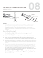
08. DYNAMIC BLADE BALANCING KIT
09. MAINTENANCE
10. WARRANTY & DISPOSAL
4
6
7
11
13
19
21
23
25
26
11. IC STATEMENT 27

4
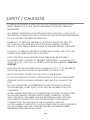
SAFETY / CAUTIONS
•
•
•
•
•
•
•
•
•
•
TO REDUCE THE RISK OF ELECTRIC SHOCK, ENSURE ELECTRICITY HAS
BEEN TURNED OFF AT THE CIRCUIT BREAKER OR FUSE BOX BEFORE
BEGINNING.
ALL WIRING MUST BE IN ACCORDANCE WITH NATIONAL AND LOCAL
ELECTRICAL CODES. ELECTRICAL INSTALLATION SHOULD BE PERFORMED
BY A QUALIFIED LICENSED ELECTRICIAN.
WARNING: TO REDUCE THE RISK OF ELECTRIC SHOCK OR FIRE, DO
NOT USE THIS FAN WITH ANY SOLID-STATE FAN-SPEED CONTROL
DEVICE. IT WILL PERMANENTLY DAMAGE THE ELECTRONIC CIRCUITRY.
CAUTION: TO REDUCE THE RISK OF PERSONAL INJURY, USE ONLY THE
SCREWS PROVIDED WITH THE OUTLET BOX.
THE OUTLET BOX AND SUPPORT STRUCTURE MUST BE SECURELY
MOUNTED AND CAPABLE OF RELIABLY SUPPORTING A MINIMUM OF
SUPPORT.”
AVOID PLACING OBJECTS IN THE PATH OF THE BLADES.
TO AVOID PERSONAL INJURY OR DAMAGE TO THE FAN AND OTHER
ITEMS BE CAUTIOUS WHEN WORKING AROUND OR CLEANING THE
FAN.
DO NOT USE WATER OR DETERGENTS WHEN CLEANING THE FAN
OR FAN BLADES. A DRY DUST CLOTH WILL BE SUITABLE FOR MOST
CLEANING.
AFTER MAKING ELECTRICAL CONNECTIONS, SPLICED CONDUCTORS
SHOULD BE TURNED UPWARD AND PUSHED CAREFULLY UP INTO
THE OUTLET BOX. THE WIRES SHOULD BE SPREAD APART WITH THE
GROUNDED CONDUCTOR AND THE EQUIPMENT-GROUNDING
CONDUCTOR ON ONE SIDE OF THE OUTLET BOX AND THE
UNGROUNDED CONDUCTOR ON THE OTHER SIDE OF THE OUTLET BOX.
ALL SET SCREWS MUST BE CHECKED AND RE-TIGHTENED WHERE
NECESSARY BEFORE INSTALLATION.
FROM THE TRAILING EDGE OF THE BLADES TO THE FLOOR.
35 LB (15.9 KG). USE ONLY UL-LISTED OUTLET BOXES MARKED “FOR FAN
THE FAN MUST BE MOUNTED WITH A MINIMUM OF 6’11’’(2.1M) FROM

5
01
•
•
•
WARNING: TO REDUCE THE RISK OF FIRE, ELECTRIC SHOCK
AND PERSONAL INJURY, MOUNT FAN TO OUTLET BOX MARKED
“ACCEPTABLE FOR FAN SUPPORT” WITH THE SCREWS PROVIDED WITH
THE OUTLET BOX.
WARNING: TO AVOID RISK OF PERSONAL INJURY, DO NOT BEND THE
BLADE ARMS (ALSO REFERRED TO AS FLANGES) OR THE BRACKETS
WHILE BALANCING THE BLADES OR CLEANING THE FAN. DO NOT
INSERT FOREIGN OBJECTS BETWEEN ROTATING FAN BLADES.
WARNING: TO REDUCE THE RISK OF FIRE, ELECTRIC SHOCK
AND PERSONAL INJURY, MOUNT FAN TO OUTLET BOX MARKED
“ACCEPTABLE FOR FAN SUPPORT” OF 35 LB (15.9 KG) OR LESS”
AND USE MOUNTING SCREWS PROVIDED WITH THE OUTLET BOX.
MOST OUTLET BOXES COMMONLY USED FOR THE SUPPORT OF
LIGHT FIXTURES ARE NOT ACCEPTABLE FOR FAN SUPPORT AND MAY
NEED TO BE REPLACED. DUE TO THE COMPLEXITY OF THIS FAN, A
QUALIFIED LICENSED ELECTRICIAN IS STRONGLY RECOMMENDED FOR
INSTALLATION.

6
01 02
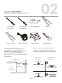
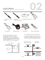
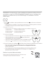
TOOLS REQUIRED
INSTALLATION PREPARATION
Flat-head
screwdriver
Cross-head
screwdriver
Safety glasses Pliers
Wire cutters Electrical tape Stepladder Wire strippers
6' 11"
(2.1 m)
30”
(76 cm )
To prevent personal injury and
damage, ensure that the hanging
location allows the blades a
clearance of 6' 11" (2.1 m) from the
floor and 30" (76 cm) from any wall or
obstruction.
This fan can be mounted with a
downrod on a regular (no-slope) or
vaulted ceiling, such as flush mount.
Flush Mount
Installation
Downrod
Installation
Vaulted
ceiling angle
is not to
exceed 18°
Blade Edge

7
03
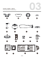
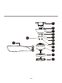
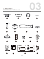
EXPLODED VIEW
PACKAGE CONTENTS
07
10 11 12 13
15 16 17
03
09
14
05 06 08
Installation
Instruction
X 3
X 2
X 3
X 3
X 2
X 1 X 3
X 3

8
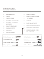
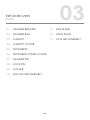
03 EXPLODED VIEW
PACKAGE CONTENTS
01.
02.
03.
04.
05.
06.
07.
08.
09.
10.
HANGER BRACKET
CANOPY
CANOPY COVER
DOWNROD STAND COVER
DOWNROD, HANGER PIN
& LOCK PIN
FAN MOTOR ASSEMBLY
FAN BLADES (3 PCS)
LIGHT PLATE
18 W LED ASSEMBLY
11.
12.
13.
14.
15.
16.
REMOTE CONTROL HOLDER
12 V BATTERY
BLADE BALANCING KIT
INSTALLATION INSTRUCTIONS
REMOTE CONTROL
RECEIVER
PARTS PACK CONTAINING:
17. EXTENSION POWER CORD
(42˝ / 106.7 CM)
3 x Wood Screws
2 x Machine Screws
3 x Flat Washers
3 x Spring Washers
2 x Star Washers
3 x Wire Nuts
1 x Blade Screw
3 x Screw Retainers

9
03
EXPLODED VIEW
DETAIL
01.
02.
03.
04.
05.
06.
07.
08.
09.
10.
HANGER PIN
CANOPY
HANGER BALL
HANGER BRACKET
LIGHT PLATE
COLLAR
FAN BLADE
LOCK PIN
FAN MOTOR ASSEMBLY
11.
12.
13.
DOWNROD STAND COVER
DOWNROD
CANOPY COVER
18 W LED ASSEMBLY

10
03
12
13
11
01
09
10
02
03
04
07
05
06
08

11
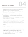
04
ELECTRICAL SAFETY
Instructions
•
01.
02.
03.
04.
Making the Electrical Connections
•
•
Read all safety information and installation instructions before
you begin to install the fan and save instructions.
All set screws of the fan must be checked and re-tightened
where necessary before installation.
To reduce the risk of personal injury, do not bend the blade
brackets when installing the brackets, balancing the blades
or cleaning the fan. Do not insert foreign objects between
rotating fan blades.
Before changing the fan direction, turn off the fan and wait for
the fan blades to stop completely.
The safeguards provided by these safety instructions and by
the separate installation instructions are not meant to cover all
possible conditions and situations that may occur. It must be
understood that common sense, caution and care are factors
which cannot be built into this product. These factors must be
supplied by the person(s) installing, caring for and operating
the fan.
WARNING: To avoid risk of electric shock, be sure to shut off
power at the main fuse or circuit breaker box before installing
To reduce the risk of injury, install the fan so that the blades are
at least 6’ 11’’ (2.1M) above the floor and at least 30’’ (76cm)
from the tip of the blades to the wall.

12
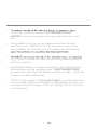
04
•
•
•
•
•
mount the outlet box marked “ACCEPTABLE FOR FAN
SUPPORT” and use mounting screws provided with the outlet
box.
The installation must be in accordance with the national
electrical code, ANSI/NFPA 70-1999 and local codes. If you
are unfamiliar with the methods of installing electrical wiring,
injury, mount to outlet box and use mounting screws provided
with the outlet box.
IMPORTANT: Before you begin installing the fan, carefully read
all information on the separate sheet “SAFETY INSTRUCTIONS”
NOTE: The fan weight is 11 lb 6 oz (5.17kg). Be sure the outlet box
you are using is securely attached to the building structure and
can support the full weight of the fan. Failing to do so can result
in serious injury.
as well as the following “Installation Instructions Steps”. If in doubt,
consult a qualified electrician.

13
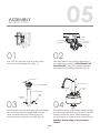
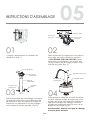
05
01
ASSEMBLY
INSTRUCTIONS
Fig. 1
Fig. 2
Mounting
Bracket
Outlet
Box
Outlet Box
Screw
Turn OFF the electric circuit at the main
fuse of circuit breaker box (Fig. 1).
02
04
Securely attach the hanger bracket to
an outlet box marked "ACCEPTABLE FOR
FAN SUPPORT" using the supplied outlet
box screws with spring washers (Fig. 2).
Fig. 4
Hanger
Pin
Downrod
Lock
Pin
Warning: Ensure wiring is not pinched or
twisted.
Thread the motor wires safety cable through
the downrod and downrod stand. Insert the
downrod into the collar. Slide hanger pin
through holes of collar and downrod (Fig. 4).
03 Fig. 3
Lock
Pin
Hanger
Pin
Downrod
Cross Pin
Hanger Ball
Remove the lock pin and take out the hanger
pin; then remove the hanger ball from the
downrod assembly by loosening the set
screw and removing the cross pin (Fig. 3).

14
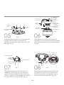
05
Cross Pin
Set Screw
Fig. 8Fig. 7
07 08
Hanger
Bracket
Slot Clip
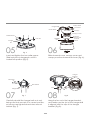
Insert and tighten the two collar screws.
Slide lock pin into hanger pin until it is
locked into position (Fig. 5).
05 06
Fig. 5
Hanger Ball
Fig. 6
Lock Pin
Collar Screws
Hanger
Pin
Safety Cable
Motor Wires
Hanger Ball
Lock Pin
Downrod
Canopy
Canopy Cover
Collar
Hanger
Pin
Downrod
Stand Cover
Slide downrod cover, canopy cover and
canopy over the downrod as shown (Fig. 6).
Hang the fan onto the hanger bracket,
and make sure the slot of the hanger ball
is aligned with the clip of the hanger
bracket (Fig. 8).
Carefully reinstall the hanger ball onto rod,
being sure that cross pin is in correct position,
set screws are tightened and wires are not
twisted (Fig. 7).

15
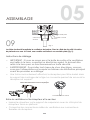
05
Fig. 9
ASSEMBLY
09
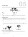
The safety cable prevents the fan from falling. Secure the safety cable to the ceiling joist with
a wood screw, star washer and flat washer (Fig. 9).
Safety
Cable
Star Washer
Wood
Screw
Flat Washer
IMPORTANT: If you are not sure if the electrical outlet box and fan are
grounded, contact a licensed electrician for advice. They must be
grounded for safe operation.
WARNING: To avoid possible electric shock, be sure electricity is turned
off at the main fuse box before wiring.
Wiring Instructions
•
•
•
Leave unconnected and do not cut.
VIEW AFTER INSTALLATION
Insert receiver into hanger bracket with the flat side of the receiver
facing the ceiling.
Connect the male connectors from the fan to the female connectors
from the receiver.
Between Fan & Receiver & Mains
•
•
Once the connection has been made, the receiver inserts into the
down rod hanger bracket. The canopy comes up to cover the receiver
and bracket.

16
05
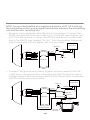
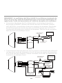
Receiver to House Supply Wires Electrical Connections: Connect the
WHITE wire (Neutral) from the outlet box to the WHITE wire marked “AC
in N” from the receiver. Connect the BLACK wire (Hot) from the outlet
box to the BLACK wire marked “AC in L” from the receiver. Secure all
wire connections with the plastic wire nuts provided.
•
•
NOTE: Fan must be installed at a maximum distance of 40’ (12.2 m) from
the transmitting unit for proper signal transmission between the transmitting
unit and the fan’s receiving unit.
Connect the ground wire (yellow & green or bare copper) from the
outlet box to the ground wire of hanging ball and the ground wire of
hanger bracket and the receiver ground wire. Secure wire connection
with the plastic wire nut provided.
RECEIVER
BLUE
WHITE
GREY
RED
YELLOW
YELLOW & GREEN
OUTLET BOX
HOT
AC IN N
AC IN L
YELLOW & GREEN
RECEIVER
BLUE
WHITE
GREY
RED
YELLOW
YELLOW & GREEN
OUTLET BOX
YELLOW & GREEN
YELLOW & GREEN
YELLOW & GREEN
YELLOW & GREEN
GROUND
AC IN N
AC IN L
HOT
GROUND
GROUND
NEUTRAL
NEUTRAL
WIRE NUT
WIRE NUT
WIRE NUT
WIRE NUT
WIRE NUT
HANGER
BRACKET

17
05
ASSEMBLY
11
10
Hanger
Bracket
Hanger
Bracket Screw
Canopy
Canopy
Screw
Key
Hole Slot
Canopy
Cover
Fig. 10
Fig. 11
Blade
Screw Retainer
Blade Screw
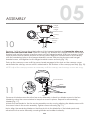
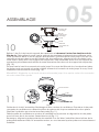
Remove six blade screws from the fan motor assembly. Attach two blade screws to the fan
blades by using the screw retainer to keep the screws in place. Repeat for all remaining
blades (Fig. 11).
NOTE: Adjust the canopy screws as necessary until the canopy and canopy cover are snug.
Attach the fan blades to the fan motor assembly one by one by aligning the blade screws with
the screw holes in the motor assembly. Tighten screws securely (Fig. 11).
Note: Align the remaining blades so that they slot into the blade lip of the blade previously
attached to the motor assembly, ensuring blades are installed correctly.
Push up the canopy cover until the screw heads engage to the slots on the canopy cover
and rotate the canopy cover until it is attached to the bottom of the canopy securely (Fig. 10).
Remove 1 of the 2 screws from the bottom of the hanger bracket and loosen the other one
half a turn from the screw head. Slide the canopy up towards the hanger bracket and place
the key hole on the canopy over the screw on the hanger bracket, then turn canopy until it
locks in place at the narrow section of the key holes. Align the circular hole on the canopy
with the remaining hole on the hanger bracket, secure with previously removed hanger
bracket screw, and tighten both hanger bracket screws securely (Fig. 10).

18
05
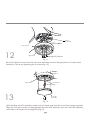
12
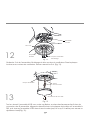
Remove 3 light kit screws from the fan motor assembly. Attach the light plate to the fan motor
assembly. Secure by tightening the 3 screws
(Fig. 12).
13
Fig. 12
Fig. 13
Light Plate
Round Hole
Light Kit Screws
Motor
Assembly
Connection
Plugs
Light Plate
18 W LED
Assembly
While holding the LED assembly under your fan, firmly snap the wire connection plugs together.
Align the two arrow marks on the light plate and the LED assembly, then turn the LED assembly
clockwise until it stops to ensure tight fit (Fig.13).

19
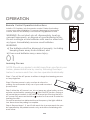
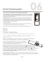
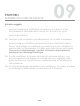
06
OPERATION
on any single fan.
power switch.
Step 3: After the AC power is on, do not press any other button on the
remote control before pressing the (FAN ON/OFF) button. Doing so
will cause the procedure to fail. Within 30 seconds of turning the fan’s
AC power ON, press and hold the button for 5 seconds to enter the
learning function.
Once the receiver has detected the set frequency, the light will blink
two times when the pairing is complete.
Step 4: Repeat steps 1, 2, and 3 with each fan to ensure each fan can
be operated by the paired remote only, and without interfering with
each other.
Learning Process
01
Remote Control Operation Instructions
WARNING: Do not short-circuit, disassemble, heat up,
connect improperly, or dispose of used batteries in fire.
Do not recharge or mix batteries with used or other batt-
ery types. Immediately remove used batteries.
WARNING:
a) The batteries shall be disposed of properly, including
keeping them away from children; and
b) Even used batteries may cause injury.
Install a 12 V battery into the remote control. Fasten the battery
cover screw after installation. To prevent damage to the remote
control, remove the battery if not used for long periods of time.
Step 1: Turn off the AC power to all fans to begin the learning process
Step 2: Restore power to only one fan at a time for
pairing; the rest remain off by use of your wall-mounted
NOTE: Should you desire to install more than one fan in your
home, please install one by one by following the steps
below to ensure each fan can be operated individually:

20
06
•
•
•
•
•
•
•
Fan on/off. The fan memory function will store the current setting for the next
time the fan is in use.
2. 1,2,3,4,5,6 buttons:
These six buttons are used to set the fan speed as follows:
1=low speed 2=medium low speed
3=medium speed 4=medium high speed
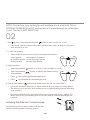
3. Light functions
Press to increase the desired light level.
Press to decrease the desired light level.
4. Fan reverse button (Must be pushed when the fan is in operation.)
This allows you to set your air conditioner on a higher setting without affecting
your comfort.
(Clockwise direction) An upward air flow moves warm air off the ceiling. This
allows you to set your heating unit on a lower setting without affecting your
comfort.
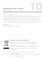
Installing The Remote Control Holder
02
• temperature.
NOTE: On start-up your ceiling fan will oscillate back and forth. This is
NORMAL OPERATION for DC ceiling fan as it goes through its calibration
cycle. The fan is NOT DEFECTIVE.
1. Fan button. Press and release the button to turn the fan on or off.
5=high speed 6=extra high speed
Press and release button one time to turn the light on or off.
Press and release button to select the desired colour
(Counter-clockwise direction) A downward air flow creates a cooling effect.
Attach the remote control holder with the two
remote control holder mounting screws.
La page est en cours de chargement...
La page est en cours de chargement...
La page est en cours de chargement...
La page est en cours de chargement...
La page est en cours de chargement...
La page est en cours de chargement...
La page est en cours de chargement...
La page est en cours de chargement...
La page est en cours de chargement...
La page est en cours de chargement...
La page est en cours de chargement...
La page est en cours de chargement...
La page est en cours de chargement...
La page est en cours de chargement...
La page est en cours de chargement...
La page est en cours de chargement...
La page est en cours de chargement...
La page est en cours de chargement...
La page est en cours de chargement...
La page est en cours de chargement...
La page est en cours de chargement...
La page est en cours de chargement...
La page est en cours de chargement...
La page est en cours de chargement...
La page est en cours de chargement...
La page est en cours de chargement...
La page est en cours de chargement...
La page est en cours de chargement...
La page est en cours de chargement...
La page est en cours de chargement...
La page est en cours de chargement...
La page est en cours de chargement...
La page est en cours de chargement...
La page est en cours de chargement...
La page est en cours de chargement...
La page est en cours de chargement...
-
 1
1
-
 2
2
-
 3
3
-
 4
4
-
 5
5
-
 6
6
-
 7
7
-
 8
8
-
 9
9
-
 10
10
-
 11
11
-
 12
12
-
 13
13
-
 14
14
-
 15
15
-
 16
16
-
 17
17
-
 18
18
-
 19
19
-
 20
20
-
 21
21
-
 22
22
-
 23
23
-
 24
24
-
 25
25
-
 26
26
-
 27
27
-
 28
28
-
 29
29
-
 30
30
-
 31
31
-
 32
32
-
 33
33
-
 34
34
-
 35
35
-
 36
36
-
 37
37
-
 38
38
-
 39
39
-
 40
40
-
 41
41
-
 42
42
-
 43
43
-
 44
44
-
 45
45
-
 46
46
-
 47
47
-
 48
48
-
 49
49
-
 50
50
-
 51
51
-
 52
52
-
 53
53
-
 54
54
-
 55
55
-
 56
56


NOMA Cassian Outdoor Le manuel du propriétaire
- Catégorie
- Ventilateurs ménagers
- Taper
- Le manuel du propriétaire
dans d''autres langues
- English: NOMA Cassian Outdoor Owner's manual
Documents connexes
-
NOMA Harper 4-Blade 6-Speed Outdoor Le manuel du propriétaire
-
-
-
-
-
-
-
Autres documents
-
Progress Lighting P250000-081 Guide d'installation
-
 Kichler Lighting Jade 300030 Manuel utilisateur
-
Modern Forms FR-W2006-62L-MW Guide d'installation
-
 Lucid FR-W2304 Matte Black Blades Downrod Ceiling Fan Manuel utilisateur
-
Kichler 310155SBK Manuel utilisateur
-
-
Progress Lighting P250030-009 Guide d'installation
-
-
 PROGRESS LIGHTNING P250002-143-30 Mode d'emploi
-


