MULTIPLEX Alpina Le manuel du propriétaire
- Catégorie
- Jouets télécommandés
- Taper
- Le manuel du propriétaire

il
-
//
//
///
Bauanleitung
Building instructions
lnstructions
de
montage

FLUGGESCHWINDIGKEIT
E
uJ
v
o
ol
z
+2
o
a
trl
o3
v
z
vt4
V5
VS min=
O,37
m
/ sec bei G/F
4opldm- und
VH
8,5 m/sec
Emax=25,7
bei G/F 60
p/dm'und
vH
13,2
m/sec

Bauanleitung
Bltte bson Sle
vor Baub€glnn unbedlngt dlese
gauanleltung,
Vergleichen
Sie die einzelnen
Bauteile mit der Stückliste und dem Bauplan.
Sie
vermeiden
damit Baufehler und
verkülzen
die
Bauzeit.
Zweckmäßigerwoise
wird beim Bau des,,Alpina"
folgende Reihenlolge eing€-
halten:
O
Fertigstellung von Höhen- und Seilenruder
a Anbau der
Buder
an den
Rumpl
a Einbau der
Tragflügelaufhängung in
den
Rumpf
a Einbau der Spsrrholzteile
in
den
Rumpf
a
Kabinenhaube mit Verriegelung
O Fertigstellung der
Tragflüge
a Bespannungs- und
-
falls
gewünscht
-
Lacki€rarbgiten
O
Fernsteuerungseinbau und
Justierung
Für die anfallenden
Verklebungsaöeiten können folgende Klebsstoffe ver-
wendet werden:
Styropor
-
Holz Weißleim, Devcon,
Uhu-por
und alle
sonstigen
für Styropor zugelassenen Klebslofie.
Keine
Lö-
sungsmittel-haltige
Klebstotte veMenden. lm
zweifelslalle an einem Styroporrest Vorversu-
che durchtühren.
Holz
-
Holz Weißleim, Zacki, Uhu-hart, Devcon undsonstige
Holzkleber.
-J
GfK
-
Holz
Uhu-plus,
Devcon, 5-Minuten-Klebsharz,
GfK
-
Metall sonslige
Klebstoffe
auf
Epoxidharzbasis.
Vorarbelten an den
Flügeln
AlsVorarbeit an den
Flügelnwerden die Stahlzungen 22 unddie Haltestifte 29
in
die
Flügelwurzel eingeharzt. Hiezu
muß
Uhu-plus oder ein
anderer hoch-
wertiger Kleber
verwendet werden. Aut keinen Fall 5-l\,linuten-Kl€b€harz
wie
Devcon oder ähnliches
verwenden!
Die Stahlzungen
probeweise
in
den
Flügel einstecken; diese dürfen
nicht
länger als 90 mm überstehen. Slahlzung€n
entletten. Flügel schräg
-
nach
Möglichkeit senkrecht-stellen
und in die Vertiefung in der Flüg€lwurzel Kleber
einlüllen.
Mit dünnem Draht
Kleber in
den
Spalt sinrühren. Stahl einsl€cken,
Uberstand
prüfen
und Vertiefung bündig mit Kleber autfüll€n.
Haltestifte 29
ebenlalls
-
Uberstand
hier 13 mm
-
einkleben.
Flügel zum Aushäden über
Nachl senkr€cht stellen.
Höhen- und Seltenruder
Die Fertigstellung
der Höhenruder
1
beschränkt sich auf das Anbringen der
Randbogen 2. Nach Bauplan ankleben und verschleilen. Darauf achten,
daß
hierbeidas
aus Gewichtsgründen nur 1 mm dicke Furnier
nicht
durchgeschlii
fen wird.
An
das Seitenruder 3 oberen
(4)
und unteren
(5)
Klolz anleimen. B€i Klotz 5
daraul achten, daß er so weit als möglich zur Stirnseite des Ruders hin
angeleimt
wird. Klötze mit
der Stirnseite des
Buders
bündig schleifen.
Leiste 6 vor Stirnseite des Ruders kleben. Nach dem vollständigen Aushärten
sämtlicher Verleimungen die
beiden
Klötze und
die
Leiste bündig
schleifen.
Wedsrum darauf achten, daß das Furnier nicht durchgeschliffen wird. Di€
beid€n Klötze nach Zeichnung verrunden. Die Vorderseite wird
-
um dem
Ruder
Bewegungstrgiheit
zu
geben
-
nach Z€ichnung
im Winkel von
ca.
15
Grad zweiseitig
angeschrägt.
Dazu mit Filzstift Mittellinie anzeichnen und
Leiste bgschlgifen. Zum Schluß
-
um scharfe Kantgn zu €rhallen
-
mit
fein
eingeslelllem
Balsahobel nachziehen.
x
ö
9,

RumDf
Jetztkönnen
das
sovorbereilete
Leitwerk bzw.
Ruder an den
Rumpfangebaut
werden.
Dazu wird zuerst
der Höhenleitwerks-Pendelhebel
7 in
die
Seiten-
llosse eingebaut.
Dieser Arbeit
ist besondere Sorglalt
zu
widmen, da von der
Leichtgängigkeit
und Exaktheit
dieses
Einbaus das spätere
Flugverhalten
beeintlußt
wird.
(Abb.
1)
Lagermarkierung
der Seilenllosse
mil
o
4 mm aul beiden
Seiten aufbohren
Sichelförmige
Aussparung
fÜr den hinteren
Leitwerksdraht
vorbohren und
mal
einer
Halbrundfeile
exakt
nach
der
Markierung
bearbeiten
Pendelhebel
7 aul die Achse I
aufstecken.
Lagerscheiben 9
nach Zeichnung
ebenfalls
aufstecken;
dabei
zeigen die Röhrchen der
Scheiben
nach außen.
Den so
vorbereileten
Pendelhebel mit
Lagerung in die Seitenflosse
einstek-
ken, dabei
noch
kein Harz angeben.
Höhenruder
unter VeMendung
der
beiden Stahldrähte
10
aufstecken.
Stahldrähte
an den
Enden leicht wellig
biegen,
damit sie
in den Rudern sicher
halten. Das
Höhenruder
muß im
rechten
Winkel zur Seitenflosse
slehen.
Ebenlalls daraul
achten, daß die
Wurzelrippen
der Höhenruderam
Seitenruder
anliegen. Die
Bohrungen
in
der
Seitenflosse
-
falls
erforderlich
-
mit einer Rundteile
nacharbeiten
Pendelhe-
bel wieder
ausbauen.
Pendelhebel,
Achse und
Lagerscheiben
wie im Bauplan dargestellt
unter
Zugabe
von wenig 5-Minuten-Klebeharz
außerhalb des
Rumpfes zusammen-
bauen.
Darauf
achten, daß
kein Harz an den
Pendelhebel
gelangt
Zwischen
Hebel
und Lagerscheaben
muß auf beiden
Seilen ca. 0,5
mm Lufl sein,
damit
sich
der
Hebel sicher bewegen
läßt. Nach dem
Aushärten des
Harzes Beweg'
lichkeil überprüfen;
falls
notwendig, nacharbeiien.
Aul einen Stahldrahl
12
eine
Lothülse
13 löten. Für eine sichere
Verlötung
'empliehlt
es sich,
den Draht
im Lötbereich zuerst
blank zu schleilen
und dann
wellig
zu biegen, so daß
ergerade
noch in die Löthülse
eingeschoben
werden
kann. Sorglältiges
Arbeiten beiallen
derartigen
Verlötungen trägt
zur späteren
Flugsicherheit bei!
Gabelkool
14 aul die
Löthülse bis
zum Anschlag auldrehen
und
mit
einem
Tropfen
Kontaktkleber
gegen
Verdrehung sichern.
Gabelkopt
in den
Hebel
einklinken.
Die
Einhängpunkte sämtlicher
An' und Umlenkungen
des
Modells
sind
im Bauplan
lür MULTIPLEX-RC-Anlagen
dargestellt.
Bei VeMendung
anderer
Fabrikale sind
die Empfehlungen
der
jeweiligen
Hersteller
zu be-
achten.
Seitenflossen-Endleiste
15 in die Seitentlosse
einpassen
Dazu oberes
und
unteres
Ende der
Leiste entsprechend
der Seitenllosse
verrunden.
Mit dem
schon
lertiggestelllen
Seilenruder
den Verlauf der
konischen
Endleiste über-
prülen. Ruderund Flosse
müssen- um unnötigen schädlichen
Widerstand
zu
vermeiden
-
an der Stoßstelle
den
gleichen
Dickenverlauf
autweisen
Falls
notwendig,
nacharbeiten.
Pendelhebel nochmals
einbauen, dabei
Draht
in
den
8o',vdenzug einlühren
und Leichtgängigkeit
und
Funktion überprÜfen
Jetzt
kann das
Pendelhebellager endgültig
eingeharzt
werden
Dazu Rumpf
aut der
Bauunterlage
mil exakt senkrechter
Seitentlosse
lixieren
An die
Lagerscheiben
des
Hebellagers aoßen
Harz angeben,
Drahl
in
den
Bowden-
zug einschieben
und Hebellager
in der Seitenflosse
positionieren.
Unterlag-
scheiben
1 1 mit Harz versehen
in die Aussparungen
der Seitenflosse
auf der
Außenseite
einlegen.
Ausrichten und
Höhenruder
mit den Lagerdrähten
anmontieren.
Höhenruder mit etwas
Abstand von der Seitenflosse
positionie'
ren. damit ein
Verkleben durch ausquellendes
Harz vermieden
wird.
ln die Seitenflosse
die
Endleiste 15 einlÜhren
und rnit
Klebeband
tixieren;
Leiste 15
jedoch
noch nicht einkleben.
Höhenruder ausrichten,
nochmals auf
rechten
Winkel zur Seitenflosse
überprülen.
Höhenruderdurch
Unterlegen
bis
zur vollsländigen
Aushärtung des
Harzes sichern.
Leichtgängigkeit
des
Ruderantriebes überprÜfen
und lalls
notwendig nachar'
beiten.
Das Ruder
muß sich über den
gesamten RudeMeg leicht und ohne
zu
streilen bewegen
lassen. Höhenruder abmontieren.
Überstehende
Teile der
Pendelhebel-Lagerung
mit der
Flossenaußenseite
bündig
schleifen;
dabei vorsichtig arbeiten
-
eventuell Umgebung
abkleben
-
damit die
Oberlläche der
Flosse nicht beschädigt
wird.
Vom Cockpit
aus die
Bowdenzug-lnnenseele
16 über den Stahldraht
schie'
ben. DIG Bowdenzug-lnnenseele
dart nlcht
mil
dem
Stahldraht
verklsbt
werden, da sonst
Leichtgängigkeit
nicht mehr
gewährleistet ist.
Es
lolgtder Einbau
der Seitenflossen-Endleiste
15.
Vorderen Einkleben
in die
Seitentlosse
muß noch die
Durchführung
für
die Seitenruder-Anlenkung
nach
Zeichnung
angebrachl
werden. Ende des
Bowdenzuges ausmessen
und
aul
die Außenseite
übertragen.
Nach Zeichnung eine
Durchführung
vorbohren
und
sauber
ausleilen.
Endleiste
15 mit Uhu-plus oder
einem anderen
hochwertigen
Klebeharz
einkleben.
Flosse mit
geeigneten Beilagleisten
(liegen
dem
Baukaslen
nicht
bei) und
kleinen Schraubzwingen
bis zum Aushärten
der Verklebung
zusam-
menpressen. Hierzu
noch ein kleiner
Trick: kleben Sie die
Beilagleislen
vor
dem
Einharzen der
Endleiste
mit Doppelklebeband
in
entsprechender
Posi-
tion außen an die Seitenflosse.
Das Anbringen der Schraubzwingen
wird
dadurcherleichtert.
FlossedurcheinenBlickvonobenauf
Verdrehungprüfen,
nach Bedarl Zwingen
wieder lösen und
neu
ausrichten.
Die
Flosse muß
exaK
mit der Rumpfachse
fluchten!
Flossenhinterkante
bündig schleiten.
Dann
-
wie
schon
bei der Rudervorder-
kante
-
nach Zeichnung
zweiseitig anschrägen.
Ruderscharniere anbringen.
Mit schartem
Balsamesser entsprechende
Schlitze einschneiden.
Ole Schar"
nlere werden ersl
nach dem Bespannen
des Leitwerks eingeklebt.
Es
folgt
die
Anlenkung des Seilenruders.
Für
das
Ruderhorn 18 in entspre'
chender
Position nach Zeichnung
mit scharfem Balsamesser einen Schlilz
einschneiden.
Ruderhorn
mit Devcon einkleben.
Dazu
Umgebung
des Schlit'
zes mit Klebeband
abkleben, damil das
Leit,,verk durch ausquellendes
Harz
nicht verunreinigt wird.
Nach
dem
Aushänen
Klebeband entfernen.
Stahldraht
12
nach Zeichnung biegen und durch
die Seitenruderdurchführung
in
den
Bowdenzug einführen.
Drahtende leicht
nach
unten
biegen, dadurch
wird das abgewinkelte
Ende unter Spannung
im Ruderhorn
gehalten.
Eine
weitere Sichefung erübrigl sich.
Damit istderAnbau
von Höhen
-
und Seitenruder
abgeschlossen.
Esfolgt der
Einbau der
Flügelaulhängung und
Rumptuerstärkung in den Bumpf.
l\rarkierungen
für
die
Stahlstilte des
Flügels in der FlÜgelanformung
des
Rumpl€s
mit
o
3 mm bohren. Otlnungen
lür das Flügelmitlelstück
nach den
Markierungen vorbohren
und ausleilen.
Die Bohrungen für die Ouerruder
-
und Störklappenanlenkung
vom Flügel aul den
Rumpf
tjbedragen
und mit o 8
mm bohren. Es empfiehlt
sich, diese
Bohrung mit einem
kleineren Bohrsr
vorzunehmen und
mil
einer
Rundfeile auf das
Endmaß aulzureiben; dadurch
wird eine
Beschädigung des Rumpfes
vermieden.
Rumptuerstärkung
19 in den Rumpl einpassen
und mit Uhu-plus einlein"^
Unbedingt darauf
achten, daß der
Rumpl nicht auselnandergedr\-.
wird, da sonst der
Flügel elne unenvünschte
Plellung €rhäll.
Die beiden
Stirnllächen der
Flrigelanformung
müssen absolut
paralell
bleiben.
Falls eine
Schieblehre
vorhanden. nachmessen.
Gemessen
wird in
derMine
der Nasen-
radien und an der Endfahne.
Es folgt der Zusammenbau der
Flügelaufhängung,
die aus den
Teilen 20 bis
28 besteht
(Abb.
2). Zuersl
wird
das
verschiebbare
Klemmstück
(Teile
23
bis
28) zusammengeschraubt.
Dabei darl das
Eindrücken des
Hohlniets in die
Klemmen-Rückwand
24 unter keinen Umsländen
vergessen
werden; ohne
ihn ist eine einwandfreie
Klemmung nachl
gewährleistel.
Zusammengebautes
Klemmstück
Über beide
Vierkant-Messingrohre
20
schieben.
Achtung!
Oie
Klemmschraube
26 darf
nlemals ohne
elnge
steckte
Slähle angezogen
werden !
Kulissen
21 tiberschieben,
darauf
achten, daß
an der
später eingebauten
Flügelaufhängung
der rechte
Flügelstahlvor
den
linken FlÜgelstahlzu
liegen
kommt;die
Markierungen
am Rumpf
und die
Aufnahmekästen
in den FlÜgeln
sind entsprechend
gearbeitet. Falls dies
nicht
beachtet
wird, ist ein späterer
zusamrnenbau des
l\,lodells nicht möghch.
Jetzt
muß
über die
V-Stellung der
Flügel entschieden
werden Bei den
Prototypen
haben sich
3,5 Grad
pro
Flügel bewährt
FÜr Einsatz
im Flachland
empfehlen
wir lür den übeMiegenden
Thermik-Kreisflug
4,0 Grad
pro
Flügel
Unter3,5
Grad
pro
Flügeltritt ein
größeres
Schieben des
Modells-
das durch
entsprechend
widerstandserhöhende
Ruderkorrehuren
ausgeglichen
wer-
den
muß
-
ein,
über
4
Grad
pro
Flügel wird das
Modell eigenstabiler
und
reagiert nicht
mehr so
prompt
aul die
Ruder. Dazu
noch ein
Hinweis:
In
den
Auß;nflüqel
des
'Alpina"
ist eine zusätzliche
V'Stellung
eingoarbeilet.
Bei

einem
Blick
über die
Nasenl€iste
des Flügels
werden Sie
bemerken,
daß
das
zweite
Trapez
leicht
nach oben
gebaut
ist.
Dies
ist Absicht
und
hat sich
bei
vielen
Vorgängern
und
Prototypen
des
,,Alpina"
bestens
bewährt
Die
V-stellung
des
Flügels
wird durch
den
Absland
der
Kulissen
zuernander
bestimmt.
Dabei
sind:
76 mm
=
3,0
Grad
Pro
Flügel
65
mm
=
3,5 Grad
Pro
FlLigel
57
mm
=
4,0 Grad
Pro
Flügel
50
mm
=
4,5 Grad
Pro
Flügel
Aul den
Messingrohren
Mine anzeichnen
und
Kulissen
im
gleichen Abstand
zur
lritte
und
iln entsprechendem
Abstand
zueinander
positionieren
Mit
Klebeharz
(Uhu-plus)
fixieren oder
-
noch besser
-
verlöten
Hierbei
aufge-
schobenes
Klemmstück
zur Serle
rLlcken
Es
lolat das
etqentllcne
Ernpassen
der
Flügelauthängung
In
den
Rumpf'
das
mit S;glall
du;chgeluhrl
werden
muß Dazu
werden
berde
Flügel
benötigt
Vorbereitete
Flügelaufhängung
in den
Rumpl
eintügen
und
beide
Flügel
aufstecken.
Dab;
kann
-j;naah
gewählter V-Stellung
-
ein
Nacharbeiten
der
Aussparungen
am
Rumpf
nach unten
über
die angezeichnete
Markierung
hinaus
notwendig
werden
Überorüfen
Sre die
Positlon der
FlLigel am
Rumpf.
Diese
rst
richlig' wenn
Flüg;lprofrl
und
Flugelanformung
am
Rumpl
genau übereinstimmen
Arbeiten
Sie"aie
Aussparung
tür
die
Flügelaufhängung
so
lange
nach, bis
dies der
Fall
ist.
Falls die
hinteren
Bohrungen
für den
Haltestitt
nachgearbeitet
werden
müssen,
empfiehll
sich
lolg€ndes
Verlahren:
Bohrung so
lange
nacharbeiten'
bis die
Flügel
einwandfrei
an den
Rumpf
passen
Die
Bohrung
kann später'
wenn das
FlÜgelmittelstück
eingeharzt
ist,
abgeklebl
und
mit Klebeharz
von
,1
ausgefüilt
werden
(Devcon) Nach dem
vollständigen
Aushärten
(über
\"c60
Bofrrunq
in richtiger
Position
wiederholen
Wenn beide
Fltigel
an den
Rumpl
passen' kann das
Flügelmittelstück
-
mit
autgeschobenem
KlemmstÜck
-
mit einigen
Troplen
Devcon
oier 5-l\'linuten-
Kle"beharz
in den
Rumpl
eingeheftel
werden.
Aul
keinen
Fall das
ganze
Mltlelstück
mit diesem
Hatz einkleben,
diese
Verklebung
würde aul
die
Dauer
nichtden
Belastungen
standhalten.
Nach dem
vollständigen
Aushärten
der
Hettung
Fltlgel
vorsichtig
abziehen
Flügelanformungen
im Bereich
des
FlÜgelmittelstücks
außen
mit Klebeband
aokieben.
Rumpt aul
die Seite
legen und
fixieren.
ln den
Bumpf
um
das
Mittelslück
angedicktes
Klebeharz
(Uhu'plus)
geben; es
kann hierzu
auch
Laminierharz
;it Microballoons
verwendet
werden.
Der Rumpf
darf
bis zum
vollständioen
Aushärten
des
Harzes
nichl bewegt
werden,
damit
kein Harz
in
die
Messi;grohre
eindringen
kann
Anschließend
mit der
Gegenseite
ebenso
verfahren.
Wichtiger
Hinwels!
Die
in den
Rumpt
eingelegten
Kunststotf'Bowdenzüge
sind
hitlzeempfindlich.
Ebenso sollte
die
Einfärbung
des
Rumpfes
keinen
höheren
Temperaturen
ausgesetzl
werden.
Deshalb
Rumpl
zum
Aushärten
von
Klebeharien
nicht höheralsca.5O
Grad
erwärmen
! FlLlgelanformung
plan
schleifen.
Damit
isl der
Einbau
der
Fltjgelaufhängung
abgeschlossen
Es
lolgt der
Einbau von
Ruderrnaschinenbrettern
und Spanten
-ldermaschtnenbretler
30 und
31
zum Elnbau
vorberelten
ln
den
Bumpl
änpassen
und
Kanten enlsorechend
der
Rumpfwand
anschrägen
lm Rumpf
Lage sämtlicher
Sperrholzteile
anzeichnen
und
Rumptwand
autrauhen'
Falls eine
l\4tJLTIPLEX-Fernsleuerung
zum Einsatz
kommt,
können die
Aus'
sparungen
tLirdie Servos
direktvom
Bauplan
übernommen
werden
Wirdeine
iernste'uerung
anderen
Fabrikats eingebaut,
so
verwenden
Sie
deren
Einbau-
material
mit
veränderten
Maßen
lür die
Aussparungen
lvlultiplex-Servos
mittels
Servo-schnellbelestigungen
Best
Nr' 8
70 70
(lie'
qen
äem
Baukasten
nicht bei)
auf den
Rudermaschinenbrettern
betestigen
ialls eine
F-schleppkupplung
eingebaut
werden
soll,
berücksichtigen,
daß
das
Servo
hierlÜr
durch
Unterlage
eines
Sperrholzresles
3
mm erhöhl
e'nge'
baut
werden
muß.
Zuerst
wird
das Querruder-/Störklappenservo-Brett
30
in den
Rumpf
einge'
O"ut.
Ut
a"ta"n
richtige
Position
zu ermitteln,
werden
in die beiden
Flügel
provisorisch die
Anlenkungs-stahldrähte
tür Ouerruder
und
Klappen
zusam'
;en
mit den
Bowdenzug-lnnenseelen
so
eingesteckt,
daß
sie etwa
30
mm aus
der
Flügelwurzel
herausragen.
Flüoel aul
den
Rumpt
aulstecken
und
Rudermaschinenbrett
in den
Rumpf
einichieben.
Brett so
iustieren,
daß
die aus
den
Flügeln
herausragenden
Drähte
exakt
auch
di;
Einhängpunkte
der
Rudermaschinenhebel
zeigen
Beachlen
Sie
dabei
auch,
da8 der
Ouerrudermaschinen-Hebel
in der
lm
Bauplan
dargestellten
Weise bearbeitet
werden
muß
Dies bewirkt,
im Zusam'
me;spielmit-der
Umlenkung
und der
Anlenkung
der
Ouerruder,
die srforderlF
che
difierenzrerung
der
Ruder'
Es erglbt
srch
der
-
aus aerodynamischen
Gründen
-
notwendige
größere
Ausschlag
nach oben
als
nach
unten
uas
Verhältnis
sollte
dabei
ca
4
nach oben
und
/3
nach unten
betragen'
Eine einfachere
und
exaktore
Anlenkung
eftalton
Sie
i€doch'
wenn Sie
den
säro"otüä*rt"o"r
Best.
Nr' 08
5211
-
einen
besonders
tür diessn
zweck
konstruierten
Hebel
-
verwenden.
lst das
Rudermaschinenbrstt
optimal
positionied, wird
es-
wie schon
beider
Flügelaufhängung
-
mit einigen
Troplen
Klebeharz
lixiert
Soll
eine
F-schleppkupplung
eingebaut
werden,
ist der
Spant
32
an der
Markierung
mit s 3
mm zu
bohren
Rudermaschinenbrett
31
zusammen
mit Spant
32 und
Halbspant
33
in den
Rumot einoassen,
ausrichten
und
mrt
einigen
Tropfen
Klebeharz
rxlelen
u€r
Rumpf
darf
dabei
nicht
auseinandergedrÜckt
werden'
Vor dem
endgültigen
Einharzen
sämtlicher
Sperrholzteile
überprülen
Sie:
a Zeigen
die
Anlenkungsdrähte
der
Flügel
exakt
auf
die Servoab-
triebshebel?
a lst
das
Budermaschinenbrett
31
waagrecht
und
in richtiger
Position
eingebaut?
a Wurde
der
Rumpt
durch
die Spanten
und
Rudermaschinenbrener
-
auseinano",geOiilctt?
Dies
kann
durch
Aullegen
del
vom und
rrinien
angeächragten
(siehe
Bauplan)
Kabinenrahmen-Grund-
platte
überprütt
werden.
a
Können
Akku
und
Emplänger
leicht
ein
-
und
ausgebaut
werden?
Fatls ertorderlich,
nacharbeiten.
Sämlliche
Sperrholzleile
mit Uhu'plus
oder
gpoiiäf'"ta
mit
Microballoons
einharzen
Hierbei
selbstverständlich
zuvor
Rudermaschinen
ausbauenl
Nach dem
vollständigen
Aushärlen
der
Verleimungen
werden
die
Bowden-
.uo"
rJiior,""
-
""i
seitenruder
In die
richtige
Positron
gebrachl
Bowden-
t"ir,"rt"i
s8
mil Bohrung
@ 3
mm
versehen
und
aul
die
züge
autlädeln
Äri"it"a"tin"n
wieder-ernbauen
Die
Halter
mit den
zügen
so
an
den
ftaßsoant
Sg
reimen, daß
die
Stahldrähte
exaK
auf die
EinhängepunKe
an
aän ö!tä"or""ott'"oeln
zeigen
Bowdenzug
in die
Durchlührung
der
Halter
einleimen.
Falls
eine
F-schleppkupplung
eingebaut
werden
soll'
kann dies
in der
im
äärpr"n
o"gä"t"ili.;"
weise
ätogän
oiese
nrt
d€r
Kupplung.hat.sich
-
nicht
iui"tt in|."t
-eint""t't
"it
wegen
-
schon
tausendlach
bewährt'
ln die
Rumotsprtze
wird in der
im Bauplan
angegebenen
Position
ein Schlitz
von maximal
2
x 4
mm Länge
eingeleilt
Dazu
mil
feinslem
tsohrer
vomonren
""ä
s"r'fit.
mit
teiner Schlüssetieile
in Fom
teilen
Führungsrohr
39
der
Äuaofr,ontu,
anpassen
und
durch
den
vor
dem
Einbau
gebohrten Spant
"""ri"".
irpOrisioiaht
nach
zeichnung
abkröplen
und
montieren
Der
Drant
läutt
teiifrter'
wenn
erdem
Fuhrungsrohr
gemäß leichtvorgebogenwrro
Führunosrohr
mit zwischen
die
Rumpfwand
und
Rohrgeklemmtem
Aola[nolz
fiiierenlDer
Kupptungsdraht
mußgenau
in der
Mitte
des
Schlilzes
erschelnen
Führungsrohr
zusammen
mit einigen
Holzabfällen
einharzen
Kupplungsdraht
auf die
richtige
Länge kürzen
Draht
in das
innerste Loch
der
Servoabiriebsscheibe
einhängen
und
Rudermaschine
-
wie im Bauplan
dar'
gestellt
-
genau
auf
iilitte stellen.
Draht so
lange
kürzen, bis das
Ende des
Drahtes
im
Kupplungsschlitz
sichtbar
ist Funktion
überprÜlen.
Es folgt der
Bau der
Kabinonhaube.
Teile 34
bis 36
nach Zeichnung
anscirä-
gen
und auf dem
Bumpf
zusammenpassen
Die
Außenkontur
der
Teib
;ntsprechend
dem
Kabinenverlaut
ebentalls
grob
vorarbeilen.
Teile
-
mög'
lichst aul
dem
Bumpl
-
miteinander
verloimen Um
gin
Verkleben
mit dem
Rumpfzu
vermeiden,
wird
der Rumpl
hierbeimit
Haushaltfolie
oder ähnlichem
abgedeckt.
(Abb.
3).

Kabinsnhaube
41 entlang der
Markierung
vorsichtig
ausschneiden
Ausge-
härteten
Kabinenboden
endgültig
auf
Verlaul
der Kabinenhaube
schleifen
und
Kabinenhaube
einpassen.
Die
Kabinenhaube
soll sich
genau
in den
Rumpf-
verlaul einlügen.
Vor dem
Aufleimen
der
Kabinenhaube
wird der
Kabinenrahmen
-
falls
gewünscht
-
lackiert
oder
mit Folie
bekl€bt
Das
Verkleben
der
Kabinenhaube
mit dem
Rahmen
ist
mit Kontaktkleber
vorzunehmen.
Dabei wird dieser
wie lolgt
verarbeitet:
Kabinenrahmen
mit
einigen
wenigen Slreifen
Doppelklebeband
auf dem
Rumpf
verankern.
Auf
einüandfreie
Position
ist zu achten.
Der Boden
muß späterwieder
lösbar sein!
Rand der
Kabinenhaube
dünn
mit Kontaktleber
einstreichen
und
Kabinen'
haube solorl
aufden
Rahmen
legen;der
Kleberdarf
noch nicht
angetrocknet
sein.
Die Kabinenhaube
kann
jetzt
noch einjustiert
werden.
Mil
Klebeband
sichern.
Über
Nacht auskocknen
lassen,
Klebstreifen
entfernen
und
Haube
vorsichtig
vom
Rumpflösen.
Klebemittelreste
entlernen
Kabinenhaube
-
falls
notwendig
-
nacharbeiten.
Es
tolgt das
Anbringen der
Kabinenhauben-Raste
37
ln den
Rumpl nach
zeichnlng
im Rastenbereich
einen
Schlitz
einfeilen,
und zwar
nurso breit,
daß
sich die
Raste
in der
richtigen
Position einklemm€n
läßt.
Baste bündig
zum
Haubenlager
des
Rumples einklemmen
und den
nach
unten
herausstehenden
Teil mit Klebeharz
versehen
Kabinenhaube
exakt
auf
dem
Rumof
positionieren
und
mit Klebeband
sichern
Raste
mit Hilfe eines
dünnen
Drahtes durch
die
zugöttnungen
der Flügelanformung
hindurch
vor-
sichtig
gegen
die Kabinenhaube
drücken.
Aushärten
lassen,
Kabinenhaube
abnehmen
und
nachharzen.
Schlitz
im unteren
Teilschräg
anfeilen,
damitwird
das Einrasten
der
Kabinen-
haube erleichtert.
Haubenverschluß
42 nach
Zeichnung einbauen,
dazu
entsprechenden
Schlitz
in die
Oberseite
der
Rumpfnase einfeilen.
Beim Einkleben
des
Verschlusses
darauf
achten,
daß
kein Harz eindringt.
NachdemAushärtenGängigkeitüberprüfen
Kabinenhaubeauflegenundden
zuvor zurückgezogenen
Slift
des Verschlusses
gegen die Kabinenhaube
drücken.
Der Abdruck
des Stiftes
ist
-
zwar klein, aber
dennoch
gut
sichtbar
-
auf dem
Kabinenboden.
l\,lit o 3
mm vorsichtig
im entsprech€nden
Winkel
bohren
und solange
nacharbeiten,
bis die
Kabinenhaube
verriegelt werden
kann.
Hochstarthaken-Lager
59
mit Uhu-plus
nach
Zeichnung einkleben.
Vorbohren
und
Hochstarthaken
60 eindrehen.
Damit sind
die Arbeiten
am
Rumpf abgeschlossen
Flügel
Die Fertigstellung
der
Flügel beschränkt
sich
aufdie Querruderanlenkung,
den
Klappeneinbau
und die
Anbringung
von Wurzelrippe
und
Randbogen
Die Markierung
des Umlenkungsträgers
43
mito 2,5mm bohren
H€belzaplen
44 zusammetm
etwas s-Minuten-Kleber
in die
Eohrung eindrehen
und
die
Rückseite
gut
verleimen.
Die
Arme des
Hebels 45
müssen nach
zeichnung
um
je
ein
Loch
gekürzt
werden.
Dies ist erfo
rderlich, damit
die Auslräsung
aufder
Flügelunterseite
so
klein als
möglich
gehalten werden
kann
Den so
vorbereiteten
Hebel
45
aul
den
Hebelzapfen schieben
und
mit Siche-
rungsscheibe
46
sichern.
Vor dem
Einbau des
Hebels
muß-wie
in der Drautsicht
im Bauplan
dargestellt
-
im Bereich der
Umlenkung
etwas Styropor
entfernt
werden Hierbei
vorsich-
tig
vorgehen, damit
der
FlÜgel nichl beschädigt
wird.
Querruder
mit 2 Sägeschnitlen
nach ZeichnDng
aus
dem Flügel
heraustren-
nen. Die Sägeschnitte
sollten
exakt
in Flugrichtung
liegen
Jetzt
wird ein KanallÜr
die Querruderlenkung
von der
Hinterkante
des Flü
'*
aus
bis zum
Hebeleinbauraum
gebohrl.
Ein Schraubendreher,
unter stetbv/
Drehen eingeschoben,
leistet hierbei
gute
Dienste
Ebenfalls
Platz schatlen
für
den
Gabelkopl
der
Verbindung
zwischen
Rudermaschine
und
Hebel.
Abb. 4
i
14
.+3
44
..-.:
-
-_
'-..,-.-.-...:-.::,..
T'-:.':--
'
:-:
-----
\=\-'\'i-'-r:'
:\
--'-::-i--i
'-li-
--.
.r-\-
-\
\*-'..-
49
47

Von der
Flügelwurzel
aus einen Stahldraht
12 in den Bowdenzug einfÜhren
und bis
zum
Hebelraum durchstoßen.
Drahtetwas
herausziehen
und Löthülse
13 auflöten.
Draht zuvor
blank teilen und
leicht wellig biegen
Gabelkopf
14
aufdrehen
und
mit einem
Tropten Kontaktkleber
gegen
Verdrehung
sichern
Gabelkopf
an den
vorbereiteten
Hebel anschließen
und
Hebellager an den
Flügel
einfügen.
Funhion des
Hebels überprüfen
und
-
falls
erforderlich
-
Styropor
weiter vorsichtig
ausarbeiten.
Der Hebelund die
Anlenkung dürlen
in
keinem
Punkt der Bewegung
mit dem Styropor
in Berührung
kommen.
PrÜfen
Sie ebenlalls,
ob
der Gabelkopl
weit
genug
in den Flügel
hineinschwingen
kahn.
(Abb.4).
Der
Bowdenzug
ist normalerweise
im Flügel
verschiebbar'
Falls
dies
nichtder
Fall sein
sollte, Stahldraht
wieder entfernen
und
in
den
Bowdenzug an der
Flügelwurzel
eine kleine
Nadel-Rundfeile
eindrehen. Bowdenzug
durch
behutsames
Hin- und Herdrehen
von der Beplankung
lösen. Auf
keinen Fall
Gewalt
anwenden!
Der
Bowdenzug
kann nun
verschoben werden; dabei
ist unbedingl darauf
zu
achlen,
daß er
nichl zu weit
herausgezogen wird, da ein
Waedereinschieben
über eine
größere
Slrecke
nur sehr schwer
möglich ist.
Auf eine
Gewindestange
47
einen
Gabelkopf
14
aufdrehen
Gewindestange
nach Zeichnung
biegen.
In den zuvorgebohden
Tunneleinführen
und an den
Umlenkhebel
anschließen.
Funktion tjberprüfen.
Styropor-
lalls
erlorderlich
-
noch
weiter ausräumen.
Der Umlenkungsträger43
wird noch nicht eingeleimt.
Bevor die
Abdeckstreifen
48
an die
Hinterkante des
Flügels im Ouerruderbe'
reich
angeleiml
werden, müssen die
-
durch das
Fräsen bedingt
-
ausgerun'
deten
Ecken
nachgearbeitet
werden. Eckig schleilen
und Abdeckstreifen
-
vorzugsweise
mit
Weißleim
-
anbringen.
Bis zum Aushärten
mit
Stecknadeln
'hern.
Abdeckstreifen
ftjr
den
Flügel am Bereich der Querruderanlenkung
--_]sparen,
damit die
Gewindestange durchgetührt
werden
kann
Abdeckskeifen
bündig schleifen.
Achten Sie daraul, daß an der
oberen,
hinteren Kante
-
dem späleren
Drehpunkt des Ouerruders
-
eine scharte
Karite entsteht.
Falls diese
Kante abgerundel
wird, istspäterdie Beweglichkeit
des
Ruders eingeschränkt.
Stirnseite
des Ouerruders
ebenfalls
mil einem Abdeckstreifen
48 bekleben
und ebenlalls
bündig
schleifen.
Auch hier ist die scharfe
Kanle an der
Oberseite
von Wichtigkeit.
Das
Querruder
muß nun an
jeder
Schmalseite
4
mm
gekürzt werden. Zusammen
mit den seitlichen
Abdeckstreilen in den
Flügel einpassen.
Der Spalt
zwischen Flügel und Schmalseite
des
Ruders
sollte
so
gering
als
möglich sein; andererseits
muß ireie Beweglichkeit
gewährleistet
werden. Seitenteile
anleimen
-
am Flügel wie am Querruder-
und
nach dem
Aushärten bündig schleifen.
Es
folgt der Einbau
des Ruderhorns49.
Die Bohrung des
Ruderhorns muß mit
einerspitzen
Rundteilevon
1,6 auf 1,7 mm aufgerieben
werden. Prüten Siedie
Leichtgängigkeit
durch
Aufstecken auf den Querruderantrieb
am Flü9e1. Das
Ruderhorn
muß leichtgängig
und ohne Spiel aulgesteckt
we.den
kÖnnen.
Querruder
an den
Flügel anlügen und
Position des Ruderhorns anhand
der
aus
dem Flügel
herausragenden Gewindestange
markieren. Schlitz in das
Ruder einfeilen
und Ruderhorn so
positionieren,
daß der
Mittelpunkl der
Einhängbohrung
exakt
10 mm vom oberen Drehpunktdes Querruders
entfernt
-
+s
lsl äußerst
wichtig. daß die Ruderhöher
In den beiden Ouerrudern
den
glelchen
Abstand
vom orehpunkt aufweisen,
damlt slch aut belden
Selten
dle
glelchen
Ruderaus8chläge
ergeben.
Ruderhorn mit
Devcon oder 5-l\,tinuten-Klebeharz
einleimen.
Dazu Umgebung
des Ruderhorns
mit
Klebeband abkleben, um ein
Verschmieren des
Ruders
zu
verhindern. Reichlich
Harz angeben,
ferner etwas Styropor
im Ruder
entlernen,damitguterHaltundeinwandfreieKrafteinleitungim
Rude.gewähr-
leistet ist.
Einhängbohrung
im Ruderhorn unbedingl
von Harz freihalten.
Querruderantrieb
in das Ruderhorn einhängen
und Querruder
versuchsweise
mit Klebeband an den
Flügel anbringen.
Antrieb aul Spielfreiheil,
Leichtgän'
gigkeit
und
Beweglichkeit
überprüfen. Falls notwendig,
nacharbeiten.
Hebellager43
mit Devcon einleimen.
Funktion überprÜfen
und Hebelraum
mit
Abdeckung 50
verschließen. Die Maserung
der Abdeckung
muß in Flügel'
längsrichtung
verlaufen.
Abdeckung bündig schleifen.
Von der Flügelwurzel
aus
Bowdenzug-lnnenseele
16 einlühren.
Der Einbau von Störklappen
in den Flügel des
Alpina ist vorbereitet.
Die
gtörklappen
liegen dem Baukasten
nicht bei; wir
raten
ledoch
zu deren
Einbau.
Lesen Sie dazu
auch das Kapitel Start
und Flug am
Ende der
Bauanleitung.
(Störklapppen
Best. Nr. 72 2641).
Falls keine Störklappen
eingebautwerden,
ist dereingelräste Klappenschacht
zu
verschließen. Dazu
Fülleiste
51
in die Auslräsung einleimen,
mit Abdek-
kung 52 überkleben
und verschleifen.
Der
Einbau von Störklappen
wird wie lolgt
vorgenommen:
Stahldraht
12 in der
Mitte teilen. Stahldraht
von der Wurzelrippe
aus in den Klappenbowdenzug
einführen
und bis zum Klaooenkasten
durchschieben.
Auch hier isl
-
wie
schon beim Querruderantrieb
-
die Entfernung von Styropor
notwendig. Draht
nach Zeichnung abkröpten
und in die
Ankiebsstange der
Klappe
einhängen
{Abb.5).
Klappe in d€n Klappenschacht
einfügen.
Die Klappe muß sich
leichl
einschie-
ben lassen. Falls
notwendig, das Styropor
im Klappenschacht
mit einer
Schleifleiste
bearbeiten, bis die
Klappe mit
leichtem Druck oingetügt
werden
kann.
Falls
Gewalt
angewendet
wird, kann die Klappe eingedrückt
und damil
f unktionsunlähig werden.
Es kann notwendig
werden,
den
Antriebsdraht etwas
zurechtzubiegen,
da ss
fertigungstechnisch
nicht möglich
ist,
den
Bowdenzug
millimetergenau in den
Flügel
einzulegen.
Leichtgängigkeit
und Funktion Überprülen
und Klappe
wieder ausbauen.
Vordem Einleimen derStörklappe
ist unbedingt eine
Arbeit vorzunehmen,
die
das spätere einwandlreie
Funktionieren
der Klappe
garantiert.
Kleben Sie die
drei Achsen der
Klaooe mit einem kurzen Stück
Klebeband
von außen ab. Sie
verhindern damit
gin
unbeabsichtigtes
Verkleben.
Klaooe mit Klebeharz einkleben
und während des
Aushärtens
Funktion übsr
prüfen.
Pie
Klappe wird mit den
Teilen 53 und den
Leisten 54
-
die entsprechend
abgelängt
werden
-
nach Zeichnung
abgedeckt und
nach dem Aushärten des
Klebers aul Prolil verschlilfen.
Bowdenzug-lnnenseele
16
in
enlsprechender
Länge von der
Flügelwurzel aus eintühren.
lm Falle eines Klappeneinbaus bleiben die Teile 51 und 52 übrig und
können
anderweitig verwendel werden.
Randbogen 55 ankleben und nach Zeichnung
verschleifen.
Es
folgt
das Anbringen der Wurzelrippe. Um einen spaltfreien
Flügelsitz am
Rumpf zu
erhalten,
wird hierzu folgendes Vedahren angewandt:
Markierungen
der Wuz€l
ppen
mit
o
4 mm bohren und Schlitz für die
Flügelzungen aussägen. Die Position des Schlitzes ist durch
zwei Punkte
aut
der Rippe dargestellt. Die Maße tür die
Aussägung
betragen
15 x 2 mm.
Wurzelrippe an den Flügel anpassen.(R
=
rechts, L
=
links).
Kleben
Sie die Wurzelrippe
-
rechle
und
linke Rippe beachten
-
mit einigen
Tropfen Kontahkleber an die Flügelantormung des
Bumpfes. Hierbei aul
exakte Ubereinslimmung achten.
Die Rippe muß später wieder abgezogen
werden können. Flügel
probeweise
aulstecken
(Abb.
6).
Flügel im Bereich der Wurzelrippe mit Klebeband abkleben, um ein
Ver-
schmutzen mit Harz zu vermeiden. Rumpf
nach Möglichkeit im Flügelan-

schlußbereich
mit Trennminel behandeln. Ein
feiner
Uberzug
mit Wachs, das
Sich später
leicht wieder entfernen
läßt, verhindert ebenfalls ein
Ve.kleben
ausquellenden
Harzes.
Devcon
oder s-Minut€n-Klebeharz
an die Stknseite des
Flügels
angeben.
Dabsidarauf achten,
daß im Beroich
von Flügelzunge, Haltestiftund Bowden-
'zügen
wenig
Harz angegeben wird. Flügel aulschieben
und Harz aushärten
lassen. Achten Sie dabeidarauf, daß
der Flügel nicht verkantet- also
mit
einer
unerwünschten
Pleilung
-
an die
Rippe angeleimt wird.
Nach dem vollständigen
Aushärten des
Klebeharzes FlÜgel
vorsichtig
-
falls
notwendig unter
Verwendung eines scharfen
Balsamessers
-
vom Rumpf
abziehen.
Rumpf
und Wurzelrippe
von den KontaKkleberresten säubern.
Rippe bündig
schleiten.
Einen eventuell
-
je
nach V-Stellung des
FlÜgels
-
entstandenen
Spalt aul
der Unterseite
des Flügels ausspachteln
und nachschleifen.
Vordem Aufbringen
der Bespannung bzw.
der Lackisrung
wird
der
Flügelfein
verschlitten.
Vor
allen
Dingen im Nasen
-
und Endleistenbgreich
ist
auf
einen
sauberen
Verlaul des
Profils zu achten. Die
Nasenleiste aus Abachi
ist
grob
vorgeschliffen
und bedarf
noch in
den
meisten Fällen einergewissen
Nachaf-
beit.
Die Endleiste sollte
ebenfalls noch etwas dünner
geschlitfen
werden.
Benutzen Sie zum
Verschl€ifen von
Nasen
-
und Endleiste ein
längeres
Schleilbrett.
das mit Schleifpapier
beklebt ist.
Nasen- und Endleiste
können mit etwas
groberem
Papier
vorgeschlilfen
werden, anschlieRsnd
g€samten
Flügel mit Naßschleifpapier,
Körnung
4c10,
t.ocken
feinschleif en.
Mitdem anderen
Flügelin
gleicher
Weise verfahren. Damit
istderRohbau des
,,Alpina"
abgeschlossen.
Fenlgstellung
de8
ltlodells
Die
Fertigstellung des
l\rodells beschränkt sich
aul die Oberflächenbehand-
lung
von Flügel und
Leitwerken. Diese
können sowohl
mit Papier bespannt
und
anschließend
lackiert als auch
mit handelsüblichen
Folien bebügelt
werden.
Hierzu €ignen sich
die im MULTIPLEx'Zubehörprogramm
erhältli'
chen
Farben
wie
..Hobby-Pory",
sowie
Folien
'multikote"
hervorragend.
Nach Gebrauchsanweisung
verarbeiten und besonders
darauf
achten' daß
beiEinsatz
von lösungsmittelhaltigen Grundierungen
und
Farben
nichts in das
Flügel- oder
Leitwerksinne.e
gelangen kann. Falls mit Folien
gearbeitetwird,
die sehr
große
Hitze benötigen, daraul
achten, daß das
Bügeleisen
nicht zu
lange auf einer Stelle
belassen
wird, da das darunterliegende
Styropor
ab ca.
60 Grad
Schaden
erleiden kann.
BeiVerwendung
von föhntähigen
Folien-wie
,,multikote"
von MULTIPLEX
-
weisen wirdarauf
hin, daß das bei den
,,Alpina"'Flügeln
verwendete
hochwer-
tige
Furnier €in anderes
therrnisches
Verhalten
gegenÜber
der
Folie autweist
als
Balsaholz.
Sie werden
iedoch
nach einigen
Versuchen die
Verarbeitung
dieser
Folien schnell
in den Grilf bekommen.
Nach
Fedigstellung
von Flügeln und Ouerrudern
werden diese mitdem
Color-
Klebeband
57 am
Flügel angebracht.
Diese Arbeit erfordert
nochmals
lhre
Aufmerksamkeit,
damit das
Ruder
später
leicht und spielfreifunktioniert
Diese
Arbeit
gelingt
am besten
mit einem
Heller.
KlaDDen Sie das Ouerruder
-
der Anlrieb
ist dabei nicht in das
Ruderhorn
eingehängt
-
ganz
nach oben, so daß
die Oberseite des
Ruders aul die
Oberseite
des Flügels
zu liegen kommt.
Ruder
seitlich
exakt ausrichten
und
die Innenseiten
von Flügel und
Ruder mal einem Streifen des
Klebebandes
bekleben.
Dabei kommt es daraul
an, daß
kein
Spalt
entsteht. Wenn Sie
nun
das Ruder
wieder in seine
normale Lage schwenken, überprüfen Sie,
ob es
sich
ohne zu klemmen
bewegen läßt.
Buder
in
die
unterste Position schwenken,
dabei darauf achten, daß der
nun
aut der Inngnseite
liegende Klebestreiten
nicht abgelöst wird. Oberseite
des
Flügels mit einem zweiten Streifen
Klebeband abkleben.
Die Trennfuge
zwischen Flügel und
Ruder sollte
gena!
in die Matle dieses Klebebandes
zu
liggen
kommen. Wenn Sje nun das
Ruder einige
l\4ale nach
oben
ganz
umklaooen, verbinden sich die
beiden Klebestreifen
in der Mine, das
Querru-
der erhält
damit ein einwandtreies
Klebescharnier.
Voraussetzung
datür
ist
allerdings, daß Sie
sich
genau
an die
Bauanleitung
gehalten
haben und die
Stoßkanten
von Flügel
und Buder
eine
scharfe
Kante
erhielten
(Abb.
7).
Ouerruderantrieb
einhängen;dazu muß
in
den
Abdeckstreilen des Flügelsein
Spalt
eingeschnitten
werden,
der
nach erlolgtem
Einhängen wiederverschlos-
sen
werden muß. Leichtgängigkeit des Querruderantriebes
überprüfen.
Falls
Sie
farbige Folie verwenden sollten,
ist in lhrem Fachgeschäft das
Klebeband
in
entsprechenden
Farben erhältlich.
Absolut ungeeignel sind
gewebehaltige
Klebebänder.
Soll der Rumpl
lackierl werden, so ist dieser
mit Naßschleifpapier, Körnung
400, ieich naß anzuschleifen und
mit Verdünnung abzuwaschen,
damil
eventuell
anhattendes Trennmittel entfernt
wird. Die Oberflächentärbung
des
,,Alpina"-Rumpfes
ist
9e9en
alle
gebräuchlichen Farben resistent.
Um die
Verklebung
der Kabinenhaube
unsichtbar zu machen, kann diesq
abgeklebt und
im Verklebungsbereich ein Streifen
rundum auflackiertwer
Falls
daz u eine
dunklere Farbe verwendet
wird, kann ein eventuell
vorhaiu#-
ner leiner Soalt zwischen
Rumof und Haube kaschi€rt
werden. Hierzu dürfen
jedoch
keine Nitrolarben
veMendet werden.
Dem Baukasten
liegl
ein Satz
Klebebilder 58 bei. Diese
werden
aul
Kontur
ausgeschninen
und nach Abzug der
Rr.jckseiten-Schutzfolie aulgeklebt.
Der
große
,,Alpina"-Schrittzug
und die
Folie für das Seitenleilwerk
-
das
,,Alpina"-Erkennungszeichen
-
sind
nach folgendem Verfahren anzubringenl
entternen Sie
nur
einen
Streifen von ca. 2 cm
Breite
der
Rückseiten-Schutzfo-
lie. Positionieren Sie das Bild exakt und
verkleben Sie dann den
Rest von der
Schutzlolie
befreiten
Teil.
Jetzt
können Sie die
restliche Folie unter dem Bild
hervorziehen und die
Verzierung sauber aufreiben. Sollten
sich kotz sorgfäl-
tigstem
Arbeiten Luftblasen
gebildel
haben,
so
werden diese mit einer
leinen
Nadel angestochen und die
Lutt vorsichtig herausgedrÜckt.
zurweiteren Gestaltung
lhres,,Alpina" können Siedas Deckelbild des
Bauka-
stens als
Vorlage verwenden.
Elnbau der
Fernateuerung
Nachdem während des Bohbaus
kontinuierlich an der BuderkrattÜbedragung
gearbeitet
wurde, beschränkt
sich der Fernsteuerungseinbau
aul das
Anschließen und Justieren der
Ruder.
Dazu alle Rudermaschinen sowie
die Empfangsanlage
mit Akku einbaur--
Zum
Anschlußvon Höhen- und Seilenruder Gabelkopl
14 auf eine
Löthülse "---,,-
bis zur
l\,litte
des Gewindes
aufschrauben.In denieweiligen
Rudermaschinen-
hebel
einklinken.
Ruder und Rudermaschine
in Neutralstellung bringen. Draht des
Bowdenzu-
ges
entsprechend
kürzen. Vor dem
Verlöten nochmals vergewissern, daßalle
Bowdenzugseelen aulgeschoben
und entsprechend
gekürzt
wurden. Die
lnnenseite sollte ca.
10 mm vor der verlötenden
Löthülse enden. Auf
keinen
Fall darf die
Innenseele in die Löthülse einqesteckt
werden! Der Drahl bleibt
also
im Verlötungsbereich blank!
Draht vordem Verlöten wiederum blank
feilen und leichtwellig biegen.
Drähte
verlöt€n,
Neutralstellung überprülen und
falls notwendig
justieren.
Bei Querruder
-
und Störklappenanlenkung
,tird
-
durch den schlanken,
dadurch
strömungsgünstigen
Rumpf bedingt
-
je
Anlenkung ein Stahldraht
dlrelt mll dem Gabelkopt
verlötet. Die
gegenüberliegende
Seite
-siehe
Bauplan-wird
miteiner Löthülse
versehen und ein Gabelkopf aufgedreht.
Aul
dieser Seite
kann später
justied
werden. Die Justierung
kann
-
in
gewissen
Grenzen
-
wie
folgt vorgenommen warden:
Trimmung am Sender so
lange
verändern, bis fest verlötele Seite der
Anlenkung neutral steht.
Jetzt
iustier-
bare Seite nachziehen bis ebenfalls
Neukalstellung bzw.
bei den Klappen
gleicher
Zustand erreicht ist. ldealtall
ist
iedoch
-
dies sollte
unbedingl
angestrebt
werden
-
daß die Ruder beide
neutral bzw. die
Klappen beide
gleicher
Austahrzustand
-
dazu
Klappen halb ausfahren
-
eingestellt sind und
derTrimmhebelam
Sender in der Mitte steht.
Dies istdurch
NachlÖten
desfesl
verlöteten Gabglkopfes erreichbar.
Gesamte
RC-Anlageauf FunKion überprüfen
und die Ruderausschläge
durch
Umhängen an der Servoabtriebsscheibe
einstellen.
Dabeisollte das Seitenru-

derein€n
maximalen
Ausschlagvon
30Grad
je
Seite
und die Querrudereinen
solchen
von ca.
15 Grad
nach unten und ca.
30 Grad nach oben
erhalt€n
Das
Höhenruder sollte
sich
last bis zum
Anschlag des
hinteren Lagerdrahtes
b€wegen.
Kommen
Linearseruos
zum Einsatz,
können die
Ruderwege-sollte
sich
dies bdim
Eintlieg€n als
notwendig
herausstellen
-nur
durch Umarbeiten
der
RuderanlenkpunKe
verändert werden.
Beachten
Sie auch
vor allen
Dingen das sinngemäß
richtige Ausschlagen
der
Ruder. Dies
Oehört
auch
unbedingt
zum obligatorischen
Flugzeugcheck
vor
jed€m
Flugtag Dabei
sollt€n Sie sich
angewöhnen
-
dies ist ein
Tip aus der
Praxis!-
nicht nur darauf
zu achten, ob
sich das
jeweils
gesteuerte
Ruder
bewegt,
sondern
ob dies€s
Ruder auch die
slnngemäß rlqhtlge
Bswegung
ausführt!
Ein lalscher
Ruderausschlag
führt- besonders
beim
Hochstart und
Hangflug
-
unweigerlich
zur schweren
Beschädigung des
Modells
Dabei
giltl
Querruder
rechts
=
rechtes Ouerruder
nach oben
Höhenruder
hoch
=
Hinterkante
Höhenruder nach oben
Seitenruder
rechts
:
Seitenruder
in
Flugrichtung nach rechts
Klappen
ziehen
=
Klappen
tahren aus
Der Akku
lür die Empfangsanlage
wird
in die Rumpfspitze
eingebaut
und in
Schaumsloff
gelagert.
Wir empfehlen
den
Einbau
eines
Akkus
mit 1,2 Ah
Kaoazität
(Best.
Nr. 15 5510).
Dies ermöglicht
lhnen längere
Flugzeiten und
einen
sicheren
Flugbetrieb.
Falls ein
kleiner Empfänger
eingebaut
wird, kann
versucht werden,
diesen
hinter dem
Empfängerakku
einzubauen.
Oann müssen Verlängerungkabel
zu
Ouerruder
-
und
Klappenservo
verlegt
werden lst der Emplängel
dafür
zu
groß,
wird er in den
Raum zwischen
den Rudermaschinenbrettern
30 und 31
'gebaut.
Gut in Schaumstotf
lagern.
'-DrdAntenne
kano
nach außen
9ef
ühd
-
Zugentlastung
nicht vergessen
|
-
oder
innerhalb
des
Rumpfes verlegt
werden. Schieben Sie
die Antenne
in einen
Kunstslottbowdenzug.
Dieser
wird dann ohne
weitere Befestigung
einfach
in
den Rumpf
gelegt.
Der Schalter
lür die
Emplangsanlage
wird
ie
nach Einbau
der Fernsteuerung
beliebig
plaz
iert.
,,Widerstandsbewußte"
Modellbauer
verlegen den Schalter
in den
Innenraum des
irodells und
nehmen das Offnen
der Haube
zum Ein-
und Ausschalten
in
Kauf.
Starl
und Flug
Vordem Erstflug
lhres,,Alpina" wird noch eine s€hr wichtige
Arbeit vorgenom-
men, das Ausbalancieren des SchwerpunKs.
Die
optimale
Lagedes Schwerpunkts
läßl
sich
rechnerisch
ermitten.
Bauunge-
nauigkeiten,
die sich im Modellbau nicht vermeiden
lassen, können
ledoch
zu
einer abw€ichenden Schwe.punktslage
lühren. Deshalb wird das Modell
nach
einer
mittleren
Schwerpunktslage
ausgewogen, di€se
reicht immer zum Ein-
fliegen des Modells. Die optimale Schwerpunhslage
für das
jeweilige
Modell
wird nach einem entsprechsnden
Verfahren beim Einfliegen überprüft
und
-
falls
notwendig
-
korrigiert.
Oie mittle.e Schwerpunhslage
des
,,Alpina"
liegt
b€i 85
mm
an der
Flügelwur-
|
)1,
gsmessen
von der Nasenvorderkante.
Mit Filzstift markieren. Modellmit
L
-Jsr
komplenen Rc-Anlage ausrüsten;
Kabinenhaube nicht vergessen.
Es
genügt
nun, das Modell auf den
Fingerspilzen zu
balancieren;
dies bringt ein€
ausreichende Ggnauigkeit.
Falls Sie noch
genauer
arbeiten
wollen und
das
Modell
aul
angeschrägte Leisten setzen,
müssen
Sie durch
geeignete
Unter-
lagen dafür sorgen,
daß durch das Eigengewicht des Modells der
Flügel an
den Auflag€stsllen
nichl beschädigt wird.
Bleiballasl in die Rumpfnase
zugeben,
bis
sich das Modell mit leicht nach
unten
gerichteter
Rumpfnase eingepondslt
hat.
Ballast
mit
Schaumgummi
sichem,
aul keinen
Fall
einleimen.
Das Modell ist nun
zum Erstllug
bereit.
Der Erstflug sollte
nach Möglichkeil bei idealen Wetlerbedingungen
in
einem
geeign€ten
Gelände erfolgen. Starker,
böiger Wind ist absolut ungeeignet
zum Einfli€gon, später
macht auch diese Wetterlage
lhrem
,,Alpina"
nichts
aus.
Falls Si€ das
Modellin der Ebene einfliegen,
v€rsuchen
Sievor dem
Hochstart
sinen
Handstart
gegen
den Wind durchzuführen.
Kleinere RuderkorrsKuren
können schon
hier
ausgelührt
werden. Vorsuchen si€ aber
nicht
allzuviele
Handstarts, das Modell
ist
so dicht
am Boden immer stärker
gefährd€t.
Das
Modellkann
zum Hochslart aus der Hand
g€slad€tw€rden,
der
Bodenstart ist
iedoch
immervoeuziehen.
Bedingung dabei
ist
jedoch
ein
kuz
geschnittener
Ras6n, da
der,,Alpina" wegen seinss ärodynamisch
g0nstig gef
ormlen Rump-
tes nicht allzuviel
Bodenfreiheit aufzuweis€n hat.
Falls kein€ entsprech€nde
Motor- od€r Elehrowinde zur
Vedügung
steht,
kann der
Hochststart-Gummischlauch, Bsst.
Nr. 73 2631, in Veöindung mit
entsprechender
Perlonschnur
und S€ilfallschirm
verwendet werd€n,
Modell aut
den Boden
stellen, oinschalten
und
Ruderkontrolle
durchführen.
Erst
jetzt
das
Hochstartseil einhängen!
Sie sslbst,
bess€r
noch €in
Helter,
umfaßt die
Seitenleitwerksflosse
und achtet
darauf,
daß beide
Fl0gel k€ine
Bodenberührung
haben.
Modell freigeben,
wenn entsprechender
Zug
des
Hochstarlseils
erreicht
ist.
Unmittbar
nach
d€m
Abheben
ist
das
Modell
in
der
krislischsten
Phase des
Hochstafts.
Falls das
Modellzu steilvom
Boden weggerissen
wird, bestehtdie
Möglichkeit eines
Strömungsabrisses;
das
Modell bricht
aus und
kann nur
noch
mit Mühe
mittels S€llenrudet
in die
richtige Lage
gebracht
wsrd€n.
Deshalb
Modellnach d€m
Abhebenlüreinen
kurzen
Moment leicht
nachdrÜk-
ken, bis ein
sich€rer
Flugzustand erreicht
ist. Jetzt
kann der Stoigflug
kontinu-
ierlich lortgesetzt
werden.
Versuchen Sie,
durch leicht€s
Ziehen eine
noch
größere
Ausgangshöhe
zu erreichen.
Der Windentahrer
beobachtet
über den
ganz€n
Hochstart
hinweg die Durch-
biegung
der Flü9e1.
An ihnen kann er die
Belastung des
Modells ablesen
und
entsprechend
das
Gas bzw. die Schaltstute
regulieren. Versuchen
Sie nicht,
beizu
viel Fahrt
zu
drück€n.
Der
Windenlahrer
wird
solorl
mil
noch mehr Gas
bzw. einer
höhergn Schaltstufe
fahren.
Reagieren Sie
mit vorher abgespro'
chenen Zeichen
bzw.
-
wenn mit Umlenkrolle
gearbeitel wird und derWinden'
fahrer deshalb
In ihrer unmittelbaren
Nähe
ist- mit Zuruf. G€rade
beiböigem
Wetter stellt der
Hochstart eine
außerordentliche
Belastung
-
die sonst
nul
beim Kunstflug
erreicht
wird
-
dar.
Nach
dem
Ausklinken
erfolgt das
Eintrimmen des Geradeaustluges
Ver-
suchen Sie
einen sauberen
Geradeausflug
zu erreichen,
dabei muß der
Rumpl
genau
in
Flugrichtung
liegen. Dies
ist
äußerst
wichtig
für eine oplimale
Flugleistung des
Modells. Bei einem
gierenden Modell ist
-
durch
erhöhten
Rumptwiderstand
und durch
schräge
Anströmung des
Flügels bedingt
-
mit
Leistungsverlust
zu rechnen.
Fliegen Sie noch einige
Vollkrsise,
nach Möglichkeit
mit
Steuerwechsel,
und
beobachten
Sie die
Wirksamk€it der
Ruder. Oazu sei
noch
gesagt,
daß
ieder
Pilot im Laule derZeit
seine eigenen
Vorstellungen dazu
entwickelt;es
können
deshalb
nur
allgemeine
Empfehlungen
gegeben
werden. Falls ein
Ruder zu
scharf oder
zu träge
reagiert, beseitigen
Sie diesen
Mißstand sofod durch
Umhängen
an den Antriebshebeln
oder
-
bei
Linearservos
-
spätestens zu
Hause in der
Werkstatt.
Es ist unsinnig,
über längere
zeit hinweg mit
nicht zufriedenstellender
Ruder-
wirkung zu lliegen.
Verändern Slejedoch
eine einmal
getundene
Einstellung
nicht
mehr,
gerade
das Hochleistungs-Segelflugmodell
-
d€r,,Alpina"
isl dies
in hohem l/aße- erforded
eine
gewisse
Flugzeit unte.
gleichen
Steuerb€din'
gungen,
bis die optimale
Leistung erflogen
werden
kann.
Falls noch
genügend
Höhe vorhanden
ist, sollte
gleich
beim
Erstflug die
Lage
des SchwemunKs
überprütt
werden. Diss sollte
jedoch
in
ausreichender
Sicherheitshöhe
erfolgen,
waden Sie d€shalb-
lalls dies
nicht mehrzutritft-
auf
den nächsten Start.
Die einfachste und schnellste
Methode dazu
ist, das
Abtangverhalten des
Modells zu überprülen. Dies
Verhalten istAusdruck
des Zusammenspiels
von
AuftriebsmittelpunK
und SchwerpunK des
Modolls bei
vorschisdenen
Geschwindigkoiten.
Wir weisen daraul
hin, daß diese Methode
eine Feinab'
stimmung darstellt,
sie versagt bei
groben
Baufehlern
oder
nicht richtig
eingestellter
mittlerer Schwerpunktslage.
l\rodell kurz andrücken und damit
in eine steile
Flugiage bringen.
Knüppel
loslassen.
Das Modell ist optimal eingestsllt,
wsnn es
in
€iner
ldsalkurv€ von
selbst abfängt. Diese
Kurve
sollte
lang und
llach, aber dennoch deutlich
zu
erl(ennen sern.
Ziehtdas Modellnach kurzem
Andrücken st€ilin den
Himmel, so befindst sich
der SchwerpunR zu
weit vorn. Ballast entlernen
und Höhenruderetwas
tieler
trimmen.
Richtet sich das
Modell nach kurzem Andrücken
nicht mehr
von
selbst
auf-
unter Umständen wird der Sturzflug
noch steiler
-
sotort
Klappen
-
falls
vorhanden
-
zi€hen und Modell ablangen.
Dsr Schwerpunkt befindel
sich zu
weit hlntcn. Ballasl zugebgn und etwas
höher trimmen.
Um deutlich€ Ergebnisse
zu erhalten, smpfehlgn
wir, Bl€iballast
von min-
destens
20 und höchslens 50 Gramm
2u variieren.
Versuchen Sie, einen,,schulmäBigen"
Landeanflug durchzuführen.
Di6s
bedeutet, daß Sie
in
ca. 30
M€tom Höhe aul G€ggnkurs
mit dem
Wind in
einiger Entlernung an sich
voö€ifli€gen. Eine sauber
geflogene
180
Grad-
Kurv€
bringt
das Modell
genau
aul Sie zu
und damit
g€gen
d€n
Wnd. Dies€
Landekurve
hat-di6s
besonders
bsiWettbewoö€n
-
den Vorleil, daß Siedas
Modell in der Kritischen Phas6 d€s
Landeantlugs von der
Seite seh€n und
dab6idie
Höhe
sehrgut
abschälzen können.
Durch Vereng€n oder
Erweitern
di€sgr Kurv€
können
Sio dsn
Endanflug vsrlängom od€r
verkürzen.
Befindet sich das Modoll
in niedriger Höhe aul Gegonkurs
im Landeanfiug,
solhe di€s€
Richtung unter all€n Umständen
bsibehalten
werden. Größers
Richlungsänderungen
mit
ontspreciend€r
S€hräglage
in ni€driger Höhe
g6fährd6n
das
Mod€ll.

lm Endanflug zur Landung
offenbart sich derWertvon
Störklappen. Mitderon
Hille können Siedgn
Gleilwinkelso regulieren,
daß das Modellwirklich in
dem
von lhn€n vorgesehsnen
Raum
aufs€tzl. Mit den Klappen,
d€ren Bedienung
sotr einfach und leichl
crlembar ist, können
Sie den Landeanflug höh€r
ansetreh und damlt di€ bodennah. Phase
der LandurE
erheblich abküzen.
Weitefiin sind die Klappen
b€im Kunstflug von Vorieil;
sollten Sie sich
ekmal
versteued hab€n,
kann durch Ziehen
dcr Klappen die G€schwindigkeit
rasci
r€duziert werden.
Sollte das
Modoll
in starker Thermik
zu hoch
gestiegen
s6in,
wid diese Höh€ mil Hilfo
d€r Kl€pp€n rasch
und
gefahrlos
abg€baut.
Der Flügel des
,,Alpina"
istmitdem
ProfilRitz 2 in
einem Strak mit verschiode-
n€n Oicheo
ausgedstet, Dieses Profil zeigt
hervorragende Eigenschaften
auch beihöheren Geschwindigkeit€n
und
gut€
Steigl€istungen im Aufwind.In
Verbindung mit
dem widerstandsarmen
Rumpf mit Leitwerken
grgibt
dies
einen außergewöhnlich
guten
Gleitwinkel bei
-
gegenüb€r
herkömmlichen
Scale-Modellen
-
höherer
Grundgeschwindigkeit.
Dies
bedingt
-
wie auch
bei anderen Hochleistungsmodsll€n
-
eine
gewisse
Gewöhnungszeit an
das
Modell.
Auch
ein
gut€r
Pilot
wird einige Ftugstunden
mit
diesem
Modell
benötigen,
bis er alle Leistungs.eservgn
vollausschöpfen
kann.
Vor allen Dingen ist
darauf zu acht€n, daß
das Modellnichtzu langsam
geflogen
wird.
Am Hang
-
bei
enlsprechender Wetterlage
-
begeistert das Mode
durch
seinen hoh€n Geschwindigkeitsbsreich.
Einerseits
gutmütig
im Langsamflug
z€igt
sich
d6.,,Alpina"
andererseils vielen Modellen
im
Schne
flug
überleg€n.
Seine hohe Wendigkeit
gestattet
das Fliegen auch
an klsinen Häng€n,
aber
erst am
großen
Hang
oder in der freien Ebene
zeigt der
,,Alpina"
jedoch
sein
Könn€n im weilräumigen
Flugstil.
Zuletzt noch
ein
Wort
zur Siche.heit. Fliegen
Sie immer sicherheitsbewußt.
Das
Fliegen
mil Großseglern verlangt
vom Piloten
großes
Verantwortungsb€-
wußtsein. Tragen
Siedurch überlogtes Fliegenzum
Erhalt dieser woht interos-
sanl€ston Segelflug-Klasse
bei. Fliegen Sie immer
so, daß Sie in keinor
Situation Andere beläsiigen
od€r
getährden.
Lernen
Sie
lhr
Modell in vielen
Flugslundsn
kennen, tasten
Sie sich langsam an
die
Möglichkeiten,
die ein
solches Modell
bietgt,
heran,
und Sie werden mit
dem
"Alpina"
eing
neue
Dimsnsion
des Modellsegelfluges
kennenlemen.
Wir wünschen lhnen
dabei viel Freude
und allzeit Erfolo.
STOCKLISTE
TeilNr,
B6z6ichnung
2
3
5
6
7
8
I
10
11
l3
15
17
l8
19
20
22
z3
24
25
26
27
2A
4
30
31
32
33
34
35
36
37
39
&
42
43
45
46
4A
49
50
51
52
54
55
56
57
58
59
60
Stahld.aht
Sovrdonzug.hn.ß6€t€
Rudolhom,
8ohrung o
0,8
Hall€ditl6
Spa.l
Ktbin€nnn.n€n-Fücl$,and
Kabin6nEhn'€n-Grundpbn
K.bin€nßhmdn-vodsnoil
Kuppl!ngodrani
umronkun9süäg.r
H6b6r
60 Grd
Klsblbild6l
2 Fumi6/Sty.o
2
8sßä
1 Fumis./Slyo
1
Aalsa
1
Eats!
1
Baba
2
Strhl
5 Stahl
1
Balsa
I
Sponnolz
2 M€ssing
2
Siahl
2
Stähl
I
Sp€rnoE
2
Sp€rtblz
1
Slshl
2
tulsa
2
B.lsa
2
Arka
2
Brlsa
2
&lsa
3
Ealsa
2
8€lia
2
sperhol2
1
Sätr
F6nigi6il
10x15!125mm
10xl5r34Omm
Fedigt.ir
s 0,8 x 1.250
mm
Fenid.il
a2t1.25omm
Srrnzi.il
17x4r92mm
15x2x275M
Fonid6il
3 mn
$lnzioil
3 mm
Stanzisil
3 mm
Stnnoil
.3 \A nn
F.rrigt€il
Fenigteil
Fsnigreil
M 2
Fe4igreil
1,5
x 12 r 1.0ü)
mm
F.nigreil
3 mm Stanrteil
16x7x350mm
3 mm Stanztsil
3
mm
Stanzteil
3x5r80Omm
20x15x120mm
3 mm Stanzteil
Fertigreil
Fenifleil
10xl0x30mm
Ferti$eil
x
10

Building
Instructions
Pleass
read these inl.uctlons
thoroughly
b€fore Startlng
work.
Compare
the
individual comoonents
with
the Pans List and
the
plan;
this
will
avoid
errors
in building,
and will speed
assembly.
It is best
to
keep to the
tollowing sequence
when building
the
'Alpina':
a Construction
ol tailplane
and
rudder'
a
Fitting of tail
components
to the luselage.
a
Installation of wing
joiner
unit
in the tuselage.
a Fitting
the
plywood parts
nto lhe
tuselage
a Capony
and latch.
a
Finishing the
wings.
a Covering
and
-
if
desjred
-
painting
Installation
of radio, and
linal adjustments.
The following
adhesives should
be used:
Foam
-
wood: white
glue,
s-minute epoxy,
Copydex,
and any other
glues
which
do not atlack
loam. Do
not
use
solvent based
glues;ifin
doubt,
try
the
adhesive
on a
piece
ol scrap
foam
Wood
-
wood:
white
glue,
instantglue
(Cyano'acryiate),
Uhu'hart' 5-minute
epoxy,
and olher
wooo
glues.
GRP
-
wood:
slow-setting
epoxy, s-minute
epoxy.
--eparatory
wolk on the
wlngs
-;e
lirst
task is to bond
the steel blades
22 and
the locating
pins
29 into the
wing
roots. lt is
imporlant to use a
high
quality,
slow-setting
epoxy
here On
no
accounl
use s-minute
glue,
such
as Devcon or
similarl
Slide
the steel
blades
into the
wings and check
thal no
more lhan 90
m m
proiecls
lrom
the root. De'grease
the blades
Now stand
the wing
panels
on
theirtips,
as nearly
vertical as
possible,
and
pourresin
intotheslots
Makesure
theglue
coats
allthe surfacesinside
by stirring
itwith a length of
wire lnsortthe
blades, check
the
proiecting length again,
and fillthe slots
with resin
until the
surfaces
are
flush. Glue
the locating
pins
29 in
place
in the same
way-the
plns
should
proiect
13
m.m. Leave lhe
wings standing
vertical
overnight
for the
resrn Io cure.
Tallolane
and
rudder
To complete
the
tailplane
panels
1 il is
only
necessary
to fit lhe tips 2. Glue
them in
place
as
per plan,
and
sand to shape.
The veneer covering
is
only
1
m.m.
thick
(to
save
weight), so take
care not to sand
through it
Glue
thetopand bottom
blocks
(4
and
5)to the rudder 3.
When
gluing
block 5
in
place,
be sure
lo tit il
far
enough
forwards
to
accommodate
the
slope
ol the
leading edge.
Sand
the blocks tlush
with the leading edge ol
the rudder'
Glue
skip 6
to the leading edge
ol the
rudder. Let all the
glued
ioints
dry
thoroughly,
then sand
the two blocks and
svip 6 to
tinal
shape,
takang care
gain
not tosand
through the
veneer. Sand an angleol
aboul
l5oeither
sideol
-{fie
centre
line
olstrrp
6,lo
allowthe
rudderto
pivot
(see planJ.
Todolhis
mark
the centre
line with a
felt-tip
pen
before
sanding the bevels
Finish
with a razor-
plane,
set
very line, to ensure
sharp corners
Fuselage
The
tailplane and
rudder can
now be attached
tothe luselage.
Thefirstjob
here
is to
fitthe all-flying
tailplane
bellcrank
7 into thelin. Take specialcare
overthis,
as
the
model's handling
in llight depends
on this assembly
operating
freely and
precisely
{Jll.
1).
Drill
the
pivot
tube holes
out to 4 m.m. on
both sides ol
the luselage
where
marked.
Pilot drill
the cutued slots
for the
rear tailplane dowel,
and fil6 out
exactly
to the shape
shown,
using a
half'round tile.
Fit
the bellcrank
7 onto shaft 8,
lollowed
by bushes 9, as
shown on
the
plan.
The tubes
ol the bushes
should
point
outwards
Fitthe assembled
bellcrank,
with bushes,
intothelin,
butdonotglueyet
Fitlhe
tailolane Danels
onto
the two
wire dowels
10,
after
bending
the dowels
genlly
at
the ends
to stop
the tail
panels
slipping otf.
Thetailplane
must be at
right angles
to the lin, and
the tailplan€
roots must alsofit
neatly up tothefin
on both sides.
lf
necessary,
lile out
the holes in the
fin with a
round file Remove
the bellcrank
from
the fuselage.
Using
a small
amount of
5-minute epoxy,
assemble
the bellcrank'
shall and
bushes outside
lhe
fuselage.
lvlake sure
that no
glue gets
onto the bellcrank
There should
bea
gap
ot about0.5
m.m on either side
ol the crank' so
that the
crank
can
pivot
treely.
When
the epoxy has set,
check again
tor lrssdom of
movemenl,
and
free the assembly
if it has
iammed
Solder a
threaded coupler
13 onto steel
rod 12.
To
be
sure of a sound
joint'
sand
the end of the
wire clean, and
bend
it
slightly
until
il is
a
tight fit in the
coupler.
lt is essentialto
make sound
solderjoints
on allpushrod
linkages, as
you
cannot atford
a single
lailure
in flight!
Screw clevis
14 onto
the coupler as
far as it willgo.
Apply a drop of contact
glue
to
prevent
it
coming
loose. Allthe control
linkages shown
refer to MULTIPLEX
FyC systems;
if
you
are using a
ditfelent
make of radio,
please
follow the
manufaclurer's
recommendations.
Check
tailpost
15 forlit in thefin.
You will have
to round off
the top and bottom
to
fit neatly inside. Check
that the bevelled
leading edge
of the
rudder lines up
with thetailpost accurately.
The lin and ruddershould
have the same
thickness
where
they meet, otheMise
unnecessary
drag willoccur'
Trim back
if neces'
sary.
Fitthe bellcrank
intothe
fuselageagain, sliding
thesteelpushrod
intothe
bowden
cable
guide
tube. Check
that it operates
lreely
The all-tlying
tailplane bellcrank
can now be
permanently glued
into
place.
Support
the
fuselage on the
workbench, with the
fin exactly
vertical. Apply
epoxy
to the outside of
the bushes, slide
the
pushrod
into the bowden cable
guide
tube and
locate the bellcrank
in the
fin. Apply epoxy to
washers 11, and
glue
them into the depressions
on the outside
ofthe
fin. Align carefully,
then fit
the tailplane
panels
and
wire dowels. Leave
a
gap
between
thetailpanels and
the
fin,
otherwise
excess
glue
could bond
them
in
place.
Fit tailpost
15 and tape
it in
place (do
not
glue
yet).
Check
the tailplane
for
correct
alignment
in
plan
viewas
wellas lrom
the front and
rear.
Supportthe
tail
panels
until the epoxy
has cured.
Checkthat
the tailplane controlworks
correctly,
and adjust
if necessary.
lt must
move lreely
to the top and bottom
of the curved
slot without any
jamming
or
tight spots.
Remove
the tail
panels.
Sand
the
projecting
ends of the
tailplane bellcrank
bushes
flush with the
surface
of
the fin, and remove
any excess
glue.
Take
great
care hele, as
you
might damage
the surlace
of the fin.
Slide the bowden
cable
innersleeve
16
onto
the steel
pushrod
hom the cockpit
end.
The Inner sleeve
must
not be
glued
tothe
steel
pushrod,
asthis would
cause binding.
Tailpost 15 can
now be
gtued
into
place.
Before
gluing,
the
hole for the rudder
linkage
has to be drilled.
l\,leasure otf
the
position
of the end of
the
bowden
cable
guide
tube,
and mark
the
position
on
the
outside
of the
fuselage Pilotdrill
the hole
where shown, and
lile out to the correct
shape.
Glue
thetailpost
15 into
place,
using a slow-sening
epoxy. Clamp
the lin to the
tailpost, using
balsa strips
(not
supplied)
to
prevent
damage
and spread
the
damping
force.
lt is
agood
idea
heretotape the strips
in
place
belore attaching
the clamps. Check
the
fin for distortion by
sighting
from above, and adiust
il
necessary by undoing
the clamps and
twisting
. The fin must be exactly
in line
with the
fuselage!
Sand
the rear ofthe
fin llush, then bevelboth
sides
as described beforeforthe
leading edge ol
the rudder.
Cul slots
for lhe
rudder hinges,
using a sharp balsa
knife.
The hlnges are nol
glued
in
place
untll afler coverlng
the
rudde..
The rudder
linkage is made
up next. Cut a
slot lor lhe
rudder horn
18 in the
position
shownonthe
plan.
Gluethe
horn in
placeusing
s-minuteepoxy.
Apply
tape
round the edges ot
theslotto
prevent
excess
glue
adhering
to the rudder.
Remove the
tape when the
glue
has set.
Bend steel
pushrod
12 as
per plan
and slip
it into the bowden
cable
guide
tube
through
the hole at the
rear of the
fuselage. Bend
the tail end ol
the
pushrod
down slightly,
sothatit
is held inthe
horn under
gentle
tension
Noothermeans
of
retaining the
pushrod
is
needed.
Thetailend is nowcomplete.
The next stage covers
the installation
ol the wing
ioinsr
unit
and fuselage
reinforcements.
Drill 3
m.m. holes
where marked on
the wing
root lairings
to take the wing
locating
pins.
Pilot drillthe
holes forthe
wing
ioiner
unit,
and lile out
to
shape.
Transfer the
position
ol
the aileron and
airbrake
pushrod holes from the
wing
roots to the
fuselage, and drilllhem
8 m.m.
lt is
best
to
pilot
drillthese
holes
with
a smaller
drill and
file them out to
full
size.
This
will avoid damaging
the
tuselage.
Check
fuselage r€inforcement
19
for fit in the fuselage
and
glue
in
place
with
slow-setting
epoxy.
Take
great
care
not to
push
the tuselage
sldes apart
here, as
thls would
result In lhe wings
havlng unwanted
sweep.
The two
vertical
faces
of
the wing
root fairings must be
absolulely
parallel
l{ a
vernier
caliper
is available, check
that this
is
so.
Moasure at
the centre ol
the leading
edge radius and
at the trailing
edge.
The
wing
joiner
is assembled
next; it consists
ol
parts
20 to 28
(see
Jll
2).
Screw
together the sliding clamp
(parts
23 to 28),
not forgetting
to
press
the
hollow rivet into the
rear face ol clamp
24. The unit
will not clamp
up
properly
withoul
it.
11

Slide
the
assembled
clamp
onto the
two rectangular
brass
tubes
20. N.B.
-the
clamplng
screw
26
must never
be tlghtensd
wlthout the stesl
blade3
In
plaqe!
Slide
the side
pieces
21
in
place, noting that
the R H
wing blade
must be
located
In
front of the
L.H. blade
when
the wing
ioiner
is
installed
later' The
markings
on
the fuselage
and the support
boxes
in the
wings are
laid out
for
this
arrangement.
lf
you
make an error
here, il wilt
prove
impossible
to
assemble
the model.
You now
have to decide
how much dihedralto
use
On the
prototypes
we have
found
3.5"
perwing to be
ideal. Ityou
intend using
the modelfor
thermalflying
on the
flat,
we suggest
4.0"
per
wing With
less than 3.5"
per
wing, the model
has a tendency
lo skid,
and drag-producing
conlrolsurface
correctoins
haveto
be used
to counter
this
tendency.
With
more than 40
per
wing,
the model
is
more inherentlv
stable,
and
does not
respond so
wellto lhe controls.
Please
note that
the Alpina's'
outboard
wing
panels
have extra
dihedral
built
in. lf
you look along
th€
leading edge of
the wing'
you
will see
that the second
tapeied
section
is angled
upwards
slightly.
This la Intenllonaland
has
proved
very uselul
in
'Alpina's'
many
predecessors
and
prolotypes.
The dihedral
ol
the
wings is determined
by
the spacing
of the side
pieces
21
:
76
mm
=
3.0 degrees
per
wing
65
mm
:
3.5
degrees
Per
wing
57 mm
=
4.0 degrees
per
wing
50
mm
:
4.5 degrees
per
wing
Markthe
centre on
the brass
tubes, and
fitthe side
pieces2l
equidistanl
from
the centre,
and at
the correct
spacing.
Fix them
in
position
using
slow-setting
epoxy
or- better-
solder€d
ioints.
Slide
the clamp away
from
the area
when
soldering.
The wing
ioiner
is now
permanently
attached
to the fuselage
and
you
should
work
very carelully
here.
Both wings
are
needed lor this
job.
Fit the wing
joiner
unil
into the
fuselage and
plug
both
wings
in You
may find it
necessarylo
open
out one
or both slots
downwards,
according
to
the djhedral
you
nave cnosen.
Checkthe
wings'alignment
to thefuselage
lhis is correctwhen
the
wing root
airfoilisflush
with lhe
fuselage
wing tairing
Adiust the slots
until
this is so
lfthe
rear dowel
holes
need to
be adjusted,
dothis as
foliows:file
outthe
holes until
the
wings
fit accurately
to lhe
fuselage.
When the
wing
ioiner
unit
is
glued
in
place,
these
holes can
be
masked otf, and
lilled
with s-minute
epoxy
from the
inside. When
the epoxy
has
thoroughly cured
(overnight) lhe holes can
be re-
drilled in
the correct
location.
When both
wings
fitcorrectly,
the
wing,oiner unit-with
clamp
in
place-can be
spot-glued
in
position
with afewdrops
ofs-minule
epoxy On
noaccountuse
such
an adheslve
lor
gluing
the
whole
unlt In
place.
In the
long term
the
joint
would
not stand
up to
the loads
placed
on
it When the epoxy
has cured
completely,
carelully
remove
lhe
wangs
Sealoffthe
open
end of
the brass
tubes on
the outside.
Lay ihe
fuselage down
on its side
and
hold
it in
place.
Apply slow'setting
epoxy
around
thejoiner
unit
inside
the
fuselagel
the epoxy
-
or laminating
resin
-
can
be thickened
with
micro-balloons
so
that better
fillets are
lormed
The
fuselage
must nol be
mov€d untilthe
resin has completely
cur€d,
to
prevent
any
resin
getting inside
the brass
tubes.
Repeat
for the other side.
lmpodant:
The bonded-in
bowden cable
guide
lubes are
hsat-sensitive
The
geicoat
pigmentshould also not be
heated
uptoo
much, and
consequently
you
ahould
not
use a
temperature
higher
than about
50"C to
accelerate
the curing
ol the
resin!
Sand
the
vertical
faces ot
the luselage
wing
fairings and
check
that they
are
quite
flat.
This completes
the
fitting of
the wing
joiner
unit.
The servo
plates
and lormers
are fitted
next.
Servo
plates
30
and 31
can be checked
for fit
in the tuselage,
and
the edges
bevell;d
to match
th€ curyature.
lvlark the
posilion ol the
ply
parts
in the
fuselage,
and
roughen
up the
fuselage side
walls.
lf
you
are
using a
MULTIPLEX
R/C system,
you
can transler
the
position
olthe
s;rvo
cut-outs
directly
from the
plan
lf
you
are
using a
ditlerent
make ol
radio,
use the
appropriate
servo
mount dimensions
lor these cut-outs'
Use
servo
clips O./No.
8
7o7o tor
MULTIPLEX
servos
(not
supplied),
and
screw
them
lo the servo
plates.
lfyou are
fining an
aero-tow
mechanism,
note
that this
servo
has to be
fitted 3
m m.
higher, mounted
on scrap
plywood
The firstjob
is to tit the aileron/airbrake
servo
plate
intothe
tuselage
Tofindthe
correct
position,
slide
the
aileron and
airbrake
pushrodsand
innersleeves
Into
the wing
tubes,
leaving
about 30
m.m
projecting
at the
root end
Plug the
wings onto
the
fuselage, and
slide
the servo
plate
into the
fuselage'
MoJe
the
ptäte
until
the
pushrods
from
the
wings coincide
exactly
with
the
Dosition ot
the servo
outputarms.
Nole
howthe
pushrods
are connected
to the
aileron seryo
on the
plan;
this arrangement
in conlunction
with
lhe
rest
of
the
aileron
linkage
providesthe required ditlerential
movement of the ailerons
For
aerodynamic
reasons it
is
desirable
to
have more
movement up than down
The
ratio
should
be about
% up and %
down.
A simpler,
and more
precise
method ol
achieving
this is to use servo output
device
O./No.
08 521
1, which is specially
designed
for this
purpose.
When the servo
olate
is correctly
located, secure
it,,vith a lew drops ol5-minule
epoxy, as
with lhe
wing
joiner
unit.
Ityou are
fitting an aero{ow
mechanism,
drilla3 m.m.
hole inlormer32where
ma.ked.
Check servo
plate
31,
former 32 and
haltformer 33
forfit in thefuselage, align
them carefully,
and
fix in
place
with
a
fewdrops ol5-
minute epoxy. Be sure
that
these
parts
do
not distorl
the luselage.
Before
permanenlly gluing
the
ply parts
in
place,
check
the followingi
a Do the
pushrods lrom the wings
line
up
exactly with
the
servo
output arms?
a
ls
servo
plate
31
horizonlal and
correctly located?
a
Do the lormers
and servo
plales push
the
luselage sides apart?
You can
checkforthis
by
placing
thecanopylrame bonom
part
in the
canopy
cut-out'
after bevelling
the
front and rear ends
as
per plan.
a Can
you
easily
fit
and
remove
the
battery
and
the receiver?
ll necessary,
make adjustments
until all is
well.
Using
a slow- settang
epory,
thickened
with micro-balloons
if
desired,
glue
all
the
ply parts
securely
in
oosition.
Bemove the servos
belore applying
the
gluel
When the
glue has
completely
cured,
the bowden
cable
guide
tubes
\-.,
elevator
and
rudder are brought
to lhe correct
posilion.
Drill3 m.m.
holes in
tube suooorts 38
and thread
them onto the
tubes. Fil the servos
into their
cut'
outs.
Glue the
tube supports
and tubes
to lormer 33,
with the lubes aligned
exactly
with the servo
output arms.
Form a
generous
epoxy
fillel where the
tubes
pass
lhrough
the supports.
It
you
are
installing an
aero-tow
mechanism,
follow the suggestions
on the
plan.
This type ofcoupling
has
proved
excellenl
in thousands
of
launches, not
least because
of
ils
simPlicity.
File a slot,
no
morethan 2
x 4m.m.long,
in thefuselage
nosewhere shown.
To
dothis,
pilotdrillwith your
smallest drill,
and
file
oul
to size using
a smallneedle
lile. Cut bowden
cable
guide
tube
39 to
fit lhe fuselage shape'
and
pass
it
through the
pre-drilled
hole in the
former. Bend
lhe end ofthe
operatang
rod lo
shape
(see
plan)
and
tit it
into the tube.
The rod will slide
more easily
if it is
curved
to match
the
guide
lube. Glue
theguidetube
in
place, placing
apiece of
scrap
wood between
the luselage
side and
the tube
The operating
rod should
appear exactly
in the cenke
of the slot
Apply
more resin
to the lube
to ho'd it
firmly
in
place.
Cutthe
operating
rod exactlylo
length. Connect
the
rod to the
innermost hole
in
lhe servo
output
disc, ano
lnm lhe
servo exaclly
to cenhe'
as shown
on lhe
plan.
Theend
ol the
rod must be
visible through
the slot.
Check
that the system
works correcllv.
The canopy
is assembled
next. Bevel
pads
34 to 36
as
per plan,
and fit lhet.-.--
together'dry'
on
the luselage.
Roughly
bevel
the outside
edges to
match the
fuielage shape.
Glue
the
parts
together
on the
fuselage,
using a
piece
of
plastitfilm
under
the
parts
lo
prevent
them sticking
to the luselage
(Jll.3)
Carelully
cut
out the
canopy
41 along the
marked
lines.
When the canopy
frame
is
dry,
carefully
sand
the outside
edges
to match
the fuselage shape'
and try
the canopy
tor
fit. The lit of
the canopy
should be
adiusted
until the
fuselage
and canopy
lorm
one smoolh,
continuous
line.
Before
gluing
the
canopy
to the
frame,
paint
or cover
the frame
with film
The canopy
is
glued
to
the frame using
contact
glue:
this is the
procedure:
Attach
the'ha;e
to
the
fuselage wilh
a few small
svips
ol double-sided
sellotape.
Check
that
it is exactly
in the
right
position
lt must be
possible to
release the
canopy
floor
later! Apply a thin
coal of
contact
glue
to the canopy
and
immedlately
place it on the
trame. Do
not letthe
glue
dry'
This allows
the
canopy
to be
moved
around until
it fits correctly
Hold it in
place
wilh strips
of
tape,
and
let the
glue
dry out overnight.
Remove
the tape
and carefully
prise
the canopy
trame
from the
tuselage
Remove
any excess
glue,
and
trim the
canopy
il necessary.
The
canopy
locator
3T
is atiached
next: tile a slol
in the
fuselage
where shown
on
the
plan,
only
just
wide enough
to take
the
locator.
Clamp
the
locator
into the slot,
flush
with the canopy
support
surface
Apply
qlue
to the
pad
which
projects
downwards
Place
the canopy
accurately
in
;osrt|on. and
secure
with tape.
Caretully
push
the
locator
lorward
onlo
lhe
canopy
frame, using
a
piece
ol
wire through
the
pushrod holes in lhe
root
fairing:
Let the
glue
dry,
remove
the canopy
and apply
a
fillet ol
glue
to the
locator.
12

File out
the bottom ol
the slot to a slighl taper, as lhis
will make litting the
canopy
easier.
Fit
the canopy
latch 42 as
per plan,
liling
out
a slot in the top of the
fuselage
nose.
When
gluing
the
latch in
place,
take care nol to allow
glue
to
get
inside
lhe unil.
Whentheglueisdry,checkthatthelatchstilloperateslreely.
Placethecanopy
in
position
and
press
the
lalch
bolt
back onto the lrame. This will
make
a small
dent
in the
frame. Carefully drill a 3
m.m. hole
at
the correct angle, and
lile
out
the
hole until the canopy
can be bolted
reliably.
Glue
the towhook support
59 in
place
as
per plan,
using
slow-setting
epoxy.
Pilot drill.
and screw the tow-hook
in
place.
This compleles
work on lhe fuselage.
Wlngs
Work on the
wings is limited to
making up the aileron linkage, litting the
airbrakes,
and
gluing
the root ribs and wing tips
in
place.
Drilla 2.5
m.m. holewhere
marked in the
bellcrank
support 43. Apply adrop of
s-minute
opoxy
to bellcrank
pivot44,
and screw
it into the hole. Glue wellon the
reverse srde.
Both arms ofbellcrank45
have to be shorlened by one
hole. This is necessary,
so
that the milled-out depressions
in lhe wings can be
kept as small as
possible.
Fit lhe bellcrank
45
onto
the
pivol
and secure
with
ckclip
46.
Before titting
the bellcrank, a small amounl of
foam has to be removed, as
-
.wn
on the
plan.
Be very careful not lo damage
the wings here.
'Jü6arate
the ailerons
from lhe wings by
making two
satv
cuts exactly
parallel
with the centre
line of lhe
fuselage, as shown on lhe
plan.
A channel
now has to be cut tor the aileron
pushrod,
lrom the trailing edge of
lhe wing
forward to the bellcrank area.
A screwdriver works
well here;
push
it
into the foam, twisting
all the time. Remove enough
materialto
provide
space
for
the
clevis
which connecls
the servo
pushrod
to the bellcrank.
Pass
a steel
pushrod
12 into lhe bowden cable
from the root end, and
push
it
through to
the bellcrank area.
Pull the rod out of the wing a
liüle,
and solder
a
threaded
coupler
13
to
the end, atter sanding the end and
bending it slightly.
Screw
clevis
14
onto
the coupler and
lock with a drop ol contact
glue.
Connect
the clevis to
the
prepared
bellcrank and
fil the bellcrank support into
the
wing. Check
that the bellcrank works correctly
and
-
i, necessary
-
caretully
remove any
loam in the way.
The
bellcrank
and the
linkage must nottouch the
loam at
any
point
in their movement. Check also that
the clevis can move
far
enough into
the wing
(Jll.
4).
The bowden
cable
is
usually
lree to move
in
the
wing; if this is not the case,
remove the
pushrod
again and twist a small
round needlefile
into
the
root
end
ot
the tube. Carelully
twist the
lile
back
and torth to
release the tube lrom the
sheeting.
On no account
use forcel
The bowden cabletube
isnowfreeto
move. Be carelul not to
move it too far, as
s
very drtfrcult lo slide
it back Into the
wing.
<rew aclevis
l4ontoathreaded
rod 47. B€ndthe
rod as
per plan.
Pass
il into
the channelyou
have
previously
drilled, and
connect itto the bellcrank.
Check
operation ol
the linkage.
Remove excess loam if
necessary. Do not
glue
the
bellcrank
support
43 in
place yet.
Belore
gluing
the sealing strip
48 to the trailing edge of the
wing in the aileron
cut-out,
the
rounded edges
(a
result of the milling
process)
have lo be
removed. Sand
the edges sharp,
and attach the sealing
skip 48 with white
glue.
Hold in
place
with
pins
untiltheglue
is dry. Cut a notch
in
lhewing sealing
strip
lor lhe aileron
pushrod.
Sand the sealing
svipflush.
Be
sure
toobtain a sharp edge
atthe top, which
will
be
the hinge
line of the aileron.
lf this edge is left rounded,
the aileron will not
worx
propeny.
Seal off
the leading edge
ol the aileron with another strip
48, and sand
llush.
Here too it
is important to achieve a sharp
top edge.
The
aileron
must now be
shortened
by 4 m.m. al each end.
Place the end
sealing
pieces
in
position
and trythe aileron
for fit in the cut-out in
the wing.
The
gap
between
the wing and lhe aileron
should be as small as
possible;
on
the other hand
it is vital that aileron
movemenl should not be
hindered at all. Glue
the end
pieces
in
place-
to the wing and the aileron-
and
sand
flush when the
glue
is dry.
The
aileron
horn 49 is fitted next. Drilloutthe
hole in the horn lrom
1.6 m.m. to
1.7 m.m., using
a
pointed
round file. Checkforfree
movement by engaging the
aileron
pushrod.
The
horn must have no free
play,
but
must also operatefreely
Hold
the aileron
in
the
wing cut-out and mark
the
position
olthe horn to
line
up
with the
pushrod
projecting
from thewing. Fil€ a slot
in
the aileron
and
Dosition
the horn in such a way that lhe centre of
the
pushrod
hole
is
exactly 10 m.m.
from
the top
hinge line
of
the aileron.
It ls ertremely lmporlant
that the two allsron horna are exaclly lhg same
dlstance
from the hlnge line, to be sure ol equal
alleron throw
on
both
slde6.
Glue the horns
in
place
using s-minute
epoxy. Apply
tape round the siot to
avoid
excess
glue getting
on the aileron. Use
plenty
of epoxyi
it is a
good
idea
to
r€move more foam than
is necessary to ensure an
efficient bond between
horn and controlsurface,
and thus a
good
lransterol
the controllorces
from the
servo to the ailerons.
Be sure to
keep the hole
in
the
horn lree ol epoxy.
Connect the aileron
linkage io the
horn, and temporarily
hinge the aileron tothe
wing using smallpieces
oftape. Check the
whole aileron
linkage for lackoflree
play,
ease
of movemenl and amount
ol throw.
Adjust if necessary.
Gluethe bellcrank support
43 in
place,
using
5-minuteepoxy. Checkthat
itstill
operates
correctly, and sealoffthe
bellcrank compartment
with cover 50.
The
grain
ofthis cover
must run along
the wing. Sand the coverflush
withthe wing.
Slide
the bowden cable
inner sleeve
16 into
place
from the
root
end.
The
wings ol the'Alpina'are
prepared
fortitling airbrakes.
The brakes are
not
included in the
kit,
but
we skongly recommend
that
you
fit them. Read the
seciton
'Launching
and
Flying' at the end ol
these instructions
for a feui words
on their
use.
(Airbrakes
-
OJNo.
72 2641)
However, if
you
decide againstfining
airbrakes,
you
hav€ to seal off
the milled'
out slot.
Glue inlill striD 51
into the slot, cover
with strip 52 and sand
flush.
Airbrakes arefitted
as follows: Cut steel
rod 12 into two equal
lenglhs. Pass the
brake
pushrod
into lhe brake
tube trom the
wing root, and
push
through to the
airbrake box.
Here too it will be
necessary to remove some
foam, as
for
the
aileron
linkage. Bend the end
of the rod over as
per plan
and engage
the bent
end
in the operating arm
ol the brake
(Jll.
5).
Fit the airbrake unit into
the
brake
box. The unit
should be an easy sliding
fit ll
necessary, sand back
the
foam
with a sanding
stick until
the unil slides easily
into
the
box under
gentle pressure.
ll lorce
is needed, the brake
will be
squeezed
logelher. and
may not function.
It may be necessary to bend
the
pushrod
slightly,
as
it is not lechnically
possible
to installthe bowden cable
tube to within
very close tolerances.
Check
lhat lhe
unit works easily.
and remove again.
Before
gluing
the unit
in
place,
one
iob
has to be carried out
which will
guarantee
that the unit
willoperate correctly
later: coverthethree
brake
pivots
with a short strip of
tape from the outside.
This willprevent
glue
jamming
up the
pivots.
Epoxythe
airbrake in
place,
and check that
il continuesto
workwhile the
9lue
is
dryrng.
The brake
is
completed
by
gluing pads
53 and strips
54 in
place,
after
cuning
them
to length. Sand
flush wilh the wing
when the
glue
is dry. Cutthe bowden
cable inner sleeve
to length and slide
it into
place
from the
wing rool
Parts
51
and 52 are
not needed if
you
install the brakes, and
can be used
lor
some
omer
ourpose.
Glue wing tip 55
in
place
and sand
as
per plan.
The root wing rib is
titled nexl. The
following
procedure
should
be used
to
ensure
thal the
wing fits accurately
up to the
fuselage.
Drillthe root
rib 4 m.m. where
marked, and saw out
the slotforthe
wing blade.
The
position
of the slot
is indicated on the
rib by two dots.
The size of the
slot
should
be 15x2 m.m. Checkthatthe
root riblitsonto
thewing.
(R
=
right hand'
L
=
lett hand).
Gluethe
root rib to the luselagewing
fairing, using
alew smalldrops
of contact
glue (right
hand rib to
R.H.
side,
etc.).
Take care that
it is exactly aligned
ll
must be
possible
to removs the
rib again later.
Plug the wing
into the fuselage
(JI.6).
Apply a strip ol tape to
the surlace otthe
wing around
the root, to
prevent
any
excess
glue
sticking
to the surface.
Apply a
release agent to
the fuselage,
if
possible.
A thin coat of
wax will
prevent
glue
adhering,
and can easily
be
removed later.
Apply a coat ols-minute
epoxy to the
root,ace ol the
wing. Do
not
apply
too
much epoxy
to the wing blade,
locating
pin
and bowden
cable
areas. Plug
the
wing onto the tuselage and
allowthe eporyto
set. Checkthatthe
wing is not set
at an angle
to the fuselage centre
line, i.e. that
no sweepback
is
presenl.
When the epoxy has cured,
carefully
prise
the wing away
lrom the
fuselage'
using a sharp
balsa knife
if necessary.
Clean offthe
traces ol contacl
glue
lrom the
root rib and the
luselage. Sand
the
root rib flush with the
wing. There may be a
gap
along the
bottom of the
wing,
depending
on the amount
of dihedral built
in, and
this should be
lilled and
sanded
flal.
13

The wings
should
now be sanded
overallwith
fine
glasspaper
before coveing
orpaintingthe
surlaces.
lt is especially
impodant
to achieve
a smooth
profileat
the leadi;g
edge
and trailing
edge
The obechi
leading edge
is roughly
pre-
shaped,
and
will usually
benetit
lrom a
little extra sanding
The
trailing edge
can
alsg
be sanded
somewhat
thinner'
For this sanding
use a
fairly long
sanding
block
with
glasspaper
glued
onto
one surface
Use a
coarser
grade
of
paper
on the
leading and
trailing edges
inilially'
then
finish off
by rubbing
down
lhe entire
wing with
400
grade wefand-dry
paper'
useo
ory.
Repeat
lor the other
wing
panel.
This completes
the structure
of
the
'Alpina'.
Completlng
the model
This stage
consists olcovering
or
painting
thewing and
tailsurlaces
They may
be tissu;-covered,
or a commercial
iron-on
film maybe used
TheMULTIPLEX
range
includ€s
'Hobby-Poxy'
paints
and
'Mullikote'film,
both ofwhich
are
ideal
for this
model.
Followthe
instructions
included with the
materials, and
take
great
care that any
solvent-based
paints
or
primers
cannotget
inside thewings
and tail.
lfyou are
using
alilm which
requires
a high temperature
for application,
becarefulnolto
leavÄ the
iron in one
place
for
too
long, as
the foam structure
beneath
will be
damaged
if the temperature
rises above
60rc.
ll
you
are
using a
film which can
be shrunk
using
hot
air-
such as
l\'l U LTIPLEX
'Multikote',
we should
point
out
that th€
high
quality
veneer used on
the
'Alpina's
wings behaves
slightly
ditferently
at high
temp€ratures
lrom balsa.
However,
the difference
is
not
great
enough
to cause
problems,
and
you
will
quickly
get
used to
it.
When
the
wings and ailerons
are
finished,
the ailerons
can be attached
to the
wings
using coloured
tape 57.
Once againyou
should
take care
at this stage
lo
ensure
thal lhe
ailerons
work treely and
etficiently
later'
An assistant
is very
useful
here.
Hinge
the aileron
right up-
disconnectthe
linkage before
doing this
-
untilthe
aileron
lies flat on the
top ol the
wing. Checkthatthere
is an equalgap
at each
end,
and apply
a strip of
lape along
the
hinge line on
the underside.
There
should
be
no
gap
between
the two surfaces
Now
hinge the aileron
down
and
check
that
it moves
freely, without
jamming
Hinge
the aileron
down
to its
lowest
position,
checking
that lhe
tape
is not
pull;d
ofi.
Apply a second
length
ol tape along
the
top ol the
hinge
line; the
hinge
line should
be exactly
down
the centre
ol lhe
tape lf
you
now
hinge the
aileion
upwardsasfaras
itwillgo,
the two
lengths of
tape willjoin
in the
middle'
forming
an excellent
hinge. This
will only
work il
you
have
kept to
the
instructions,
and the
hinge edges
are straight
and sharp.
(Jll.7)
Conn€ct
up the aileron
linkage;
to do this
you
will
need to cut
a slit
in the wing
sealing
strip,
which can
be sealed
again after
making
the connection
Check
that the aileron
linkage still operates
freely. It
you
have
used coloured
tilm,
matching
coloured
tapes
are available
in
your local shop.
Tapes
which
incorpoäe
woven
reintorcement
are entirely
unsuitable
for this application'
ll
you
intend
painting tho fuselage,
rub it down
with
wet-and-dry
paper' grade
4dO,
used
wet, and wash
it ofl
with
paintthinners,
so as
to be sure
that alltraces
of
release
agent
are removed.
The
surtace
pigmentation of
the
'Alpina'
fuselage
is resistant
to all usual
paints
To hide
the canopy
glue line, mask ofl
the area
with tape
and
paint
a stripe
round
the edge.
lf
you use a darker
colour
here, any
slight
gap
between
the
canopy
and
the
fuselage
will be disguised.
Do
not use cellulose
paint
on
the
canopy.
A
set
ol self-adhesive
lranslers
58 is
included
in the kit
These can
be cut
to
shape
and stuck
in
position
atter
peeling
otf
the backing
paper'
The
large
'Alpina'
transter
and the
'Alpina'
logo lor the
lin are best
applied
as
followsiremove
a
2 cm. wide strlp
ol the
backing
paper' Position
the transfer
exactly
and
press
the exposed
part
down
Now
you
can
peel
off
the
rest of the
backi;g
and
press
the
whole transfer
into
place.
ll
you
manage
to
get
a
few
bubble;,
despite
taking
the utmost
care,
prick
them
with a
fine
needle and
carelully
press
out
the air.
lfyou
wish to add
lurtherdecoration
toyour'Alpina"
you
can
use the
illustration
on
the kit box
as a
Pattern.
Installing
the
radio
syslem
Most oftheworkon
the radio
installation has been
carried outduring
construc-
tion of
the model; all
that is
left is the linal connections
and adiustments
Install
allthe servos,
the
receiver
and
the battery' Screw
two clevises
14 onto
threaded couplers
13, Ieaving half ot the
thread showing
Connect
the links to
the
rudder and elevator
servos.
Trim the controlsurtaces
and
the servos
to neukal. Cutthe
pushrods
to length
and
prepare
the
rods for soldering
into the couplers.
Check
that the bowden
cable
inner sleeves
are both
in
place;they
should end
about
10 m m short of
the threaded
couplers.
On no account
plug
the inner sleeve
into the threaded
couplerlWhere
the
rod is to be
soldered,
it must be clean
and bare
Clean
up
the end ol
the rods and
bend
them slightly Solder
them
inlo the
couplers,
check
the neutral
position,
and
adjust
if necessary'
The slim,
low-drag
fuselage means
that
it is
only
possible
to lit an adjustable
threaded coupler
lo one
side ol the
aileron and aibrake
linkages- lhe othel
side
ls aoldered
dlrectly
lo the clevis
(see plan).
Adiustments
-
within
certain limits
-
are
made as lollows:
alter the
transmitter
trim until the
non-
adjustable
side ol
the
linkage is at
neutral Now adiust
the side
with the
threaded couoler
untilthatside
is
also
at neulral(orthe
airbrake
is
at
the same
height).
ldeally
-
and
you
should
aim al
this
-
both sides
will be neutral
when
the transmitter
trims are
at neut.al
(airbrakes
exactly
haliextended)
This can
be achieved
by
unsoldering
the lixed side
of the
linkage, and moving the
rod
slightly
inside the coupler.
Check
that the whole
radio system
operates correctly.
Control surface
throws
can be adiusted
by
moving the clevises
in or out on
lhe servo outputarms.
The
rudder should
habe 300
throw either side
ol neutral;
the ailerons should
have
about
15"down and
30" up movemenl.
The
rear tail dowel should
movealmost
to
top and bottom
ol
its
slot.
lf
you
are
using
linear
servos,
these
throws can
only be adjusted
at the
horn and bellcrank
positions
Now check
again thal all
the control surlaces
move in the
right
directions
This
should
also be
an integral
part
ol the checking
procedure
before every
day's
flying.
lt is wellworth
gening into the habil of checking
nol onlythatthe
control
surfaces
move, butthatthey
move in
the rlEht direction!One
mistake he.e-
especially
on the bungee
or at
the slope-
invariably
results in maiordamage
to
your mooer.
These
are the correcl
movemenlsl
right aileron
=
right aileron
uP
up elevator
=
kailing edge
ol tailplane
up
right
rudder
=
rudder
right as seen
trom the
rear'
airbrake
lever towards
you
:
airbrakes
out
The receiver
battery
is lined
in the extreme
nose,
wrapped
in foam.
We
recommend
the
use of a
battery of
1 2 Ah capacity
(O
No
15
5510).
This
provides
much longer
operating
times and
greater
secunty-
ll
your receiver is a smallunit,
tryto
fit it behind the
battery-
This willnecessitate
the
use ol extension
leads to lhe
aileron and
airbrake servos
ll the receiver
is
too
large,
fit it in the space
between
the servo
plates
30 and 31.
Wrap
well in
loam.
The receiver
aerialcan
be deployed
outside
the
fuselage- do
not forget
to fit a
button or
similaf
to relieve
the tension
ofthe aeriall
lt can
also be
laid
out
inside
the fuselage,
by
threading
it into a
length of
plastic
bowden
cable
tube This
tube
can then
simply
be left
loose in the
fuselage.
The receiver
switch
can be
located
to suit
your
preference
'Low
drag
modelters
prefer
to leave
the switch
inside,
and open
the canopy each
time
they s',vitch
on or
off.
Launching
and
ttying
Before
you
test-fly
your
'Alpina',
there
is onevery
imporlanl
job
stillto
be dond-1
balancing
the
model correctly
The
ideal Centre
of Gravity
(CG)
posltion tor a model
can be
calculaled,
but
inaccuracies
in
conslruction,
which
can
never really
be eliminated,
can lead
to
the calculated
position
being
incorrect
For this
reason,
the
model is balanced
initially
at an
average
CG
position which
is
quite
safe
tor
test flying
The ideal
CG
position
lor
your
parlicular model can
then be
checked
during
test llying,
and corrected
if needed.
Thisaverage
CG
position
tor
the
'Alpina'
is 85
m m. behind
the
leading edgeat
the
wing
root. lvlark
this
position with a
lelt-tip
pen.
Make sure
your
model
is
fitted
with its complete
radio system,
not
torgetting
the canopy
lt
is
quite
adequate
to balance
the
model on
two finger
tips
to check
the CG
ll
you
want
to mäke
a more
accurate
check
by balancing
the modelon
two
pointed wood
strips,
place
some suitable
material
under
the wings
to
prevent
the
undersur-
tace of
the wings
being
damaged
by
the weight
of the
model
Add
lead ballast
to
th€ nose
until
the model
balances
with its nose
slightly
down.
Pack
the
lead in
place wilh loam,
but do
not
glue
it in
place'
Your model
is
now ready
for
its maiden
flight.
il at all
possible,
the
first
flight should
take
place
at
a suitablellying
site
under
qood
w;ather
conditions.
Älhough
a strong'
blustery
wind will be
no
problem
ior
your
'Alpina'
later on, avoid
such
conditions
initially'
lf vou inlend
tlvinq the
model on
the
flal carry out
a
handlaunch
into the
wind
bilore
tryrng ä
oungee
o, winch
launch.
This wlll show
up
any
minor trim
changesthai
are
needsd.
However' do
notcarryouttoo
many hand-launches,
as
th; model
is
very close
to the
ground,
andtherelore
in considerabl€
danqer'
14

The
model can be released
lrom the hand for a winch launch, but a
rise-otf'
ground
is always to be
preferred.
Thisdoes require veryshodgrass,
however,
as
tho
'Alpina's'
slender,
low-dfag
fuselage
does
not
provide
much
ground
clearance.
lf
you
do not have an electric
or rnotor-powqed winch available,
our rubber
tubo bungee
(O./No.
73 2631) can
be used in conjunction wjth a
length
of
suitable
nylon
line
and
parachute.
Place
the model on the
ground,
switch
on the radio, and check all
functions.
Nowyou can
anach the bungeetow
ring!You,oran
assistant,
should
graspthe
fin
and
check lhal bolh
wings are clear ofthe
ground.
Release the
model when
there
is
sutficient
tension on the
line.
lmmediately
after launch the
model is in the most critical
phase
of the
operatjon.
lfthe modelclimbs too steeply,lhere
is
a
riskofthe
airflowoverthe
wings breaking away.
The model will tip-stall, and .apid application of
rudde.
willbe
needed to redress the situation. To avoidthis, applyslightdown
elevator
immediately atter
launch, until the model is in a stable attitude. Now
you
can
gradually
ease in up elevator
to
steepen
the
climb
and increase
your
launch
heighl.
The winch operator
mustwatch the tlexure of the wings at alltimes during the
launch, as this
will
allow
him to
judge
the load on the model, and control the
throttle/swilch accordingly.
ll the winch is
pulling
too strongly, do
not try to
compensate
by applying down elevator, as thewinch operator
will immediately
respond by
making the winch
pulleven
harder. Work out a system of unmista-
keable signs
between lhe winch operatorand
yoursell,
or,
if thewinch is atthe
launch end
(a
return
pulley
is needed
in
lhis case) simply
tell the winch
operator.
Winch and bungee
launching
place
exkemely high loads on the
aircraft
-
especially
in
gusty
weather
-
such
loads
as are
normally only
_,)untered
during aerobatic
flying.
After releasing the tow,
the modelcan be trimmed torstraight
flight. Aim foran
accurato, straight
trim, i.e. with the luselage exactly
in the line
ol
flight. This is
extremely
important il
you
want to extract
ma(imum
performance
trom the
model.
lf the model constanlly
yaws
slightly,
fuselage drag
',vill
be higher, and
the
wing will
produce
less lift as a result ot the angled airflow.
Try flying several
360" turns to
get
used
to the
control
responses, using
clordinated
controls
if
possible.
Every
pilot
develops
his
own
ideas about
control
responses, and
we
can only
give gen€ral
recommendations. llyoufind
one
control too
responsive or too slow, alter the throw accordingly by
moving
the clevis
in
or out
on the servo output arm, or-
with linear
servos
-
wait until
you
can do
it in the workshop.
It is silly to
keep
on
flying for any length of tirn€
wilh the controls set up
incorrectly. On
the other
hand,
oncetheseningF
are correct, do notalterlhem;
the
'Alpina'
is a
high
pertormance
sailplane, and such
models require a fair
amounl ot
praclic€
belore any
pilot
can achieve
its maximum
pertormanc€,
even
when the controls
are kopt at one setting.
lI
you
still
have enough height,
you
can
check iI the
CG
position
is correct
during this
first flight.
However,lhis should
only
be
carried out at a safe height,
so it may well be best to wait until the
next flight.
,,le
simplest and
quickest
method oI checking this
is lo examine the model's
''6haviou|.
in a dive:
this
behäviour
is a Iunction of the
Dosition
of the Centre ol
Lift
relative to the Centre of Gravity at different speeds. This method
represents
a means oI fine-tuning; it will not work if there are
gross
constructional
errors, or
if the CG
is nowherg near
correct.
Apply down
elevator
brietly
and
put
the model into a dive. Releas€ the stick.
lf
the modelis correctly sel up,
itwillpullout
ofthe
dive of itsown accord in a long,
flat
curve
which should nonethelgss be easily
recognizable
as such.
lf the model
immediately
pulls
out and climbs strongly,
the CG is too far
fgnyard. Romove some ballast and apply
a littl€ down elevslor ttim.
It the model
does
not
pull
out at all, or dives rnore and morc
steeply,
immediately extend
the
airbrakes
(if you
have fitted them) and
gently pullthe
modeloutotthe dive.
The
CG
is
too
lar rearward. Add more
balhst and apply a
little
up elevator
trim.
Wo suggestthatyou
alterthe ballast by between
20 and 50
grams
ifyou
areto
see obvious
ditlerences.
Always try to carry out a
'text
book' landing approach.
This means that the
model
should
be tlown downwind at a
height of about 30
m.
at some distanco
from
you.
A
gentle
180'turn willthen bring the
model round heading towards
you
in into the wind. This type of
landing
approach
has the advantagethal
you
are abl€
to
observe
the modelkom the side during
the criticalphasgof landing.
Thiscan be importantduring
competitions, asthefinalturn can
be made',vider
or
tighter to extend or shorten
the approach as required.
ll
you
lind the
model heading downwind at a
low
altitude
on
your
landing
approach,
maintain that heading at all costs.
Tight turns at low allilude
place
your
model in
great peril!
It is in the
finalapproach stage to
landing that airbrakes
really
prove
theirvalue
By using them
you
can controlthe
glide
angle
so accurately
that the modelcan
be
landed exactly where
you
intend. Airbrakes
are simple to use and
easy to
master, and
they allow
you
to start
your
approach
higher, and therelore
shorten
thetime that the
modelis dangerously
close to theground
Brakesar€
also useful
lor aerobatics;
if
you
make a mistake
in
yourllying,
you
can
quickly
reduce speed by deploying
your
airbrakes.
lf the model
gets
too high in a
powerfulthermal, you
can
rapidly and safely
lose
height
byopening
the brakes.
The
'Alpina's'wings
utilize
a Ritz 2 airfoil section
ol varying
thickness. This
section
provides
excellent
perlormance
at high speed,
as well as
good
climbing ability
in thermals.
The combination ol
this airloil
with the low-drag
fuselage and
tailgroup
produces
an ex@ptionally
good
glide
angle ata
higher
basic speed than
is
usual
with scale
models.
These characteristics
mean that the
modeldemands acertain
amount ol
time
from the
pilot
it he is to
get
to know it well- as
do olher
high
performance
models. Even an experienced
pilot
will need a
lew hours with this
model to
really
get
the utmost
trom
its reserves ol
perlormance.
The
main thing to
remember
is
-
don't fly too slowly.
At
the slope the model's wide speed
range in suitable conditions
will thrill any
pilot.
lt
is
well behaved at
low speed, while being capable
oI showing a
clean
pair
ol heels to many models at the other end
o,f lhe speed scale.
lt is highly
manoeuvrable and thus suitable
lor flying on small slopes, but
it is on
Iarge
slopes and
in llat Iield flying that the model really shows
its capabilities,
covering long
distances
efiortlessly ar high speed.
Finally,
a few words on the
subjecr of safety. Always
fly with safety
in mind
Flying a large modei
glider places
considerable
responsibility
on the
pilot.
and
you
can contribute to the success o{
this most interesting
class ol säilplane
by
flying
thoughtfully. Always
tly in
a way
that does
not annoy or endanger
others.
Get to know
your
model thoroughly
over a
period
of
hours, slowly
leel out
the
possibilities
offered by such a model,
and the reward will
be a new dimension
to
your
modelflying.
We would
now like to wish
you
a
lot ol
pleasure
with
your'Alpina',
and many
happy landings.
15

Plrts Lltt lol thr
,Alplna"
I
TailPläno
P3n6l
2 Tailplang riP
a
Rudd€r
block
5
Fuddn bbck
7 All.fying iailplano b.llcrank
6
A€lcrank shan
9
S6llcrank bush
10
Pivot dorsls
12 Sl€€lod
13 Thßad€d couplsr
15 Tailposr
16 Bowdon c!bl6
innor
sl66v6
17
Hing6
18
Hom, ddllod 0.8 mm
l9
Fus6la9ar6inirrc6monl
20
Rsclangular brass lubing
2l Srd6
piac6
23 Clamp
lrcnt
pan
24
Clamp rcsl wall
25 Scrow
26 Cl.nping sör6w
27
Sp€cor slosvo
29 Lcicelng
pin
30 $ryo
plat€
3l Sorvo
plato
33
Halt-lom.r
34
Canopy trams, r.ar
35 canopy
lram6, botlom
parl
36
Csnopy tßmo,lrcnl
37
Canopy loc€lor
38 Bowd.n c€ble supPon
39 Ourdo rub€
10 Op€.Etng
lod
a2 clnopy
laich
€
B€llcrank
suppon
rl4
8€lkrank
pi\ol
a5 @ d€9߀ b€lrcdnk
aO R6l.inin9 cjrclip
a7 Thßad€d
rld
a6 S€.ling sinp
a9 Hom, ddllGd t.5 m.m.
50
Aiö6ka
s€aling
sldp
51
Inltllsrrip
52 Airbßk€ 8€aling dnp
53 8€lLtank oompartm.rl
cowr
5,a
S.rling
sldp
55 Wng lip
57 S€lt-adi.8iv€
lap€
58
S€(-adhasv.
tru.}lldr
59 Tor|hool &ppon
60 To{nook
2
Balsa
1 Ealsa
I Aalsä
1
Balsa
2 B.ass
2 Sls€l
2 Bßss
5
5166l
1
Balsa
2 Brass
2 B.ass
2 S!€sl
2 Btass
2 St€€l
I Srass
1 Stssl
2
Erass
2
M.tal
2 Aaba
2
pledic
2 Balsa
2 Bals6
2 Ealsa
2 Aaba
3
Barsa
2 Aaba
1 Foll
1 s€l
to
8r10x90mm
10x10r55mm
10r15r3t0mm
3x15mm
2xl05mm
4.1 t.
D.
0.Ex1250mm
2x1250mm
Oi€-cut
15xAx275mm
3x60mm
3r220.|!'.ll'
1.0 x 280 mm
1.5 x 12 x
1.000
mm
3x5r800mm
20x15x120mm
l0xl0r30mm

bois
-
bois
fib.e de verre
-
boas
Instructions
de montage
ll osl
Indlsronsablc
do
llre
attentlvemar
ce{te
notlca de monlage
avanl
da commenclr
la
@nltructlon.
Comp!ruZ
lla dllt6renter
plÖces
tvec
la
nomanclalure
€t avec
le
plan.
vous
6vltersz
alnsl deg
lautea d!n3 la
conStluctlon
et
vous lödulrez
le temp!
nÖca33alre au montgge'
ll est conseill6
de suivre
I'ordre de
montage de
I'ALPINA cit6 ci-dessous:
a finition des
volets de direclion et de
profondeur
a
montage des
volets sur lo fuselage
a installation
des tixations d'aile
ä l'int6rieur du
fuselage
a verridre av€c
son verrou
a
finition des ailes
a recouvrement
ou
P€inlure
a inslallalion et
r6glage de
la radio-commande
Pour les travaux
de collage ulilisez
les colles suivantes:
Polystyröne
-
bois colle
blanche, Devcon,
Uhu-Por et toute autre
colle
pour
PolystyrÖne. Ne
pas
utiliser des
colles conte-
nant des solvants.
Faire eventuellement
des essais
sur
un bout de
PolystyrÖne
Assemblez
le
palonnier,
I'axe et
les rondelles ä I'aided'un
peu
de colle 5
min.
ä
l'extrörieurdu
tuselage
(voir
d6tail sur
le
plan)
Ne
pas
bloquer
le
palonnier par
la colle!
Laissez un espace
d'environ 0,5
mm des
2 cÖt6s entre
palonni€r
et
rondelles
pour
le libre mouvement
du
palonnier.
Conkölez
la
libert6
du
mouvement
aprös s6chage
complölde
lacol16. Corrigez
sin6c6ssaire
Soudez un embout
13
sur
une c,a.D
12. Pour avoir
une soudure
süre, nous conseillons
d€
polir
la
c.a.p.
ä I'endroit
pr6vu pour
la
soudure
et de
l'onduler ensuite,
pour qu'elle
s'ajuste
parfaitement
ä
l'embout. Un travail
soigneux
pour
tout€s sortes de
soudure
augmenle
la
s6curit6
de
vol
de
votre appareil.
Vissez la chape
l4
sur
I'embout et bloquez-la
avec
une
goutte
de @lle
contacl
Fermez
la
chaoe
sur
le
oalonnier.
Les emplacements
de
connexion de
toutes
l€s
gouvernes
du
modÖle sont
repr6sent6s sur
le
plan
des
RC de MULTIPLEX.
Si
vous utilisez d'autres
marques,
fiez vous aux
conseils des
fabricants
respectits.
Glissez
le
longeron de d6rive
15 dans la d6rive.
Arrondir
les 2 cöt6s de
la
baguette
selon le
formes de la d6rive.
V6rifiez
la
continuit6
du bord
de tuite
conique
avec
le volet de direction. Gouverne
et d6rive
doivent
montrer-
pour
6viter
une
r6sistance nuisible
la memeöpaisseurä
leuriointure.
Ajustez en cas
de
n6c0ssit6. Installez
le
palonnier
de
nouveau et
introduisez
lac.a.p. dans la
transmission
Bowdon.
Veriliez le libre
mouvemenl et
le lonctionnemenl
Collez ddfinitivement
ä la r6sine
le
palier
de
palonnier'
Pourcelavous
fixez
le
fuselagesur
latable de
travail, la d€rive doit
se trouver
en
position
exactemenl
verticale. R6sinez
les rondelles
du
palier
ä
I'ext6rieur,
glissez
la c a
p
dans
la
vansmission
Bowden
et
positionnez
le
palier
dans
la derive.
Enduire les
rondelles 11 avec de
la r6sine et
installerdans
les encoches de
la
d6rive.
Ajustez et montez
le volet de
prolondeur
avec
les
axes
de
pivoi.
Positionnez
Ie volet de
profondeur
en
I'ecartant un
peu
de la d6rive'
pour6viter
qu'ils
collent
ensemble.
Introduire la baguene
du bord de
luite 15 dans
la d6rive et
fixer avecdu
ruban
adh6sif.
Ne
pas
encore
collerl
Positionnez le
volet de
profondeur
et v6riliez
leur
perpendicuiaritÖ
par
rappon
ä la derive.
Calez le
volet
iusqu'ä
s6chage
complöt
de la
resine.
V6rifiez
le libre
mouvement de
la
gouverne
et
corrigez eventuellement
Le
volet doit 6tre amovible
sur
toute sa
longueur sans buter'
Enlevez
le voi€t de
profondeur.
Poncez ä ras du cöt6
ext6rieur
de la d6rive
toutes
les
panies
d6passantes
de
I'axe de
palonnier.
Travaillez
soigneusement-
prot6gez
6ventuell€ment
avec
du
ruban adh6sif
-
pour
ne
pas
endommager
la surface
de
la
derive
Glissez
la
gaine
int6rigure
16 de latransmission
Bowden
sur
latige ä
partirdu
cockpit.
Ne
pas
coller
la
gajne
intÖrieure
gowden
avec
la ca.p.!
Le libre
mouvement
ne
sera
Plus
garanti!
Passons
maintenant
au montage
du longeron
de dÖrive
15,
ll faut installer
avant
le collage
dans
la d6rive le
passage
pour
la
gouverne
du volet de
dirgction selon
le
plan.
l\,!ösurez
le bout de
la transmission
Bowden
et
kansferez
sur le cöte
exterieur.
Forez un
passage
selon
le
plan,
en vous
servant d'une
lime ronde.
Collez
le longeron de d6rive
15 avec de
la UHU-Plus
ou avec
une autrecollede
qualit6.
Pressez
la d6rive ä
l'aide de baguettes
de
calage
(ne
se trouvent
pas
dans
la boite de construction)
et de
petits
serreioints
iusqu-au
s6chage
complöt
du collage.
Pour
cela
un
petit
truct collez
les baguettes
de calage
avec du
ruban adhesil
double-lace
dans
leurDosition
correspondante
ä
I
ext6rieurde
lad6rive' avant
de coller
ls longeron
de d6rive.
L installation
des serre'joints
sera
ainsi
plus
facile.
Verifiez
que
la
d6rive
ne soit
pas
vrill6el En cas de
n6cössit6 enlevez
les serre-
joints
et
maintenez de
nouveau. Surveillez
I alignemenl exact
de la d6rive avec
l'axe du luselage.
Poncez ä
ras le longeron de d6rive.
Biseautez
des 2 cÖt6s selon
le
plan
Inslall€z
les charnräres.
Pratiquez des
lentes avec un couteau
tranchant
Les
charniöres
seront coll6es d6tinitivement
aprös
le recluvrementdu
gouvernail
Nous
arrivons
au volet de
direction.
Pratiquez une encoche
avsc un couteau
tranchant
pour
le
guignol
18
dans
la
position
indiqu6e sur
le
plan
Collez
le
guignolavec
de
la Devcon. Prot6gez
autour avec du
ruban adh6sitpour
ne
pas
endommager
le
gouvernail
par
la colle exc6dentaire.
Retirez le ruban aprds
sdchage de
la
colle.
Pliez la c.a.p.
12
selon
I'indicalion du
plan
et introduisez-la
dans la transmis'
sion Bowden
ä travers
le
passage
du volet de direction.
Pliez le bout de
la
c.a.p.
qui
d6passe
ldgÖrement vers
le
bas.
Ceci
garantit
une tixation tendue
dans
le
guignol
et on n'a
pas
besoin
d'une s6curite
suppl6mentalre
17
collg blanche,
Zacki, Uhu-Hart,
Devcon et d'autres
colles ä bois
Uhu-Plus,
Devcon
-
Epoxy 5 min.
'
9 de
verre
-
m6tal
toutes les colles ä base
d'Epoxy
Pröoaratlon de8
allss
PrÖparez les ailes
en collant ä
la r6sine les clefs de diÖdre
en acier 22 et
les
tiges
de
positionnement 29 dans I'emplanture d'aile.
Pour ce
travail utilisez de
la UHU-Plus
ou une autre
colle de
qualit6.
N'utilisez 9n aucun
cas de la colle 5
min. comme
la Devcon ou des colles
analogues.
Introduisez
les
clels
d'aile ä
titre d'essai
dans
l'aile. N€
pas
laisser d6passer
plus que
90mm. D6graisser
les clgfs d'aile.
Incliner
les ailes
-
si
possible
verticalement
-
et
introduire
la
colle dans
le
creux
de I emplanture.
Volets de Drotondour
et
de dllection
La
finition des
volets de
protondeur
1 se
limite
ä
l'installation des saumons
2.
Collez et
poncez
selon
l'indication sur
le
plan.
Attention en
pon9ant
e
ne
pas
traverser
ls cotfrage
qui-
en
raison du
poids
-
ä cet
endroit
n'a
que
1mm
d'epaisseur.
Collez
sur
le volet de direction
3
le
bloc sup6rieur
(4)
et
inf6ridur
(5)
En ce
qui
concerne
le bloc
5, veillez ä ce
qu'il
soit col16
le
plus
possible
vers l'avant du
vol€t.
Poncez les blocs
en
les
aiustant
ä la d6rive
Collez
la baguette
6 devant
lsbord d anaqued€
volet.
AprÖs sdchage complÖt
poncer
les
2 blocs au
niveau de
la
baguette
du bord d'attaque.
Atlention en
poneant
ä
ne
pas
traverser
le
cotlragel
/ondir
les 2blocsselon
le
plan.
Biseautez
des 2 cÖt6s
le bord d'attaquedans
-t'n
angle
d'envi.on
15" de
fa@n ä d6placer
lacilement
le volet
(voir plan)
Marquez une
ligne centrale
au moyen d'un
crayon
leutre et
poncez
la
baguene.
Finissez
le
ponqage
avec
un rabot ä
Balsa
pour
obtenir
des bords
tranchants.
Le fuselsge
Passons
maintenant
ä I'assemblage
des empennages
de
profondeur
et de
direction
au
luselage.
Installez d'abord
le
palonnier
de
prolondeur
7 dans
la
d6rive.
Pratiquez
trös
soigneusement
cetts installation.
Le compodement
on vol de
votre apparerl
d6pend
de
la libed6
de mouvement
st de
I'exactitude.
Forez des
trous de O
4mm dans
les 2 cöt6s en
utilisant les
reperss sur la
derive.
Amorcez
une€ncoche
enformede
croissantpour
l'axe de
pivot
arnöre
et finissez
cette encoche
ä l'aide d'une
lim€ demironde.
Installez
le
palonnier
7
sur
l'8xe 8. Installez
les rondelles9 selon
I'indication sur
le
plan.
Les
fourreaux des
rondelles se trouvent
v€rs l'ext6rieur.
Introduirs
le
palonnier
ainsiprepar6
dans
la
derive.
Ne
pas
resiner !Connectez
le volet de
prolondeur
ä I'aide des
2 tiges m6talliques
10. Ondulez
les cordes ä
piano
l6görement
aux bouts
pour
assurer
une bonne
lixation dans
les volets.
Les
2 volets du stabilisateur
doivent
6tre
parlaitement perpendiculaire
ä
la
d6rive.
Veillez ä ce
que
les nervures
d'emplanture du
stabilisateur atlleurent
bien
la
d6rive.
Sin6c6ssaire,
r€travaillez lestrousdans
ladärive ä I'aided'un€
lime
ronde. D6monteI
le
palonnier.

Ainsi se
termine
I'installation
des
volets de
profondeur
et de direclion.
Conti-
nuouns
avec
I'installalion
de
la fixation d'aile et
le renlorcement
du fus€lage.
Percez des
repör€s
O 3mm
dans les
Karman
pour
les lames en
acierde
l'aile
Forez
des ouv€rtur€s
dans
lg fus€lage s€lon
les
r€pöres et
linissez les avec
un€
lime.
.Transmettez l€s lorages
pour
les
gouvernes
des
ailerons et
des
a6ro-freinsdEs
ailes
sur le
Ka.man et
forez destrous
de Ogmm.
llesl conseill6
de
foror des
trous avec
une
mäch€ d'un diamötre
plus
petit
et
l€s
agrandar
ä
I'aide d'une
lime ronde.
Vous 6vil9r€z
ainsi d'endommag€r
ls lus€lage
Adaptez
le renforl19
dans
l€ lusslage et collez
l€ avec d€
la UHU-Plus
Veillez
ä ce
quevous
n'6cartez
pas
16
fuselage, I'aile aura
une lläche
non souhaitable
Les surtacas
des Ka.man
doivent
rester absolumont
parallöles. Veriliez avec
un
pied
ä coulisse
et
m6sur€z au
milieu ä
I'arriöre des
Karman
Assemblez
la lixation
d'aile
qui
est
compos6e
des
piöces
20 ä
2S Vissez
d'abord
le
tourreau r6glable
(piäces
23 a 28)
N'oubliez en aucun
cas d'enfon-
carle
rivetdans
I'arriöre du
fourreau
24.
Sansce
rivet, un blocage
impeccabl€
ne
Peut Pas
äke
garanti.
Glissez
le
fourreau ainsiassembl6
pardessus
lgs 2 lames el
veillez ä ce
que
la
lame droile
se trouve
devant
la lam€
gauch€
dans
la lixation d'aile
Les repÖres
du
fuselage et
les boites
de clefs d'ailes
y
sont
prevus
En
negligeant ce delail'
I'assemblage
du mod€le
sera
impossible
Le
travail suivant
consiste
ä d6terminer
le diödre
des ailes
Pour
les
',prototy-
oes"
les diädres d€
3,5o se
sont r6vel6s
id6als.
Pour le
vol
en
plaine
nous
consgillons
4o
par
aile,
c'est
le vol spiralant
en thermique
Un
diÖdre au'
dgssous
de
3,5" augmentera
la
pguss6e
du
modöle'
qu'il
faul corriger
avec
l€s
gouvern€s,
ce
qu'il
augmente
la
train6e. Un diödre
au-dessus
4o rend le
modäle
plus
stable et
celuici
reagira moins
vito aux
commandes
des
gou-
vernes.
Notic€:
I'extr0mit6
de I'aile de
l'ALPINA
possdde
un diedre suppl6mentaire
En
regardant
par
devant
le bord d'attaque
de
l'aile, vousrenarquerez
que
6?trapöze
montre
l6gärement
vers
le haut Ceciest
lait exprÖs
et aÖte contirmÖ
par
beaucoupde
prödecesseurs
et
de
prototypes
de
I'ALPINA.
On dotermine
ce diödre
de
l'aile suivant
la distance
entre
les coulisses:
76 mm
=
3,tr
par
aile
65
mm
=
3.5.
Dar
atle
57
mm
=
4,e
Par
aile
50
mm
:
4,5'
Dar
aale
Marquez
le milieu d€s
tubes en
laiton €t
posrtionnez les
coulisses
avec
la
m6me distance
vers le
milieu et entre
elles-mÖmes.
Fixez avec de
la colle
(UHU-Plus)
ou-
ce
qui
est mieux-
soudez
les. Failes
glisser
le lourreau
pendant
ce travail.
Nous
passons maintenant
ä I'ajuslage
de
la lixation d'aile
dans
le fuselage
Faites-le
avec beaucoup
de soin.
Vous
avez besoin
des
2
ailes!
Installez
la lixation d'aile
que
vous avez
prepar6e
auparavant
dans
i'aile et
connectez
les ailes.
Retravaillez dventuellement
-
cela
dependra du diödre
choisi-
les decoupes
au fuselage
par-dessus
les
repöres marquds.
Veriliez la
position
des ailos au
fuselage. Le
profil
de
l'aile et son
Karman au
fuselage
doivent s'accorder
parfaitement.
Retravaillez
les d6coupes
pour
la
fixation d'aile
jusqu'ä
ce
que
vous ariviez ä ce
resultat. Pour corrigor
les trous
pour
les lames d'acier
nous vous conseillons
le
procddd
suivanl:
retravaillez l€
trou
jusqu'ä
ce
que
les ailes s'adaptent
parfaitement
au
fuselage Plus tard
-
aprös avoir
r6sin6le support d'aile-
vous
protÖg€z
letrou avec
de
I'adhÖsifet
vous
remolissez
par
I'int6rieur avec de
la r6sine
(Oevcon)
Aprös scchage
complöt
(pendant
une nuit) vous
repercez dans
la
bonne
position
Aprös avoir
adaptd
les 2 ailerons au
tuselagevous
fixez le supportd'aile-avec
le foureau
-temporairement
avec
quelques gouttes
de Devcon
ou de lacolle
5 min. dans
le fuselage.
Ne collez en aucun
cas lout
Ie support avec
cette
rÖsine, slle
ne supportera
pas
longtemps
les ettolts.
Enlevez
les
ailes
d6licatement apräs
s6chage
complÖt du collage
provisoire
Proldgez
les Kaman
aux alentours du
support
par
I'ext6rieur au
moysn de
ruban
adh6sif.
Maintenez lefuselage sur
un cÖt6.
Encollez de
la r6sin€
(UHU-
Plus)
6paissie
aulour
du support
dans
le luselage. Vous
pouvez
ulilis€r
pareillementde
la r6sine avec
des micro-ballons.
Evilez
de bouger
lefuselage
jusqu'ä
durcissement
compldt de
la colle dans
les tubes
laiton
Proc6dez exactement
de
la möms
faQon avec I'aulre cöt6
Indication
importantet
la lransmission
Bowd€n
dang
le luselage
r6agit ä
la
chaleur.
La
p€inture
du
fuselage
ne
doit
pas
non
plus
suooorter des
tempöratures
6levees.
Ne
pas
chaufler
le fuselage
plus
que
5S
pour
acc6ler€r
le durciss€-
ment des collages
ä l'ÖPory.
Poncez
les Karman
ä naveau.
Vous av€z ainsiterminö
I'installalion de
la fixation des
ail€s. Continuez avec
I'assemblage
d€s support
de Servo
et des couples.
Preparez les supports
de Servo
30 et 31.
Adaptez
les
dans
le tuselage
el
biseautez
les bords selon
les contours
de la
paroi
du
fuselage. Dessingz
la
position
de loutes
les
piÖces
en contre-plaque
et dÖpolissez
la
paroi
du
fuselage.
Sivous
ätes en
possession
d'une
radio-commande
MULTIPLEXvoUS transle-
rez
direct€ment
les
d6coupes
pour
les
Servos
prevuessurle
plan.
Sinonvous
utilisez
le mat6riel d'installation
de votre
marque et vous changez 6ventuelle-
ment les dimensions
des d6coupes.
Fixez les Servos
MULTIPLEX au
moyen des
fixations rapides
(no.com.87O7O)
(ne
se
trouvent
pas
dans
la boite de construction)
sur
les
suppots de
Servo.
En cas d'une
installation de
crochet de
remorcags lenez en @mpte
que
le
Servo
doit etre
relev6 au moyen d
une chute de contre'plaqu6
3mm. Vous
installez d'abord
dans
le fuselage le support39 des
ailerons et des a6ro-freins.
Pour trouver
leur
position
exacle,
vous introduisez
p.ovisoirement
dans
les
ailes
les c.a.p. des
gouve.nes
d'ailerons
et des A.F. avec des
gains
int6rieures
Bowden,
de telle taQon ä ce
qu'ils
d6passent
l'emplanture d'aile d'environ
30mm.
Connectez
les ailes au
fuselage et
glissez
le
support
de lagon
que
les tiges
ddpassantes
des ailes
montrent exactement
les
points
de
fixation des
palon-
niers de Servo.
Veillez aussi
que
le
palonnier
du Servo
pour
l'aileron soit
travaill6
selon les
indications sur le
plan.
Cela
donne le ditferentiel
nÖcÖssaire
des
gouvernes
en ce
qui
concerne
I travail des
gouvernes
et des
palonniers
d'aileron.
ll en
r6sulte un d6battement
-
qui
en
raison d'a6rodynamie
-
est
n6c6ssairement
plus
6leve
vers le haut
que
vers le bas.
Leur raDoort doit Ctre
d'environ 2y3
vers le haut et d'environ
1/3 vers le bas
-
utilisant
le
palonnier
de Servo
no.com. 085211
qui
a 6t6 conqu sp6cialei\-/
oour
cela,
l'articulation sera
plus
facile et
plus
exacte.
Une lois
le
suppod
de Servo
positionne
pour
le mieux,
vous le lixez avec
quelques
gouttes
de
colle
(voir
fixation d'aile).
Si
vous installez un
crochet de
remorcage il laul
percer
dans le couple 32
au
repöre un
trou de O 3mm.
Adaplez le supportde
Servo3l avec
le couple 32 et
ledemi-couple33 dans
le
fuselage,
positionnez
et
fixez avec
quelques gouttes
de colle
veillez äce
que
le
fuselage soil
pas
ecartö.
Avant le collage
d6finitif de
toutes les
piaces
en c
a
p.
conlrÖlez:
a
les tiges de @mmande
des
ailes aboutissent-elles
exactement
vers
les
palonniers
de Servo?
a le suooortde
Servo
31 est-ilins|all6
horizontalement et
se trouve-t'ildans
la
bonne
position
?
a
le fuselage a-t-il6t6
6cart6
par
les couples
et supports
de Servo
? V6rifiez
ä
I'aide du
plancher
d€ cockpit
qui
est
biseaut6 devant
et derriere
(voir
illustration sur
le
Dlan).
a est-ce
que
vous
pouvez
installer
et enlever
lacilemenl
la batterie
et
le
ßceprew?
Si nöcössaire,
retravaillez!
Collez
toutes
les
piäces
en
conke-plaqu6
avedl
\
la Uhu
-
Plus ou avec de
I'Epoxy et
du micro-ballon.
\'-"
N'oubliez
pas
d'enlever
d'abord
les
Servos.
Ap.ös durcissement
compldt
des
collagesvous
positionnez les transmissions
Bowden
desgouvernes
de direc'
tion et de
profondeur.
For€z
un trou de @ 3mm
dans
l'6trier de
la transmission
et snfilez
les sur
les
gaines.
R6installez
les Servos.
collez
les 6tri€rs avec
les
gaines
au demF
couples
33 de telle
lacon
que
les c.a.p.
arrivent exactement
au
nivoau des
suspensions
des
palonniers
de Servo.
Collez
la transmission
aux 6lriers.
Si vous
installez un crochet
de
remorcage
vous vous
rapportez ä
I'illustration
sur
le
plan.
Ce
genrede
crocheta
lait ses
preuves par
millierde
cas-
peut-etrs
ä cause
de sa simplicit6.
Pratiquez
une fente
dans le
nez
du
fuselage
ä l'aide d'une
lime d'une
longueur
maximale de
2 x 4mm dans
la
position
indiqu6e sur
le
plan.
Commencez
avec
le foret
le
plus
lin et
limez la
fente en lorme
avec une
lime ä clet.
Adaptez
le tube 39 aux
contours du
luselage et
introduisez
le dans
le couple
que
vous avez
perc6
avant son
installation.
Formez
la lige du
crochet de
remorcage selon
le
plan
et
installez
la. Vous aurez
un
glissement
parlait
de
la
tige, sivous
la lormez selon
letube.
Fixez
letube avec des
d6chels de
bois
que
vous
glissez
entre
le
fuselage et
le tube La c a.p
du crochet
doil se trouver
exact;ment
au
milieu de
la fente. Collez
le tube avec
quelques
d6chets de
bois.
Coupez
la c.a.p. du crochet
ä
la
bonne
longueur'
Accrochez la c a
p
dans
letrou
quise
kouve ä
l'int6rieurdu
disque du
Servo et
trimmez
l€
Servo
clmme
indiquÖ
sur
le
plan
au
milieu. Raccourcir
la cap.
jusqu'ä
ce
que
vous
aperceviez
son extrsmit6
dans
lafente
pour
le crochet.
VÖrifiez le fonctionne-
ment.
18

Maintenant
vous commencez
I
assemblage
du clckpit. Biseaulez
les
piöces
34a 36 selon
l illuslration
surle
planet
ajuslez-les sur
le fus€lage. Ebauchez
le
contour
ext6risur des
piäces
selon les contours du cockpit. Collez
les
piäces
ensembl€
-
sipossible
sur
le luselage. Prot6gez le tuselage
pendant
cetravail
avec
ungleuille de
plastique
m6nager ou autr€ chose de semblable.
D6couper
la verriöre 41 soigneusement
16 long des repäres.
Ponc€z l€
plancher
de cockpit
aprös durcissement dgs @llages
d6finitivement ä niveau
d€
la verriöre et adaptez
cells-ci. La verriäre doit s'encastrer
parlaitement
aux
contours du
fuselage.
Si
vous d6sirez,
vous
pouvez peindre
ou couvrir le cadre de cabine avec
une
leuille de
recouvrem€nt avant
y
coller
la verriöre.
Lecollage de
la verriöreet
du
cadredoit 6ketaitavecde lacolle contact.
Vous
proc6dez
comme
suit: tixez
le
cadre de cabine avec
quelques
morceaux
d'adh6sif
double-face sur
le luselage. Positionnez le cadr€ exactement sur
le
fuselagel llfaut
pouvoir
le
dötacher
plus
tard.
Enduire le bord de
la verriäre l6gärem€nt avec de
la
colle contact el
la
poser
immddiatemenl sur
le
cadre,
sans
que
la colle ait d6jä commenc6 ä s6cher.
Vous avez
la
possibilit6
d'adjusler encore
la ver öre. Fixez avec du ruban
adh6sif.
Bien
laisser
söche.
pendant
une nuit, enlever
le ruban
adhesif et
le
cockpit du
luselage. Nettoyez des
restes
de colle
et retravaillez le cockpit si
nÖcÖssaire.
Suit
I'installation de
la fermeture de cabine 37. Pratiquez ä
I'aide
d'une
lime
unsfente selon
le dessin sur
l€
plan
dans
le fuselage, de telle largeur
que
l'on
puisse
coincer
la fermeture dans la bonne
posilion.
Coincer
la termeture ä
ras
du
logement de cabine dans le luselage et
enveloppez
la
padie
d6passante avec de
la
colle.
Positionnez la veriöre
\
._-"/pment
sur le fuselage et
fixez-la avec
du ruban adh6sit.
Poussez doucement
la
patte
de
fixation
ä
t.avers des ouvertures de tringlerie
du
Karman contre la
verriöre
ä
l'aide d'un
petit
fil de fer. Laissez s6cher,
enlevez
le cockDit et
aioutez encors de
la
colle si
nöc6ssaire.
Limez en biais
la fente dans sa
partie
inf6rieure
pour
laciliter le vörouillage de
la cabine.
Installez la
fermeture
de
verriöre 42 selon
le
dessin sur
le
plan
et
pratiquez
ä
I'aide d'une
lime une
fente dans la
panie
sup6rieure du
nez
du
fuselage.
Pendant
le
collage
de la fermeture de cockpit,
veillez ä ce
qu'il
n'y ait
pas
de
colle dans
le vsrrou.
Veriliez le
libreglissement aprös
le
durcissement de
la colle. Posez laverriäre
et
poussez
le
pöne
du
verrou
-
que
vous avez tir6 en avant contre
la
cabine.
Vous verrez une
l6göre emprsinte du
pdne
sur
le
plancher
de
cabins. Vous
forez un
trou avec une
möche
de O
3mm dans l'angle corr€spondant et
vous
ajustez
jusqu
a
fermeture
exact de
la verriCre.
Collez
la fixation du crochet de
remorcage 59 avec de la UHU-Plus selon
I'indication sur
le
plan.
Percer et visser
le
crochel 60.
Les travaux sur
le fuselage sont ainsi termines.
AlleE
'inition
des ailes se
limite ä l'installation des ailerons,
des a6ro-treins et ä
rJplication
de la
nervure d'emplanlure el du saumon.
Forez dans
le repdre de la
platejorme
du
palonnier
43 un trou de O 2,5mm.
Vissez
le
pied
de
palonnier
44 avec un
peu
de colle 5
min. dans ce trou et
encollez
bien derridre.
Les bras du
palonnier45
doivent Ctre
raccourcis d'un trou selon
I'indication
sur
le
plan.
Ceciest
n6c6ssaire
pourque
la sortie sur laface
inf6rieure
de
l'aile
soit
le
plus
petit possible.
Glissez
le
palonnier45
ainsipr6par6 sur
le
pied
de
palonnieret
assurez avec le
clip de
fixation 46.
Avant I'installation
du
palonnier,
enlevez
un
peu
de Polystyröne aulour de ce
levier
-
suivant
la vue de dessus du
plan.
Travaillez soign€usement
pour
ne
pas
€ndommager
I
aile.
D6couper
ä l'aide d'un€ scie
les ailerons dans I'aile. Les d6coupes
doivent se
trouver
exactement dans
la direction de vol.
Forez un
trou
pour
la commande
des ailerons depuis
le
bout d'aile
iusqu'
au
@mpartiment
du
palonnier.
Servez-vous
d'une
petits
chignole.
Pr6parez
6galement
le logement
pour
la chape de la
liaison
entre Servo et
palonnier.
Inkoduire
lac.a.p. !2depuis
l'emplanlure
d'aile dans
latransmission Bowden
et
poussez-lajusqu'au logement du
palonnier.
Fait€s
sorlirlac.a.p.
et soudez
y
l'embout
lilete 13. Polissez d'abord
la
c.a.p.
et
pliezla
l6görment.
Vissez la
chape
14 et bloquez
avec de la colle contact.
Connectez
la chape au
palonnier p16par6
el
introduisez l'ensembledans I'aile.
V6rifiez
le fonctionnement du
palonnier
et
d6coupez
-
si n6c€ssaire
-
encore
dans
le Polystyrdne.
Palonnier et commande
ne
doivent
pas
toucher le
Polystyräne
pL,,irant
le mouv€ment.
V6rifiezle braquage
de la
chape dans
l'aile
(ill.4).
Normalement
latransmission
Bowden est mobile
dans I'ai16.
En
cas contraire
vous enlevez
la
c.a.p.
et vous vissez une
p€tite
lime'aiguille ä I'emplanture
d'ailg. Dötachez
latransmission du coffrage
en tournantdouc€menl
la lime. Ne
forcez en aucun cas
I
La transmission
Bowden est
maintenant libre.
Veillez ä ce
qu'elle
ne
soit
pas
sortie
trop
loin,
car
il est trös ditficile de
la r6inlroduire.
Vissez sur une
timonerie 47 une chape
14. Pliez
latimonerie selon I'illustration
sur
le
plan.
Introduisez-la
dans le trou
que
vous avez
fore
au'paravant
et
connectezia au Dalonnier.
Vdrifiez lelonctionnement.
Enlevez
-
si
n6c6ssaire
-
encore du
Polystyröne. N'encollez
pas
encore la
plate-forme
du
palonnier
43.
Avant de
coller les
planchenes
de recouvrement
48 au bord de
fuite
de
I'aile
aux alentours des
ailerons,
ilvous faut retravajller
les
coins
arrondis
-
ce
quia
6t6 caus6
par
le forage. Poncez
les
en angle
et collez
les
de
pr6f6rence
avec
de
la colle blanche.
Fixez avec des 6pingles
jusqu'ä
durcissement
de la colle.
Ne collez
pas
les
planchettes prös
de la d6coupe
pour
la command€ d'aileron,
pour
pouvoir
introduire
la timonerae.
Poncez les
planchettes
ä niveau et
pratiquez
un bord tranchant sur
le
cöt6
supdrieur du bord de
fuite, cela sera
I'axe
de
rotation de
I'aileron. Autremont ie
libre mouvement de
la
gouverne
sera
restreint. Collez une
planchene
de
recouvrement
48 sur le bord d'attaque
de l'aileron el
poncez
ä ras. N'omettez
pas
de
pratiqu€r
un bord
tranchant sur
le cötd sup6deur'
Raccourcissez
I'aileron ächaque
c0t6 de
4mm. Adaptez-le avec des
planchettes
de
recouvre'
ment lat6rales dans
l'aile. L'6cartentre
I aile et I'exlremitd de
l'aileron doit Ctre
le
plus petit possible,
sans
gäner
le libre mouvement de
l'aileron.
Collez la
padie
latdrale ä
I'aile
et
ä l'aileron el
poncez
ä ras aprös
le
durcissement de
la colle.
Suit I'installation du
guignol
49. Elargir
le trou du
guignol
äl'aide
d'une lime
pointue,
ronde de
1,6
a
1.7 mm. Venfiez
le libre mouvement en connectant
le
guignol
ä
la
commande
d'aileron dans
l'aile.
V6rifiez la souplesse et 6vitez
que
le
guignol
ait du
jeu.
Installez I'aileron dans
l'aile et
marquez la
position
du
guignol
selon
la
limonerie oui
d6oasse
l'aile.
Pratiquez une lente dans
l'aileron ä I'aide d'une
lime et
positionnez
le
guignol
de
facon ä ce
que
le centre du trou de
connection soit ebign6
exaclement
1omm de
I'axe
de
rotation sup6rieure de
I'aileron.
ll est käs important
que
les
guignols
dans
les 2 ailerons
possödent
b
meme
distance
de l'axe de
rotation
pour
arriver ä
un d6battement 6gal
des 2 cötes
Collez l€
guignolavec
de la Devcon ou ä
I'Epoxy 5
min. Prot6gez les alentours
du
guignol
avsc du
ruban adh6sif
pour
oviter
un excedent
de la colle sur
I'aileron. Enduire
abondemment
avec de
la
colle et
dÖcouper un
peu
de
Polystyröne
dans I'aileron,
pour garantir
une
lixation sore et solide
dans la
gouverne.
Le trou de connexion
dans
le
guignol
doit absolument
etre
protege
de la colle.
Introduire
la
commande
d'aileron dans
le
guignol
et
fixer I'aileron
provisoire-
ment dans
l'aile avec du
ruban adh6sif. V6riliez
l'absence de
jeu,
le d6batte-
ment et la souplesse.
Corr€ez si
n6cessaire.
Encollez avecde
la Dgvcon.
Vdrifiez le tonctionnement
et couvrez
le logement
du
palonnier
avec
le coffrage 50.
La fibre du bois du
collrage doit Ctre
perpendiculaire
ä I'aile.
Poncez le cotlrage ä
ras. Introduisez
la
gaine
int6-
rieure Bowden 16 ä
partir
de l'emplanture
d'aile.
L'installation d'aÖro-lreins
dans
I ALPINA est
prövue.
Les A.F.
ne
se
trouvent
pas
dans
la boite.
Nous vous conseillons
poudant
leur
installation Pour cela
lisez le chapit.e
,,essais
et vol"
vers la fin des
instructions de montage
(no
de
com.des
A.F. 722641). Sivous
n'installez
pas
les A.F. illaut
fermer I encoche
fraisee
pour
les A.F. Encollez
la
baguette5l
dans
la
d6coupe,
couwez avec
le
cotfrage
52 et
poncez.
La
Drocedure
pour
installer les A.F. est
la suivante: coupez
la c.a.p.
12
en
deux.
lntroduisez la c.a.p. ä
padir
de la nervure d'emplanture
dans
la transmis-
sion
Bowden
pour
les A.F.
et
glissezla
jusqu'ä
la boite des
A.F.
lci- comme
pour
la commande
des ailerons-
il laut enlever du
Polystyröne.
Pliez la c.a.p. suivant
le
plan
et connectez
ä la timonerie
des A.F.
(ill.s).
Inkoduisez
les A.F. dans
leurd6coupe. Au casou
ceci serait ditficile,
travaillez
le Polystyröne aux
extr6mitäs de
la
dÖcoupe
avec
une
petile
cale ä
poncer,
iusqu'ä
ce
que
I'aero-frein
y glisse
avec une
l6gÖre
pression
En utilisant
la
lorce vous
pouvez
endommager
I'A.F. et rendre
impossible son
fonctionne-
ment.
ll est eventuelloment
necessake
de
plier
la
tige
de commande.
La technique
de fabrication
ne
oermet Dasd'introduire
la transmission
Bowden au
millimätre
Drds dans
l'aile. V6rifiez
la
souplesse
et le
fonctionnement et enlevez
I'A F.
19

P. fonclionnement
exacle
de
I A.F..
il laut
proc6der
absolu-
r-ent äuant
i
encottage
de
I A.F au
travail suivant:
protägez les 3 axes
de
I A F
ä
I'exterieur
ä l'aide
d'un
petit
bout
de
ruban adh6sif'
Vous 6vitez
ainsi
un
collaoe
involontaire.
Encollez
I'4.F. et
v6rifiez
le fonctionnement
pendant
le
durcüsement.
Couurez
l'A
F avec
les
piöces
53 et
les baguettes
54-coupdes
ä
la longueur
n6c6ssaire-
suivant
le
plan
et
poncez-la
aprös
durcissement
de
la colle;onformsment
au
prolil.
Introduisez
la
gaine
int6rieure
du
Bowden
16
dans
sa
longueur
respective
depuis
l'emplanture
d'aile
En cas
d
une
installation
d a.F..
les
pieces
51 el 52
restent
et
vous
pouvez
les
utiliser
ä d'autres
fans.
Collez
le saumon
55
et
poncez le
suivant
I'indication
sur
le
plan Maintenant
vous
installez
la nervure
d'emplanlure
Pour
rÖussir
I'ajustement
sans ecart
ä
I'aile
on utilise
le
procedÖ
suavantl
percez
un
trou de
O
4mm dans
les repöres
des
nervures d'emplanlure
et sciez
Lne
fente
pour
les clels
de
diödre.
La
position
de
la fente est
indiquee
par
2
points
sur
la nervur€.
Lesdimensionsde
lad6coupesont
15 x 2mm'
Ajustez
la
nervure
d'emplanlure
sur
l'aile
(R'droite'
L'gauche).
Collez
la nervure
d'emplanture-anenton:
vous
avez une
nervure
droite et
une
nervure
gauche l
-
avec
quelques
points
de colle contact
au
Karman
Veillez
ä
ce
qu'ilJs'accordent
parlailement. Connectez
l'aile
provisoirement
(ill
6)
Prot6oez
I'aile aux
alentours
de
la
nervure d'emplanture
avec
du ruban
adh6;1. oour
dviter
une souillure
par
la colle
Traitez
le luselage
-
si
possible-
aux alenlours
du
Karman
avec un
lubriliant.
Une
lögöre couche
de
cire Övitera
aussi
le collage
avec
de
la colle
exc6dante
et s'enleve
lacilement
Enduire
l'emolanture
de
l'aile avec de
la Devcln
ou
de I'Epoxy
5
min N'
enduire
que
trÖs
l6görement
aux
alenlours
des
clefs,
des
fixations et des
transmissions
Bowden.
Posez les ailes
et
laissez durcir
la
colle
Veillez ä ce
que
I'aile
ne sera
pas
coll€e
decalee
de
la nervure-
c'est
ä dire
avec
la flÖche
d6siree.
Enlevez
soigneusement
les ailes
du tuselage
aprÖs
durcissementcomplöt
de
la colle.
Utiliiez
-
si
nÖcÖssaire
-
un
couteau
ä Balsa
tranchant
Nenoyez
le
luselaoe
et
la nervure
d'emplanture
des
restes de
la colle
Poncez
la nervure
a
niveaui
Sivous
remarquez
unefente
sur
le cÖtä
inl6rieurde
l'aile-celadÖpend
du
diddre
de
l'aile
-
mettez du
mastique
et
reponcez
Avant de
poser
le
recouvrement
ou
la
peinture, il vous
laut
poncer
|aile
Respectez
le
prolil
surtout
du bord
d'attaque
et du
bord
de
fuite L€ bord
d'atiaque
en
Äbachi
n'est
ponc6
que grossiörement
et n6c€ssite
dans
la
pluparides cas
un certain
travailde
tinition.
Le bord detuite
doitÖtre
ponc6
un
beu olus
tranchant.
Utilisez
pour
le
poncage
du bord
de
luite et
du bord
ä'attäoue une
cale
ä
poncer
assez
longue,
sur
laquelle
vous avez
coll6
du
oaDrer
0e
verre.
Vous
pouvez
pr6parer
le
poncage
d€finitif
en
poncant
d'abord
le bord
d'ana-
que
ei
le bord de
iuite avec
un
gros
papierde verre.
AprÖs celavous
poncez
ä
sec toute
I'aile avec
de
labrasit ä
leau avec
un
grain 400'
Procedez
avec
l'autre
aile
de la
meme
faeon
Voilä le
gros
ceuvre
de
I'ALPINA
terminÖ
Flnition
du
modÖle
La linition
du
moddle
se
limite au
traitement
de
la
surtace
des ailes
et des
empennages.
Vous
pouvez les marouller
avec du
papier
et
peindre
apres
ou
utilüez
le
recouvrement
de
lilms thermo-retractables
Pour ce
travail convien-
nent oarfaitement
les
peinlurescomme
les
,,
Hobby-Poxy"
ou
lesfilmsthermo-
.ekactables
,,1\,tulticote
-
vous
les kouverez
dans
le
programme accessoire
de,,MULTIPLEX".
Travaillez
suivant
les instructions
el
veillez
ä ce
qu
aucun
des
produits
qui
contiennentdes
solvants
puisse
p6n6trerä
I'intörieur
des
ailesou
desempen-
nages.
Si
vous utilisez
des
lilms
thermo-retractables
qui
nÖcessitent
une
grande
chal€ur
pour le
collage,
veillez ä ce
que
le fer ä
repasserne
repose
pas
irop sur
un seul
endtoil,
vous
pourriez
endommager
le Polystyröne
ä
partir
de
60".
En utilisant
des
tilms
retractables
qui
se
collent
ä I'aide
d'un s6choir
-
par
exemple
multikote
de MULTIPLEX
-
nous
faisons
remarquer
que
le cottrage
des
ailes de
I'ALPINA
possäde
un comportement
thermique
vis'a-vis du
lilm
thermo-relractable
dittÖrent
du
cottrage
en
Balsa. Ouelques
essais avec
ce
cotfrage
vous
permenront
de
trouver
I'utilisation
parfaite
du
lilm'
Aprds
la
finition des
ailes
et des ailerons
vous
les fixez avec
du
ruban adhesil
c;lor6
57 ä
l aile.
Travaillez
attenlivement,
pour que
la
gouverne fonctionne
librement
et sans
ieu
Vous
reusslrez
mFux
en
vous faisant
aider'
Rabattez
les atlerons
vers
le haut
-
ia commande
n elanl
oas
connecl6e
au
palonnier
-
la surlace
de
I'aileron
peut poser
su.
la surtace
de
l'aile
Aiustez
iaileron
exactement
sur
le
cötd
et
reliez les
faces interieures
de
I'aile et de
l'aileron
avec
une bande
d'adh6sif.
ll
est
importantqu
iln'yait
pasdefente
En
rabattanl
I'aileron
dans sa
position
normale'
vous
v6riflez
son
libre d6bane-
ment.
Rabattez
l'ailsron
vers le bas
et veill€z
ä ca
que
le ruban adh6sif
ne se
ddtache
pas.
Celui-ci
se trouve
maintenant
tourn6
vers I'int6rieul
Collez
un
deuxiöme
ruban adhesil
sur
la surface
de
l'aile
La
lente de s6paration
entre
l'aile et
l'aileron doit
se lrouver
exactement
au
milieu de
c€
ruban. En
rabattant
I'aileron
plusieurs
fois
vers le haut,
les 2
rubans adhesifs
se
rac@rdent
au
milieu et
l'aileron
possäde
une charniöre
oarfaite.
A condition
bien sür,
que
vous ayez
respect6
sans
faute la
notice de
tonstruction
et
que
vous ayez
bien
atin6
les bords de
luite de
I'aile et de
I'aileron.
Connectez
la
commande
de
I'aileron
Decoupez
la bande adh6sive
de
l'aile un
petit
peu
et lermez
cette
lente aprÖs
la connection
V6rifiez le
libre
d6battement
de
la commande
d'aileron
Si
vous utilisez
un
frlm thermo'rekactable
en couleur'
vous kouverez
chez
votre d6taillant
le ruban adhösil
correspondanl.
Des
rubans en
tissu ne sonl
Das
du
tout apte
ä cet
emploi.
Sivous
voulez
Deindre
votre
fuselage,
poncezle avec de
l'abrasifa
I'eau,
grain
4OO et lavez-le
avec
du diluant
pour
enlever des
solvants
6ventuels.
La
peinture
de surface
du
luselage de
I'ALPINA
r6siste
ä toutes
les
peintures
habituelles.
Le collage
de
la cabine-
pour le rendre
invisible
-
peut
Ötre
peint
aprds avolr
protög6ies alentours
avec de
I'adhdsil.
En utilisant
une
peinture
plus
fonc6e,
vous
-pouvez
cacher
ainsi
une
fente 6ventuelle
entre
le luselage
et la cabine'
Pour ce
kavail
n'utilisez
pas
des
peintures
ä base
de
Nitro'cellulosique
Dans
la boite
vous trouverez
des
auto-collants
58.
Vous
les d6coupez
et vous
les collez
aprös
avoir ddtach6
la
pellicule
proteclrice
au
verso
Les
grandes
caractöres
,,ALPINA"
et
letilm
pour
la derive-
le signe
d'idendit6
de
| ÄLPINA
-
doivent
Ötre
places
de
la facon suivante:
n enlevez
qu
une
ptüil€!
bande
d environ
2 cm de
largeur
du
film
protecieur
au
verso Posrti(
]
l rmage exactemenl
et
collez
la
partre
sans
la leuille
protectrice Retirez l>"rifr
Drote;teur
restant
sous
I image et
lissez
la
dÖcoratrcn
proprement
Si vous
ne
oouviez oas
öviler
des bulles
d air.
vous
les
piquez
avec une
6pingle et
vous
laites
sortir
l
air
en
pressant
doucemenl
Pour
le reste de
la decoration
de
votre
ALPINA
vous
pouvez
vous servlr
0u
moddle
illustr6 sur
la boite.
L'installatlon
de la
ladlocommande
Duranttoute
laconstruction
vous avez
travaillÖ
ä l'installation
destringleries
de
commande.
L'installation
de la
radio'commande
se
limite alors
au
raccorde-
ment et aiustement
des
gouvernes
lnstallez
tous les Servos,
le röcepteur
et
la batterie
Pour connecter
les volets
de direction
et
de
profondeur,
vous
vissez
la chape
14 sur un
embout
13
iusqu
au
milieu du
liletage Connectez
aux
palonniers
correspondants
Mettez
les commandes
et
les Servos
au
neutre
Ajustez
la c a
p
de
la
transmission
Bowden
s6lon besoin
Avant de soud€r
ddfinitivement,
contrölez
de nouveau
que
toutes
les
galnes
intorieures
Bowden
ont
6tö mises
et aiustdes
L
int6rieur
de la
gaine
devrait
se
kouver
ä environ
10mm avant
I'embout
soude.
N'introduisez
en
aucun
cas
la
gaine int€rieure dans
l'embout
La c a
p'
retq.
donc ä blanc
dans
les alentours
du
point
de
soudure
\_./-
Limez
la
c.a.p.
ä
blanc avant
de
souder et
pliez'la
lÖgdrement
Contrölez
la
position
du
neutre et
ajustez si
n6c6ssaire.
Pour les commandes
des
ailerons
et des
A.F. vous soudez
une c.a.p
par
commande
directemenl
sur
la chape
-
cela
est datermine
par le fuselage 6lanc6,
donc
trÖs
lavorable
au
point
de
vue
a6ro-dynamique.
L'autre
cÖt6 sera
muni
d'un embout
filetÖ et
vous
y
vFsez
une ch;oe
(voird6tailsur
leplan)
Vous
pourriez
ajuster
ce cöt6
plustard
Pour
cela
vous
proc6dez comme
suit:
changez
le neutre sur
votre
R.
C.
jusqu
a
ce
que
le
cÖte
soude de
la commande
se trouve
au
neutre.
Maintenant senez
le cÖt6
aiustable
iusqu'a
la
position
neutre d€
la
commande
et des ailerons
Essayez
pourtant
d'arriver
au
cas
id6al, c'est
ä dire:
que
les 2
gouvernails et les
2 A F
-
sortis
ä la meme
hauteur
(ä
moiti6)-
soient
positionn6s
au
neutre et
que
de
mCme letrim
de la R.
C-se
irouve au
milieu.
C'est
possible
en soudant
encore
une
fois la chape
soud6e'
Contrölez
le fonctionnement
de
l'ensemble
de
votre.
R
C
et reglez
les
dobattements
des
gouvernails
sur
le
disque
du
Servo
La dÖrive devrait
avoir
un d6battement
maximalde
300 de chaque
cöte et
bs ailerons
un debattement
d'environ
150
vers le bas
et d'environ
30\ers
le
haut.
La
provondeur
devrait
pouvok
se
bebatte
jusqu'ä
la but6e de
l'ace de
pivot
aurraöre.
Si
vous utilisez
des Servos
lin6aires
vous
ne
pouvez
regler les debanements
qu'en
changeant
la tringlerie
des
gouvernes
-
ce
que
vous rema
querez
pendant
les essais
de
vol.
VÖritiez
avant
tout le debatt€ment
exacl et
dans
le
bon
sens des
gouvernes'
Ceci
est obligatoire
avant chaque
vol
Prenez
I'habitude de
veiller ä ce
que
-
consid6.ez
cela comme
un
,,tuyau"
pratique
-
la
gouvelne
ä
laquelle
vous
20
La page charge ...
La page charge ...
-
 1
1
-
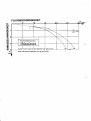 2
2
-
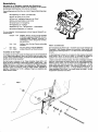 3
3
-
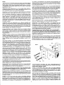 4
4
-
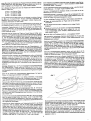 5
5
-
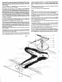 6
6
-
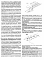 7
7
-
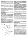 8
8
-
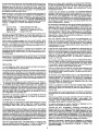 9
9
-
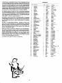 10
10
-
 11
11
-
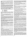 12
12
-
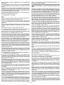 13
13
-
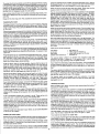 14
14
-
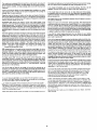 15
15
-
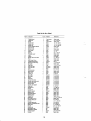 16
16
-
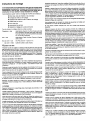 17
17
-
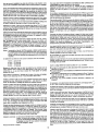 18
18
-
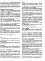 19
19
-
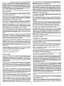 20
20
-
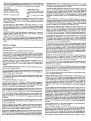 21
21
-
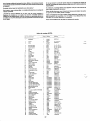 22
22


MULTIPLEX Alpina Le manuel du propriétaire
- Catégorie
- Jouets télécommandés
- Taper
- Le manuel du propriétaire
dans d''autres langues
- English: MULTIPLEX Alpina Owner's manual
- Deutsch: MULTIPLEX Alpina Bedienungsanleitung
Documents connexes
-
MULTIPLEX Dg 300 Le manuel du propriétaire
-
-
-
-
-
-
-
-
-