
DAVIT CRANES
Instructions & Operation Manual
TO PREVENT SERIOUS INJURY, READ AND UNDERSTAND
ALL WARNINGS AND INSTRUCTIONS BEFORE USE.
Due to continuing improvements,actual product may differ slightly from the product described herein.
ISO 9001:2008
ISO/TS 16949 2009

- 01 -
Description
Unpacking
Instructions for Installing the Crane
Safe Warnings and Precautions
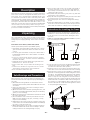
Davit cranes are perfect for permanent or portable installation.
These cranes consist of an angled beam which pivots over a
vertical axis. They can have fixed or adjustable booms, and
are available in portable as well as stationary units. Davit
cranes incorporate a hand operated and cable assembly for
load handling. Independent bases (Optional-Sold Separately)
allow you to move the davit crane from base to base, so one
davit crane can serve more than one lift station. Standard davit
cranes feature an electrostatic powder coating to resist
corrosion. Galvanized and stainless steel models provide added
protection in harsh environments.
Davit Cranes Series 500 lb, 1,000 lb and 2,000 lb
Hand or power winch operation up to 2000 lb capacity
UÊ>`ÊÜV operated models include spur gear or worm
gear hand winch with automatic disc brake for load
control.
UÊ/iÊÜÀÊ}i>ÀÊ>`ÊÜVÊV>ÊLiÊ«ÜiÀÊ`riven with a
maximum 400 rpm drill-motor. Not available for 500 LB
series cranes.
UÊorrosion resistant finish with electrostatic powder
coating and corrosion resistant fasteners. Galvanized
finish also available,
UÊ`ÕÃÌ>LiÊLÃÊ«ÀÛ`iÊ`vviÀiÌÊi}ÌÊ>`ÊÀi>V
combinations for various size loads.
UÊÀ>iÊÀÌ>ÌiÃÊÎÈäcÊÊ>Ê«Ê>`ÊÃiiÛiÊLi>À}ÊÊÌiÊ
base.
UÊ-Ì>iÃÃÊÃÌiiÊ`iÃÊvÀÊ}ÊÃiÀÛViÊviÊÊVÀÀÃÛiÊ
environments, with stainless steel hand winch.
UÊ>ÃiÃÊÊ*i`iÃÌ>Ê>`Ê-ViÌÊÃÌÞi°
vÌiÀÊÕ«>V}ÊÌiÊVÀ>i]Ê inspect carefully for any damage
Ì>ÌÊ>ÞÊ>ÛiÊVVÕÀÀi`Ê`ÕÀ}ÊÌÀ>ÃÌ°ÊiVÊvÀÊÃÃ}ÊÀÊ
damaged parts. Shipping damage claims must be filed with
carrier.
When using this crane, safety precautions should always be
followed to reduce the risk of personal injury and damage to
the crane.
1) Read and follow the guidelines set forth in this owner’s
manual. Keep the manual, and all decals adhered to the crane
at all times.
2) Inspect all components of the crane according to owner’s
manual before operation.
ήÊ"«iÀ>ÌÀÃÊÕÃÌÊLiÊÜiÊÌÀ>i`ÊÊ«iÀ>Ì}ÊÌÃÊVÀ>i]Ê>`Ê
should be properly dressed (hard hat, safety shoes and safety
glasses, no loose clothing).
4) Operators must know the load and the load must not exceed
the crane rated capacity.
5) The load must be clear of other objects and free to move.
Make sure the load will not tip, spin, roll away, or in any
way move uncontrollably.
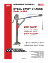
È®Ê`ÕÃÌÊÌiÊLÊÌÊ«À«iÀÊ«ÃÌÊÃÊÌ>ÌÊÌiÊ>`ÊÊÃÊ
centered over the load°ÊÛ`ÊÃ`iÊ«ÕÃÊÜVÊVuld damage
the crane or cause the load to tip.
7) When adjusting the boom, set the boom angle a bit above
horizontal and hold the boom extension firmly to avoid it
sliding out of the boom causing damage or injury.
8) Keep at least 5 wraps of wire rope wound on the drum of
the winch at all times, to serve as anchor wraps. With less
than 5 wraps on the drum the wire rope could come loose,
causing the load to fall off.
9) Keep hands away from sheaves, gears, wire rope, and other
moving parts of the equipment.
10) Keep all unnecessary personnel away from the crane while
in operation. Keep out of the path of the load.
11) Do not lift people. The crane is not designed for lifting
people.
£Ó®Ê-Ì>ÞÊiÀÌ\Ê7>ÌVÊÜ>ÌÊÞÕÊ>ÀiÊ`}°Ê1ÃiÊÞÕÀÊVÊ
sense. Do not use this crane when you are tired, stressed or
when under the influence of drugs, alcohol or medication.
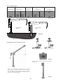
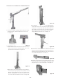
Figure 1
center line
correct
center line
incorrect
UÊʵÕ>vi`Ê«ÀviÃÃ>ÊÃÕ`ÊëiVÌÊÀÊ`iÃ}ÊÌi
foundation to insure that it will provide adequate support.
UÊLocate the crane so it will be visible during the entire
operation.
£®Ê" -1/Ê**Ê"-Ê Ê,1/" - for specific
rules on installing the equipment.
2) Locate the crane in an area clear of traffic and obstacles that
could interfere with operation. Make sure the crane is
accessible for maintenance and operation.
ήÊÃÌ>ÊÌiÊVÀ>iÊÊ>ÊiÛiÊÃÕÀv>Vi°ÊÊÕiÛiÊÃÕÀv>ViÊ>ÞÊ
cause the boom to rotate in the direction the mast is leaning.
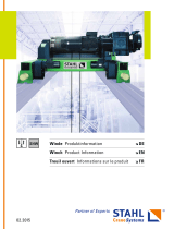
4) Fasten the base securely to the foundation to withstand
applicable overturning moments and mounting bolt reaction.
See Table 1. For standard products referred to in this manual,
ÊÊÊÊÕÃiÊÎÉnÊVÊÀÊxÉnÊVÊV>ÀÃiÊÌÀi>`Êv>ÃÌiiÀÃ]ÊÊ}À>`iÊxÊÀÊ
biÌÌiÀ°Ê/ÀµÕiÊvÀÊÊÎÉnÊVÊ}À>`iÊÊxÊv>ÃÌiiÀÃÊÜÌÕÌÊ
lubric>ÌÊÃÊÎäÊvÌÊLÃÊ]Ê/ÀµÕiÊvÀÊxÉnÊVÊ}À>`iÊxÊv>ÃÌiiÀÃÊ
without lubrication is 150 ft lbs. Make sure mounting holes
are secured to a solid foundation able to support the crane
and the load under all conditions with design factors based
on accepted engineering practices.
Base installed
upright
Base installed
flush
Figure 2A

- 02 -
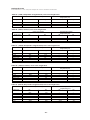
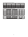
Table 1 – Crane Reactions
Crane model
500 lbs
1000 lbs
2000 lbs
Mast moment Suggested
Bolt size
M10
M16
M16
Axial force
Pedestal Base only
in-lb
21,000
36,000
91,200
N.m
2,373
4,068
10,306
Lb
2,121 lbs
1,756 lbs
4,447 lbs
N
9,435
7,811
19,781
Torque for grade
8.8 fasteners
without lubrication
N.m
40
200
200
Base installed
upright
Base installed
flush
Figure 2B
Force in tension
Crane at 45°
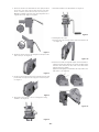
2. Put the mast into the base. This mast can rotate 360°.
See Figure 4.
Figure 4
Assembling the Crane For 500 Lb series cranes
Figure 3
1. There are two different types of bases. One style is a pedestal
and the other is a socket base. (Both of these are optional
accessories)Before installing the base, fix the roller to the
bottom of the base. After the base is installed, insert the
nylon sleeve as shown in Figure 3.
roller roller
500 lb series pedestal base 500 lb series socket base

- 03 -
Figure 6
Figure 9
Figure 10
Figure 11
Figure 8
Figure 7
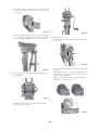
4. Attach the sheave to the boom using the cleavis pin. Secure
with cotter pin. See Figure 6.
5. At the very front sides of the boom, install the stop pin and
put the hair cotter pin into the stop pin to secure it in place.
See Figure 7.
6. Attach the hand winch to the mounting plate using
hardware. See Figure 8.
7. Attach the handle to the hand winch. See Figure 9.
cotter
pin
into
the
stop
pin
3. Fasten the boom to the mast with the clevis pins provided.
Secure the clevis pins in place with the hair cotter pins.
Please view the picture below. There are two places
marked as A and B on the left clevis pin. They function to
regulate the crane angle. See Figure 5.
marked
as
A
and
B
on
the
left
clevis
pin
.
They
fu
e
gu
l
ate t
h
e crane ang
l
e. See Figure 5.
A
B
Figure 5
8. Installing the wire rope:
1) Pass the wire rope over the sheave at the end of the boom.
See Figure 10.
2) Insert the steel cable through the square hole from inside to
outside. Insert the steel cable into one side of the cable anchor.
Insert the cable end into the other side of the cable anchor
leaving a large loop outside.
Tighten the nut slightly. Pull and reduce the loop down to the
cable anchor . (See Figure.11)

- 04 -
Figure 17
pedestal base socket base
Figure 12
Figure 14
Figure 15
Figure 16
Figure 13
Instructions for Assembling the 1,000lb/2,000lb Crane
1. There are two kinds of base pedestal and socket. After
installing the base, install the nylon sleeve on its top.
See Figure 12.
2. Assembling the crane:
1) Install the mast in the base. Move the mast side to side to
make sure the bottom of the mast properly seats on the
pin in the bottom of the base. See Figure 13.
2) Fasten the boom to the mast with the clevis pin which is
secured in place by the lynch pin. The lynch pin is fixed
with the carrying handle by the wire rope. Pay attention
that the carrying handle on the boom should be located
on the same side as the handle on the mast. See Figure 14.
3) First adjust the ratchet jack to the greatest length and then
install it when the boom is at horizontal position. Apply the
clevis pins to secure the two ends of the ratchet jack to the
mast and boom respectively. The clevis pins are fastened
tight by the lynch pins. The lynch pins are fixed with
carrying handles by the wire rope. See Figure 15.
4) Slide the boom extension into the boom and secure in place
with the clevis pin and lynch pin provided. The lynch pin is
fixed with the carrying handle by the wire rope. Please see
the assembly drawing below. See Figure 16.
5) Attach the sheave with the clevis pin while using the cotter
pin to prevent the clevis pin from falling off. Bend the cotter
pin properly so as to secure itself in place. See Figure 17.

- 05 -
Figure 23
Figure 20
Figure 19
Figure 21
Figure 22
7) Install the handle on the lower end of the boom, applying
the clevis pin and lynch pin provided. The lynch pin is fixed
with the carrying handle by the wire rope. See Figure 19.
8) Secure the hand winch to the mounting plate (Figure 20)
using hardware.
9) Install the handle onto the hand winch and tighten the
fastening screw. See Figure 21.
10) Installing the wire rope:
ÊÊÊÊUÊ*ass the wire rope over the sheave at the end of the boom.
See Figure 22.
UÊÊÃiÀÌÊÊÌiÊÃÌiiÊV>LiÊÌÀÕ}ÊÌiÊõÕ>ÀiÊÊiÊÊvÀÊÊÃ`iÊÊ
to outside.
Thrust the steel cable into one side of the cable anchor .
Insert the cable end into the other side of the cable anchor
leaving a large loop outside.
/}ÌiÊÊÌiÊÊÕÌÊÊÃ}ÌÞ°Ê*ÕÊ>`ÊÀi`ÕViÊÊÌiÊ«Ê`ÜÊÌ
the cable anchor . (See Figure.23)
Figure 18
6) At the very front sides of the boom, install the stop pin and
put the hair cotter pin into the stop pin to secure it in place.
See Figure 18.

- 06 -
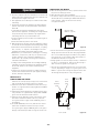
filler/
breather
plug
lever
check
plug
drain
plug
floor mount Figure 25
ÊÊUÊÕLÀV>Ìe the outboard bearing at least once every month
or more, depending on usage. Use a grease gun to insert
ÊÊÊÊÊ Ê°ÊÓÊ}Ài>ÃiÊÕÌÊVi>Ê}Ài>ÃiÊ>««i>ÀÃÊ>ÌÊÌiÊÃi>ð
ÊÊÊÊÊ/iÊLi>À}ÊÜÊõÕi>ÊvÊÌÊÃÊ`ÀÞ°Ê-iiÊ}ÕÀiÊÓ{°
{°ÊÕÌÞÊÀ>Ì}Ã refer to the type of use the equipment is subject
to. Consider the following when determining duty rating.
ÊUÊEnvironment: harsh environments include hot, cold, dirty,
wet, corrosive, or explosive surroundings. Protect the
equipment from harsh environments when possible.
ÊUÊMaintenance: poor maintenance, meaning poor cleaning,
lubrication, or inspection, leads to poor operation and
possible damage of the equipment. Minimize poor
maintenance by carefully following the instructions
contained in this manual.
ÊUÊ>`}\ÊÃiÛiÀiÊ>`}ÊVÕ`iÃÊÃVÊ>`}Ê>`ÊvÌ}
loads that exceed the load rating of the equipment. Avoid
shock loads, and do not exceed the load rating of the
equipment.
ÊUÊFrequency of operation: frequent or lengthy operations
increase wear and shorten the life span of gears, bearings,
sheaves, and other components.
ÊÊÊÊÕLÀV>ÌiÊÌiÊVÀ>iÊ«À«iÀÞÊÌÊi«Ê«ÀÌiVÌÊÌÊvÀÊÜi>ÀÊ
and rust. Read the following instructions carefully.
£®ÊÕLÀV>ÌiÊ>Ê«ÃÊLivÀiÊÃÌ>>ÌÊ>`Ê>ÌÊi>ÃÌÊiÛiÀÞÊÎÊ
mÌðÊ1ÃiÊ>Ê}Ài>ÃiÊLÀÕÃÊÌÊ>««ÞÊ>Ê}ÌÊvÊvÊ ÊÓ
grease to all pins.
Ó®Êubricate the mast bearing before installation and at least
everÞÊÎÊÌðÊ1ÃiÊ>Ê}Ài>ÃiÊLÀÕÃÊÌÊ>««ÞÊ>ÊvÊvÊ ÓÊ
grease to both inside and outside surfaces.
ήÊÕLÀV>ÌiÊÌiÊ«ÊLÕÃ}ÊV>Ìi`ÊÊÌiÊLÌÌÊvÊÌiÊ
ÊÊÊÊ>ÃÌÊLivÀiÊÃÌ>>ÌÊ>`Ê>ÌÊi>ÃÌÊiÛiÀÞÊÎÊÌð
ÊÊÊÊ1ÃiÊ>Ê}Ài>ÃiÊLÀÕÃÊÌÊ>««ÞÊ>ÊvÊvÊ ÊÓÊ}Ài>ÃiÊÌÊ
the bushing.
{®ÊÀÊ£äääÊLÉÓäääÊL®ÊÃiÀiÃÊVÀ>i]ÊÕLÀV>ÌiÊÌiÊÀ>ÌViÌÊ
ÊÊÊÊ>VÊLivÀiÊÃÌ>>ÌÊ>`Ê>ÌÊi>ÃÌÊiÛiÀÞÊÎÊÌðÊ
UÃiÊ>Ê}Ài>ÃiÊ}ÕÊÌÊ>««ÞÊ>Ê ÊÓÊ}Ài>ÃiÊÌÊÌiÊ}Ài>Ãi
fittings on the ratchet jack until excess grease can be seen.
LUBRICATING THE WINCH
£®ÊÕLÀV>ÌiÊÜVÊ}i>ÀÃÊLivÀiÊiÛiÀÞÊ«iÀ>ÌÊ>`Ê>ÌÊi>ÃÌÊ
ÊÊÊÊiÛiÀÞÊ£äÊÕÀÃÊ`ÕÀ}Ê«iÀ>Ì°
Ó®ÊÕLÀV>Ì}ÊÌiÊÜÀÊ}i>ÀÊ>`Ê7V
ÊÊUÊ/he winch is shipped from the factory with the proper
ÊÊÊÊÊ>ÕÌÊ{{ÊÕViîÊvÊLÊ}i>ÀÊÈääÊ8*ÊÓÓäÊÕLÀV>ÌÊ
iÊÌiÊ}i>ÀLÝ°ÊÊÕLÀV>ÌiÊÌiÊÜVÊ>ÃÊvÜÃ]Ê
ÊÊÊÊÊÃiiÊ}ÕÀiÃÊÓ{Ê>`ÊÓx°
lubricate with
Ê°ÊÓÊ}Ài>Ãi
Figure 24
ÊÊUÊiVÊÊiÛiÊLivÀiÊiÛiÀÞÊ«iÀ>ÌÊ>`ÊiÛiÀÞÊ£äÊÕÀÃÊ
during operation. Remove the level check plug and make
sure oil is even with the plug hole. Add oil to the gearbox
ÊÊÊÊÊvÊiViÃÃ>ÀÞ°ÊÊÌÊÕÃiÊÃÞÌiÌVÊÕLÀV>ÌÃÊ>`Ê`ÊÌÊ
ÊÊÊÊÊÝÊ`vviÀiÌÊÕLÀV>ÌðÊ-iiÊ}ÕÀiÊÓx°
ÊÊUÊ>}iÊ}i>ÀLÝÊÊ>ÌÊi>ÃÌÊiÛiÀÞÊÈÊÌÃ]ÊÀÊÜiiÛiÀÊ
it is dirty or contaminated. Remove the drain plug to
ÊÊÊÊÊ`À>ÊÊvÀÊÌiÊ}i>ÀLÝ°Ê-iiÊ}ÕÀiÊÓx°Ê
Maintenance:
LUBRICATING THE CRANE
1. The force required to lift the load must not exceed the load
rating of the crane. Consider the total force required to lift
the load, not the weight of the load.
Ó°Ê/ÃÊiµÕ«iÌÊV>ÊÌÊ`iÛi«ÊvÀViÃÊÌ>ÌÊÜÊiÝVii`ÊÌi
load rating.
ΰÊ*iÀvÀ>ViÊÀ>Ì}ÃÊvÊÌiÊiµÕ«iÌÊ>ÀiÊ>vviVÌi`ÊLÞÊÌiÊ
position of the boom. See the performance characteristics
ÊÊÊÊ/>LiÃÊÇ°Ê
ÊUÊ>`ÊÀ>Ì}ÊÀi«ÀiÃiÌÃÊÌiÊ>ÝÕÊvÀViÊÌ>ÌÊV>ÊLi
ÊÊÊÊ«>Vi`ÊÊiÜÊÊiµÕ«iÌ°Ê>`ÊÀ>Ì}ÃÊ>ÀiÊ>ÃÃ}i`ÊÛ>ÕiÃÊ
for specific boom positions and wire rope lengths. Crane
load ratings decrease as you extend the boom.
ÊUÊvÌÊÛ>ÀiÃÊÜÌÊÌiÊ«ÃÌÊvÊÌiÊLÊÊ>`ÊÌiÊi}ÌÊvÊ
the wire rope.
ÊUÊ,i>VÊÛ>ÀiÃÊÜÌÊÌiÊ«ÃÌÊvÊÌiÊL°ÊÊ
Operation

- 07 -
Table 2C - (1000 lb, Red powder coat/galvanized) series crane weight chart
Component
Mast
Boom
Boom extension
Ratchet jack
Handle
Total
Component weight
LB Kg
56.4
38.6
22.5
12.3
5.5
135.3
Assembly/disassembly
weight(with pins)
LB Kg
—
—
—
—
—
138
25.6
17.5
10.2
5.6
2.5
61.4
—
—
—
—
—
62.6
Component
Mast
Boom
Boom extension
Ratchet jack
Handle
Total
Component
Mast
Boom
Boom extension
Ratchet jack
Handle
Total
Component weight
LB Kg
55.1
40.8
27.1
12.3
6.6
141.9
Assembly/disassembly
weight(with pins)
LB Kg
—
—
—
—
—
144.6
25
18.5
12.3
5.6
3
64.4
—
—
—
—
—
65.6
Table 2D - (1000 lb, stainless) series crane weight chart
Storing the crane
Store the crane in a cool clean place away from corrosive chemicals and moisture.
Table 2A - (500lb , Red powder coat/galvanized ) series crane weight chart
Table 2B - (500 lb, stainless) series crane weight chart
Component
Mast
Boom
Total
Component weight
LB
30.9
34.4
65.3
Assembly/disassembly
weight(with pins)
LB Kg
— —
— —
67 30.4
Kg
14
15.6
29.6
Component
Mast
Boom
Total
Component weight
LB
28.7
30.4
59.1
Assembly/disassembly
weight(with pins)
LB Kg
— —
— —
61 27.6
Kg
13
13.8
26.8
Table 2E - (2000 lb, Red powder coat/galvanized) series crane weight chart
Component weight
LB Kg
69.4
67.2
54.1
12.3
5.5
208.5
Assembly/disassembly
weight(with pins)
LB Kg
—
—
—
—
—
214.5
31.5
30.5
24.5
5.6
2.5
94.6
—
—
—
—
—
97.3

- 08 -
Table 3A - Spur gear hand winch performance characteristics
Table 3B - Worm Gear Hand Winch performance characteristics
Description
1000 lb-marine
duty with brake
1000 lb-stainless
steel with brake
2500 lb-marine
duty with brake
2500 lb-stainless
steel with brake
3500 lb-marine
duty with brake
Load rating(lb)
1st
layer Mid
drum
Full
drum
1st
layer Mid
drum
Full
drum
1000
1000
2500
2500
3500
700
700
2000
2000
2700
500
500
1600
1600
2000
Wire
rope
dia. (in)
Force
to lift
1000 lb
Approx.
Ship
Wt. (lb)
3/16
3/16
1/4
1/4
1/4
Drum capacity (ft)2
3.8
6
4.8
4.8
6
19.4
39
17
17
30
50.4
86
52
52
91
3.1:1
3.83:1
11:1
11:1
18.4:1
36 lb
20 lb
18 lb
18 lb
13 lb
7
15.4
15
15
19.4
Gear
ratio
Description
2000 lb
Load rating(lb)
1st
layer Mid
drum
Full
drum
1st
layer Mid
drum
Full
drum
2000
2000
1500
1500
1200
1200
Wire
rope
dia. (in)
Force
to lift
1000 lb
Approx.
Ship
Wt. (lb)
1/4
5/16
Drum capacity (ft)2
11
8
35
25
77
52 32:1 14 lb
14 lb 36.65
Gear
ratio
Component
Mast
Boom
Boom extension
Ratchet jack
Handle
Total
Component weight
LB Kg
77.4
90.4
59.1
12.3
6.6
245.8
Assembly/disassembly
weight(with pins)
LB Kg
—
—
—
—
—
251.8
35.1
41
26.8
5.6
3
111.5
—
—
—
—
—
114.2
Table 2F - (2000 lb, stainless) series crane weight chart

- 09 -
500 lb crane series 1000 lb/2000 lb crane series
lift below
floor level
1234
Figure 26
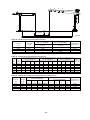
Table 4B - 1000 lbs Series Performance Characteristics
wire
rope
dia.
1/4 in
1/4 in
1/4 in
1/4 in
1/4 in
1/4 in
wire
rope
length
36 ft
60 ft
36 ft
60 ft
36 ft
60 ft
Position
1
—
—
1000 lbs
1000 lbs
—
—
Position
2
—
—
700 lbs
700 lbs
—
—
Position
4
—
—
500 lbs
500 lbs
—
—
Position
3
—
—
600 lbs
600 lbs
—
—
Position
1
1000 lb
1000 lb
—
—
—
—
Position
2
700 lbs
700 lbs
—
—
—
—
Position
4
500 lbs
500 lbs
—
—
—
—
Position
3
600 lbs
600 lbs
—
—
—
—
Position
1
—
—
—
—
1000 lbs
1000 lbs
Position
2
—
—
—
—
700 lbs
700 lbs
Position
4
—
—
—
—
500 lbs
500 lbs
Position
3
—
—
—
—
600 lbs
600 lbs
17-21 ft
41-45 ft
17-21 ft
41-45 ft
17-21 ft
41-45 ft
Lift below
floor level
(min-max)
Load rating for 1000 lbs crane series
with winch RBW2500SS
Load rating for 1000 lbs crane series
with winch ROW2000
Load rating for 1000 lbs crane series
with winch RBW2500
Table 4A - 500 lbs Series Performance Characteristics
wire rope
dia.
3/16 in
3/16 in
3/16 in
3/16 in
500 lbs crane Series
with winch RBW1000
500 lbs crane Series
with winch RBW1000SS
wire rope
length
20 ft
45 ft
20 ft
45 ft
Load rating
Position
500 lb
500 lb
—
—
Load rating
Position
—
—
500 lb
500 lb
Lift below floor
level(min-max)
9-10 ft
34-35 ft
9-10 ft
34-35 ft
Table 4C - 2000 lbs Series single-part ling Performance Characteristics
wire rope
dia.
1/4 in
1/4 in
1/4 in
1/4 in
wire rope
length
36 ft
60 ft
36 ft
60 ft
Position
1
2000 lb
2000 lb
—
—
Position
2
1600 lbs
1600 lbs
—
—
Position
4
1000 lbs
1000 lbs
—
—
Position
3
1300 lbs
1300 lbs
—
—
Position
1
—
—
2000 lbs
2000 lbs
Position
2
—
—
1600 lbs
1600 lbs
Position
4
—
—
1000 lbs
1000 lbs
Position
3
—
—
1300 lbs
1300 lbs
16-20 ft
40-44 ft
16-20 ft
40-44 ft
Lift below floor
level(min-max)
Load rating for 2000 lbs crane series
with winch ROW2000
Load rating for 2000 lbs crane series
with winch RBW3500

13
14
15
16
17-1
11
10
9
8
7
19
66
5-1 5-2
4
4
3
3
2
2
11
12
- 10 -
18-1
17-2
18-2
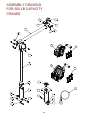
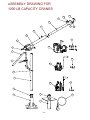
A
SSEMBLY DRAWING
FOR 500 LB CAPACITY
CRANES

- 11 -
1
2
3
4
5-1
5-2
6
7
8
9
10
11
12
13
14
15
16
17-1
18-1
17-2
18-2
19
2
1
1
1
1
1
1
1
2
2
1
1
1
1
1
1
1
1
3
1
3
1
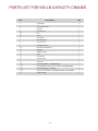
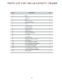
Item Description Qty
Copper Bush
Spring Washer M12
Nut M12
Bolt M12×110
Base
Socket
Fixed Sleeve
Mast Weldment
“R” Cotter Pin
12×100B Safety Pin
Movable Arm Weldment
Safety Pin
6×50B Safety Pin
Pully
Copper Bush
“R” Cotter Pin
Cotter Pin
Winch RBW1000 (For RC500P/RC500Z)
Bolt M10×30+Flat washer 10+ Nut M10 (For RC500P/RC500Z)
Winch RBW1000SS (For RC500S)
Stainless Bolt M10+Flat washer Ø10+ Nut M10×3 (For RC500S)
Cable Assembly
PARTS LIST FOR 500 LB CAPACITY CRANES

- 12 -
1-1
1-2
2
2
3
4
5
6
7
8
9
10
11
12
13
14
15 16
17
18-1
19-1
19-2
19-3
20
18-2
18-3
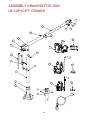
A
SSEMBLY DRAWING FOR
1000 LB CAPACITY CRANES

1-1
1-2
2
3
4
5
6
7
8
9
10
11
12
13
14
15
16
17
18-1
19-1
18-2
19-2
18-3
19-3
20
1
1
1
1
2
1
1
5
1
1
1
1
1
1
1
1
1
1
1
3
1
3
1
3
1
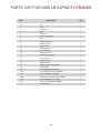
Base
Socket
Fixed Sleeve
Mast
Ø16×75 Safety Pin
Ratchet Jack Assembly
Lever
Lockpin Assembly
Ø16×75 Safety Pin
Ø19×125 Safety Pin
Upper Bracket
Ø12.5×100 Safety Pin
Telescopic Bar Weldment
4×28 Lockpin
“R” Safety Pin
Ø19×55 Safety Pin
6×50B Pin with holes in the head
Pully Assembly
Winch ROW2000 (For RC1000P)
Bolt M10×34+Nut M10 (For RC1000P)
Winch RBW2500 (For RC1000Z)
Bolt M10×18 (For RC1000Z)
Winch RBW2500SS (For RC1000S)
Stainless Bolt M10×18 (For RC1000S)
Cable Assembly
- 13 -
Item Description Qty
PARTS LIST FOR 1000 LB CAPACITY CRANES

1-1
2
1-2
2
3
4
10
5
6
7
8
9
11
13 16
17
18
15
14
12
- 14 -
19-1
20-1
20-3
19-3
19-3 20-2
21
A
SSEMBLY DRAWING FOR 2000
LB CAPACITY CRANES

- 15 -
Item Description Qty
1-1
1-2
2
3
4
5
6
7
8
9
10
11
12
13
14
15
16
17
18
19-1
20-1
19-2
20-2
19-3
20-3
21
1
1
1
1
1
1
1
1
2
1
1
5
1
1
1
1
1
1
1
1
3
1
3
1
3
1
Base
Socket
Fixed Sleeve
Mast
Safety Pin
Ratchet Jack Assembly
Lever
Ø16X75 Safety Pin
Ø27X85 Safety Pin
Upper Bracket
Ø32X154 Safety Pin
Lockpin Assembly
Ø23X135 Safety Pin
Telescopic Bar Weldment
3.2X28 Cotter Pin
1.2X12 Cotter Pin
Ø19X55Safety Pin
6X50B Pin with holes in the head
Pully Assembly
Winch ROW2000 (For RC2000P)
Bolt M10×34+Nut M10 (For RC2000P)
Winch RBW3500 (For RC2000Z)
Bolt M12×18+Bolt M12×25 (For RC2000Z)
Winch RBW2500SS (For RC2000S)
Stainless Bolt M10×18 (For RC2000S)
Cable Assembly
PARTS LIST FOR 2000 LB CAPACITY CRANES
-
 1
1
-
 2
2
-
 3
3
-
 4
4
-
 5
5
-
 6
6
-
 7
7
-
 8
8
-
 9
9
-
 10
10
-
 11
11
-
 12
12
-
 13
13
-
 14
14
-
 15
15
-
 16
16


Endurance Marine Davit / Deck Crane Le manuel du propriétaire
- Taper
- Le manuel du propriétaire
- Ce manuel convient également à
dans d''autres langues
Autres documents
-
 OZ LIFTING PRODUCTS OZSOC3 Le manuel du propriétaire
-
Sunex Tools 5222 Le manuel du propriétaire
-
Danby 3824-527 Le manuel du propriétaire
-
Wacker Neuson TH522 (TL48-01) Manuel utilisateur
-
 probst AKZ-UNI-H Manuel utilisateur
-
Hobie FX One Assembly Manual
-
GYS MULTI TOOL TRUCK Le manuel du propriétaire
-
 STAHL CraneSystems Winch Le manuel du propriétaire
-
-
Greenlee G6 Turbo Tugger Cable Puller Manuel utilisateur


