MULTIPLEX Rr Funcub Ng Le manuel du propriétaire
- Taper
- Le manuel du propriétaire

© Copyright by MULTIPLEX Modellsport GmbH & Co. KG 2019
Erhältliche Varianten | Available versions
Version disponible | Varianti disponibili
Variantes disponibles
FunCub NG # 1-01526
blau | blue | bleu | blu | azul
FunCub NG # 1-01333
grün | green | vert | verde
FR
IT
ES
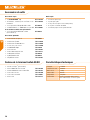
Sicherheitshinweise 2 - 3
Zubehör und Werkzeug, Lieferumfang 4 - 5
Bauanleitung 6 - 7
Ersatzteile 8 - 9
Abbildungen 26 - 27
Conseils de sécurité 18 - 19
Accessoires et outils, contenu 20 - 21
Notice de montage 22 - 23
Pièces de rechanges 24 - 25
Illustrations 26 - 27
Instrucciones de seguridad 36 - 37
Accesorios y herramientas, suministro 38 - 39
Instrucciones de montaje 40 - 41
Repuestos 42 - 43
Ilustraciónes 26 - 27
Safety information 10 - 11
Accessories and tools, contents 12 - 13
Assembly instructions 14 - 15
Spare parts 16 - 17
Illustrations 26 - 27
Istruzioni di sicurezza 28 - 29
Accessori e utensili, ambito fornitura 30 - 31
Istruzioni di montaggio 32 - 33
Parti di ricambio 34 - 35
Illustrazioni 26 - 27
DE EN

2
Sicherheitshinweise für MULTIPLEX-Flugmodelle
Beim Betrieb des Modells sind alle Warn- und Sicherheitshin-
weise der Betriebsanleitung unbedingt zu beachten.
Das Modell ist KEIN SPIELZEUG im üblichen Sinne. Benutzen Sie Ihr
Modell mit Verstand und Vorsicht, und es wird Ihnen und Ihren Zuschauern
viel Spaß bereiten, ohne eine Gefahr darzustellen. Wenn Sie Ihr Modell
nicht verantwortungsbewusst betreiben, kann dies zu erheblichen
Sachbeschädigungen und schwerwiegenden Verletzungen führen. Sie
alleine sind dafür verantwortlich, dass die Betriebsanleitung befolgt und
die Sicherheitshinweise in die Tat umgesetzt werden.
Mit Inbetriebnahme des Modells erklärt der Betreiber, dass er den Inhalt der
Betriebsanleitung, besonders zu Sicherheitshinweisen, Wartungsarbeiten,
Betriebsbeschränkungen und Mängeln kennt und verstanden hat.
Dieses Modell darf nicht von Kindern unter 14 Jahren betrieben
werden. Betreiben Minderjährige das Modell unter der Aufsicht eines
fürsorgepichtigen und sachkundigen Erwachsenen im Sinne des
Gesetzes, ist dieser für die Umsetzung der Hinweise der Betriebsanleitung
verantwortlich.
DAS MODELL UND DAZUGEHÖRIGES ZUBEHÖR MUSS VON KINDERN
UNTER 3 JAHREN FERNGEHALTEN WERDEN! ABNEHMBARE KLEINTEILE
DES MODELLS KÖNNEN VON KINDERN UNTER 3 JAHREN VERSCHLUCKT
WERDEN. ERSTICKUNGSGEFAHR!
Die Multiplex Modellsport GmbH & Co. KG ist nicht haftungspichtig für
Verluste, Beschädigungen und Folgeschäden jeder Art, die aufgrund
falschen Betriebs, nicht bestimmungsgemäßer Verwendung oder
Missbrauchs dieses Produkts, einschließlich der damit verwendeten
Zubehörteile entstehen.
Bestimmungsgemäße Verwendung
Das Modell darf ausschließlich im Hobbybereich verwendet werden. Jede
andere Art der Verwendung ist nicht erlaubt. Zum Betrieb des Modells
darf nur das von Multiplex empfohlene Zubehör verwendet werden. Die
empfohlenen Komponenten sind erprobt und auf eine sichere Funktion
passend zum Modell abgestimmt. Werden andere Komponenten
verwendet oder das Modell verändert, erlöschen sämtliche etwaigen
Ansprüche gegenüber Hersteller bzw. Vertreiber.
Um das Risiko beim Betrieb des Modells zu minimieren, beachten Sie
insb. folgende Punkte:
• Das Modell wird über eine Funkfernsteuerung gelenkt. Keine
Funkfernsteuerung ist sicher vor Funkstörungen. Störungen können
zum Kontrollverlust über das Modell führen. Achten Sie deshalb beim
Betrieb des Modells jederzeit und unbedingt auf große Sicherheits-
räume in alle Richtungen. Schon beim kleinsten Anzeichen von
Funkstörungen ist der Betrieb des Modells sofort einzustellen!
• Das Modell darf erst in Betrieb genommen werden, nachdem ein
kompletter Funktions- und Reichweitentest gemäß der Anleitung der
Fernsteuerung erfolgreich ausgeführt wurde.
• Das Modell darf nur bei guten Sichtverhältnissen geogen werden.
Fliegen Sie nicht bei schwierigen Lichtverhältnissen und nicht in
Richtung der Sonne, um Blendungen zu vermeiden.
• Das Modell darf nicht unter Einuss von Alkohol und anderen
Rauschmitteln betrieben werden. Gleiches gilt für Medikamente, die
das Wahrnehmungs- und Reaktionsvermögen beeinträchtigen.
• Fliegen Sie nur bei Wind- und Wetterverhältnissen, bei denen Sie
das Modell sicher beherrschen können. Berücksichtigen Sie auch bei
schwachem Wind, dass sich Wirbel an Objekten bilden und auf das
Modell Einuss nehmen können.
• Fliegen Sie nie an Orten, an denen Sie andere oder sich selbst
gefährden, z.B. in Wohngebieten, an Überlandleitungen, Straßen und
Bahngleisen.
• Niemals auf Personen und Tiere zuiegen! Vermeiden Sie unnötige
Risiken und weisen Sie auch andere Piloten auf mögliche Gefahren
hin. Fliegen Sie immer so, dass weder Sie noch andere in Gefahr
kommen – auch langjährige, unfallfreie Flugpraxis ist keine Garantie
für die nächste Flugminute.
Restrisiken
Auch wenn das Modell vorschriftsmäßig und unter Beachtung aller
Sicherheitsaspekte betrieben wird, besteht immer ein Restrisiko.
Eine Haftpichtversicherung (Modellugzeug mit Antrieb) ist daher
obligatorisch. Falls Sie Mitglied in einem Verein oder Verband sind,
können Sie ggf. dort eine entsprechende Versicherung abschließen.
Achten Sie jederzeit auf die Wartung und den ordnungsgemäßen Zustand
von Modellen und Fernsteuerung.
Aufgrund der Bauweise und Ausführung des Modells können insb.
folgende Gefahren auftreten:
Verletzungen durch die Luftschraube: Sobald der Akku angeschlossen
ist, ist der Bereich um die Luftschraube freizuhalten. Beachten Sie, dass
Gegenstände vor der Luftschraube angesaugt oder dahinter weggeblasen
werden können. Richten Sie das Modell immer so aus, dass es sich im
Falle eines ungewollten Anlaufens des Motors nicht in Richtung anderer
Personen bewegen kann. Bei Einstellarbeiten, bei denen der Motor läuft
oder anlaufen kann, muss das Modell stets von einem Helfer sicher
festgehalten werden.
• Absturz durch Steuerfehler: Auch dem erfahrensten Piloten können
Fehler unterlaufen. Fliegen Sie daher stets nur in sicherer Umgebung
und auf zugelassenen Modelluggeländen.
• Absturz durch technisches Versagen oder unentdeckten Transport-
oder Vorschaden: Das Modell ist vor jedem Flug unbedingt sorgfältig
zu überprüfen. Rechnen Sie jederzeit damit, dass es zu technischem
oder Materialversagen kommen kann. Betreiben Sie das Modell
daher stets nur in sicherer Umgebung.
• Betriebsgrenzen einhalten: Übermäßig hartes Fliegen schwächt die
Struktur des Modells und kann plötzlich oder aufgrund von „schlei-
DE

3
Sicherheitshinweise für MULTIPLEX-Flugmodelle
Sicherheitshinweise für MULTIPLEX-Bausätze
Machen Sie sich mit dem Bausatz vertraut!
MULTIPLEX-Modellbaukästen unterliegen während der Produktion
einer ständigen Materialkontrolle. Wir hoffen, dass Sie mit dem
Baukasteninhalt zufrieden sind. Wir bitten Sie dennoch, alle Teile (nach
Stückliste) vor Verwendung zu prüfen, da bearbeitete Teile vom Umtausch
ausgeschlossen sind. Sollte ein Bauteil einmal nicht in Ordnung sein, sind
wir nach Überprüfung gern zur Nachbesserung oder zum Umtausch bereit.
Bitte senden Sie das Teil ausreichend frankiert an unseren Service. Fügen
Sie unbedingt den Kaufbeleg und eine kurze Fehlerbeschreibung bei. Wir
arbeiten ständig an der technischen Weiterentwicklung unserer Modelle.
Änderungen des Baukasteninhalts in Form, Maß, Technik, Material und
Ausstattung behalten wir uns jederzeit und ohne Ankündigung vor. Bitte
haben Sie Verständnis dafür, dass aus Angaben und Abbildungen dieser
Anleitung keine Ansprüche abgeleitet werden können.
Achtung!
Ferngesteuerte Modelle, insbesondere Flugmodelle, sind kein
Spielzeug im üblichen Sinne. Ihr Bau und Betrieb erfordert
technisches Verständnis, ein Mindestmaß an handwerklicher
Sorgfalt sowie Disziplin und Sicherheitsbewusstsein. Fehler und
Nachlässigkeiten beim Bau und Betrieb können Personen- und
Sachschäden zur Folge haben. Da der Hersteller keinen Einfuss
auf ordnungsgemäßen Zusammenbau, Wartung und Betrieb hat,
weisen wir ausdrücklich auf diese Gefahren hin.
Warnung:
Wie jedes Flugzeug hat das Modell statische Grenzen! Sturzüge und
unsinnige Manöver können zum Verlust des Modells führen. Beachten Sie:
In solchen Fällen gibt es von uns keinen Ersatz. Tasten Sie sich vorsichtig
an die Grenzen heran. Das Modell ist auf den von uns empfohlenen
Antrieb ausgelegt, kann den Belastungen aber nur standhalten, wenn es
einwandfrei gebaut und unbeschädigt ist.
Krumm – gibt es eigentlich nicht. Falls Einzelteile z.B. beim Transport
verbogen wurden, können sie wieder gerichtet werden. Dabei verhält sich
ELAPOR
®
ähnlich wie Metall. Wenn Sie es etwas überbiegen, federt das
Material ein Stück zurück und behält dann seine Form. Das Material hat
natürlich seine Grenzen – übertreiben Sie also nicht!
Krumm
–
gibt es schon! Wenn Sie Ihr Modell lackieren wollen
benötigen Sie bei Verwendung der EC-Color Farben keinen Primer zur
Vorbehandlung Optisch bringen Mattlacke das beste Ergebnis. Die
Lackschichten dürfen keinesfalls zu dick oder ungleichmäßig aufgetragen
werden, sonst verzieht sich das Modell und wird krumm, schwer oder
sogar unbrauchbar!
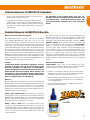
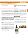
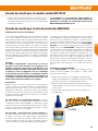
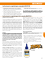
Dieses Modell ist nicht aus Styropor™! Daher sind Verklebungen mit
Weißleim, Polyurethan oder Epoxy nicht möglich.Diese Kleber haften
nur oberächlich und können im Ernstfall abplatzen. Verwenden Sie nur
Cyanacrylat-/Sekundenkleber mittlerer Viskosität, vorzugsweise Zacki2-
ELAPOR
®
# 1-01291, der für ELAPOR
®
Partikelschaum optimierte und
angepasste Sekundenkleber. Bei Verwendung von Zacki2-ELAPOR
®
können Sie auf Kicker oder Aktivator weitgehend verzichten. Wenn
Sie jedoch andere Kleber verwenden, und auf Kicker/Aktivator nicht
verzichten können, sprühen Sie aus gesundheitlichen Gründen nur im
Freien. Vorsicht beim Arbeiten mit allen Cyanacrylatklebern. Diese Kleber
härten u. U. in Sekunden, daher nicht mit den Fingern und anderen
Körperteilen in Verbindung bringen. Zum Schutz der Augen unbedingt
Schutzbrille tragen! Von Kindern fernhalten! An einigen Stellen ist es auch
möglich Heißkleber zu verwenden. Hierauf weisen wir in der Anleitung
ggf. hin!
Arbeiten mit Zacki2-ELAPOR
®
Zacki2-ELAPOR
®
wurde speziell für die Verklebung für unsere
Schaummodelle aus ELAPOR
®
entwickelt. Um die Verklebung möglichst
optimal zu gestalten, sollten Sie folgende Punkte beachten:
• Vermeiden Sie den Einsatz von Aktivator. Durch ihn wird die Verbin-
dung deutlich geschwächt. Vor allem bei großächiger Verklebung
empfehlen wir, die Teile 24 Stunden trocken zu lassen.
• Aktivator ist lediglich zum punktuellen Fixieren zu verwenden. Sprü-
hen Sie nur wenig Aktivator einseitig auf. Lassen Sie den Aktivator
ca. 30 Sekunden ablüften.
• Für eine optimale Verklebung rauen Sie die Oberäche mit einem
Schleifpapier (320er Körnung) an.
chenden“ Folgeschäden bei späteren Flügen zu technischem und
Materialversagen und Abstürzen führen.
• Feuergefahr durch Fehlfunktion der Elektronik: Akkus sind sicher
aufzubewahren. Sicherheitshinweise der Elektronikkomponenten im
Modell, des Akkus und des Ladegeräts sind zu beachten. Elektronik
ist vor Wasser zu schützen. Regler und Akkus müssen ausreichend
gekühlt werden.
Die Anleitungen unserer Produkte dürfen nicht ohne aus-
drückliche Erlaubnis der Multiplex Modellsport GmbH & Co. KG
(in schriftlicher Form) - auch nicht auszugsweise in Print- oder
elektronischen Medien reproduziert und / oder veröffentlicht
werden.
# 1-01291
DE

4
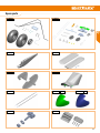
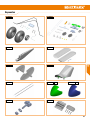
Zubehör und Werkzeug
Technische Daten
Benötigtes Zubehör
Optionales Zubehör
Lieferumfang FunCub NG RR
Benötigtes Werkzeug
Spannweite 1410 mm
Länge über alles 1050 mm
Fluggewicht 1380 g
Flächeninhalt 39,9 dm²
Flächenbelastung 34,6 g/dm²
RC-Funktionen Querruder, Höhenruder, Seitenruder, Motor
Landeklappen, optional Schleppkupplung
• 1 x Zacki2 Elapor
®
20g # 1-01291
• 1 x Zackivator - Aktivator für Zacki und CA Kleber # 1-01032
• 1 x Empfänger RX-7-DR light M-LINK 2,4 GHz # 55810
• 1 x ROXXY EVO LiPo 3 - 2600M 40C mit/with BID-Chip
# 316656
Bei Verwendung der Schleppkupplung empfehlen wir:
• 1 x Empfänger RX-9 DR M-Link 2,4 GHz
(anstelle des RX-7)
# 55812
• 1 x mittelgroßer Schlitzschraubendreher
• 1 x kleine Flachzange
• 1 x Inbusschlüssel 1,5mm (liegt bei)
• 1 x 10mm Gabel- oder Steckschlüssel
• 1 x Bogen Schleifpapier Körnung 240-320
• 1 Elapor
®
Modell (fast fertig gebaut)
• 1 Antriebsmotor ROXXY BL C35-42-930 # 1-01484
• 1 Regler ROXXY BL-Control 740 S-BEC # 1-01317
• 4 Servos Hitec HS-55+ # 1-01205
• 2 Servos Hitec HS-65HB # 112065
• 1 Propeller 13x4 # 733114
• 1 x Cockpit SX Telemetrieset # 25161
• 1 x Schwimmersatz FunCub # 1-01539
• 1 x Schwimmersatz FunCub NG blau # 1-01585
• 1 x Servo 55+ für Schleppkupplung # 1-01205
• 1 x POWER-MULTIlight # 73030
• 1 x Lipochecker # 118380
• 1 x Hitec Multicharger X1 Red # 114131
• 1 x Wingstabi 7 Channel # 55010
• 1 x Wingstabi RX 7 DR # 55012
• 1 x Propeller- Wuchtgerät # 332355
DE

5
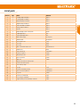
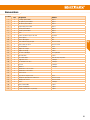
Stückliste
lfd. Nr Stück Bezeichnung Material
1 1 Rumpf fertig montiert Elapor
2 1 Tragäche links fertig montiert Elapor
3 1 Tragäche rechts fertig montiert Elapor
4 1 Höhenleitwerk fertig montiert Elapor
5 1 Seitenleitwerk fertig montiert Elapor
6 1 Kabinenhaube fertig montiert Elapor
7 1 Spinner Elapor
8 1 Gegenplatte Fahrwerksaufnahme Kunststoff
9 2 Leichträder EPP
10 1 Superleichtrad EPP
11 1 Hauptfahrwerk Federstahl
12 1 Spornraddraht Federstahl
13 4 Kreuzschlitzschrauben Stahl
14 4 Stellringe Messing
15 1 Stellring Messing
16 2 Linsenkopfschrauben Stahl verzinkt
17 1 Rohrniete Messing
18 2 Dekor Seitenleitwerk Folie geplottet
19 1 Halter für Spinner Kunststoff
20 2 Tragächenbefestigungsschrauben Kunststoff
21 1 Schleppkupplung Kunststoff
22 1 Multitool Kunststoff
23 2 Klettband Pilzkopf
24 2 Klettband Velours
25 1 Klettschlaufe
26 1 Inbusschlüssel Stahl
27 2 Höhen- und Seitenrudergestänge Federstahl
28 1 Schleppkupplungsgestänge Federstahl
29 1 Propeller Kunststoff
30 1 Anleitung FunCub NG Papier
31 1 Reklamationsbearbeitung Papier
32 1 Beiblatt Kenntnisnachweis Papier
DE

6
Bauanleitung
Vor dem Bau
Überprüfen Sie die gelieferten Teile auf ihre Vollständigkeit anhand der
Stückliste auf Seite 4 und 5. Wir empfehlen eine weiche, saubere und
gerade Unterlage, damit das Modell beim Bau keine Macken bekommt.
Verwenden Sie, wenn nicht ausdrücklich anders angegeben, zum
Verkleben des Modells Zacki2 Elapor
®
CA-Sekundenkleber. Um eine
optimale Verklebung zu erreichen sollten Sie die Kontaktächen mit feinem
Schleifpapier (Körnung 240-320) vorher anschleifen. Das gilt sowohl für
Schaum-Schaum als auch für Schaum-Kunststoff Verklebungen.
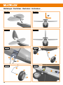
1. Montage des Höhenleitwerks
Setzen Sie das Höhenleitwerk probehalber auf den Rumpf, um die
Passung und den rechtwinkligen Sitz zu kontrollieren
Abb. 1
.
Wenn
alles passt, kann das Leitwerk wieder abgenommen werden. Schleifen
Sie nun die Kontaktächen etwas an und tragen danach den Kleber auf
die Auageäche auf. Fügen Sie nun das Höhenleitwerk und den Rumpf
zusammen. Austretenden Klebstoff können Sie mit einem Papiertuch
abwischen. Kontrollieren Sie, ob das Leitwerk gerade sitzt und justieren
Sie es ggf.
Abb. 2
.
2. Montage des Seitenleitwerks
Gehen Sie beim Seitenleitwerk analog zum Höhenleitwerk vor
Abb. 3
.
Zuerst den winkligen Sitz testen, anschleifen, Kleber auftragen,
zusammenfügen und ausrichten
Abb. 4
. Kleben Sie anschließend noch
die fehlenden Dekorelemente
auf das Seitenleitwerk.
3. Montage des Fahrwerks
Wie auf
Abb. 5
gezeigt, wird das Hauptfahrwerk
, mit Hilfe der
Gegenplatte
und den 4 Schrauben
unter den Rumpf geschraubt.
Schieben Sie auf jeder Seite der Radachsen je ein Stellring
auf und
ziehen Sie die Madenschrauben an
Abb. 6
. Es folgen die Räder
und nochmals auf jeder Seite ein Stellring
zur Sicherung. Die Räder
sollten sich dabei noch leicht drehen lassen. Beim Spornfahrwerk wird
zuerst die Rohrniete
mit der dünnen Seite voraus auf den Sporndraht
aufgefädelt
Abb. 7
. Schieben Sie das Spornrad
auf und
sichern Sie es mit dem Stellring
. Die ganze Einheit wird von unten
durch die Scharniere gesteckt und mit den Linsenkopfschrauben
festgeschraubt
Abb. 8
.
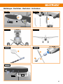
4. Montage von Höhenruder und Seitenrudergestänge
Die Gestänge
werden nach
Abb. 8/9
eingehängt. Stellen Sie die
Servos in die Mittenposition und die Ruder in die Neutralstellung. Ziehen Sie
nun die Madenschrauben mit dem beiliegenden Inbusschlüssel
fest.
5. Einbau der optionalen Schleppkupplung
Die Schleppkupplung
kann jederzeit nachgerüstet werden. Kleben
Sie diese, in die dafür vorgesehene Aussparung der rechten Tragäche
ein
Abb. 10
.
. Die Servotasche ist für ein HS-55+ vorbereitet. Das
Servo wird mit Zacki2 ELAPOR
®
eingeklebt. Das Gestänge muss dem
verwendeten Servohebel angepasst werden. Biegen Sie das Gestänge mit
einer kleinen Flachzange zurecht. Am besten ist es, wenn das Gestänge
soweit innen wie möglich am Servohebel eingehängt ist. Bringen Sie
nun die Schleppkupplung in die „Zu“ Position und schneiden dann den
überschüssigen Draht bündig an der Oberseite ab. Der Draht sollte noch
mit etwas Schleifpapier oder einer Feile an der Schnittkante entgratet
werden.
6. Empfängereinbau
Der Empfänger hat seinen Platz hinter der Fahrwerksaufnahme.
Abb. 11
Dieser Platz ist zu allen Modellachsen winkelig und somit ideal geeignet,
um ein Wingstabi dort zu installieren. Stecken Sie zuerst die Servos an
den Empfänger und kleben Sie diesen mit je einem Stück Klettband
an seinen Platz. Markieren Sie am besten einen der beiden grünen
Hochstromstecker und sein Gegenstück (z.B. mit einem Filzstiftpunkt).
Somit vermeiden Sie Verwechselungen beim Aufbau des Modells.
Wichtig: Bei der Positionierung der Antennen ist darauf zu achten,
dass sie nicht durch den Akku, Regler oder Kabel abgeschattet
werden können.
7. Flächenstreben montieren
Montieren Sie die Tragäche auf den Rumpf, indem Sie zuerst die
Hochstromstecker verbinden und dann die Tragäche auf dem Rumpf
positionieren, überprüfen Sie vor dem Festschrauben der Tragäche die
korrekte Funktion der Ruder. Schrauben Sie nun mit dem beiliegenden
Multitool
oder einem passenden Schlitzschraubendreher die
beiden Flächenbefestigungsschrauben
fest. Bei der Einstellung der
Strebenlänge sollte auf keinen Fall die jetzt entstandene V-Form der
Tragäche verändert werden
Abb. 12
. Hängen Sie die Streben an der
Tragäche ein. Die unteren Gabelköpfe werden nun so eingestellt, das
sie sich ohne Spannung ein-und aushängen lassen. Verwenden Sie zum
Öffnen der Gabelköpfe das mitgelieferte Multitool
Abb. 13
. Ist die
richtige Länge der Strebe ermittelt, werden die unteren Gabelköpfe mit den
vorher aufgeschraubten M2 Muttern gekontert. Als zusätzliche Sicherung
können Sie auch noch einen Tropfen Sekundenkleber aufbringen.
8. Programmieren der Ruderausschläge
Vorsicht: Alle Programmierarbeiten sollten bei demontiertem
Propeller erfolgen. Wahlweise können auch die Motorkabel getrennt
werden. Ein ungewollt anlaufender Motor hat ein sehr hohes
Gefahrenpotenzial!!!
Die Ruderausschläge sollten wie folgt eingestellt werden:
Querruder: +22 mm / -12 mm
Höhenruder: +25 mm / -22 mm
Seitenruder: + 28 mm / - 28 mm
Landeklappen: Startstellung -12 mm
Landestellung -75 mm mit -12 mm Höhenruder zugemischt
Wichtig: Die Servos dürfen auf gar keinen Fall bei Vollausschlag
auf den Anschlag laufen. Achten Sie auch auf Leichtgängigkeit der
Scharniere und der Gestängeanschlüsse. Eine Überlast kann die
Servos beschädigen.
DE

7
Bauanleitung
9. Montage des Propellers
Stecken Sie den Distanzring und danach den Propeller
auf den
Propellermitnehmer
Abb. 14
. Schieben Sie den Spinnerhalter
auf
und schrauben Sie mit der Unterlegscheibe und der Mutter das Ganze fest.
Zum Schluss wird noch der Spinner
aufgesteckt und gegebenenfalls
die Motorsteckverbindungen wieder hergestellt.
Sollte der Antrieb zu stark vibrieren, sollten Sie den Propeller mit unserem
Propellerwuchtgerät #332355 oder ähnlichem Gerät nachwuchten.
10. Vorflugkontrolle und Schwerpunkt
Kontrollieren Sie das Modell, bevor Sie es das erste Mal iegen lassen.
Folgende Punkte gibt es zu beachten:
• sind die Ruderhörner fest?
• sind die Servoschrauben angezogen (Kreuzschlitzschrauben)?
• sind alle Anlenkungsgestänge funktionsfähig (Madenschrauben)?
• ist der Propeller richtig angezogen?
• läuft der Spinner rund? (von Hand den Propeller drehen und Spalt
zwischen Rumpf und Spinner beobachten)
• kontrollieren Sie nochmals die Servodrehrichtungen
Legen Sie nun den Akku (3S-2600mAh 40C) auf die Akkuauage und
legen die Klettschlaufe um ihn.
So kann er bei der Einstellung des Schwerpunktes leicht verschoben
werden. Dieser liegt bei 82mm hinter der Nasenleiste (in Rumpfnähe)
Abb. 15
. An dieser Stelle sind kleine Noppen unter der Tragäche
angeschäumt. Montieren Sie noch die Kabinenhaube auf den Rumpf und
balancieren das Modell mit ihren Zeigengern auf den Noppen.
Das Modell sollte sich jetzt mit leicht gesenkter Nase auspendeln.
Verschieben Sie den Akku solange, bis der Schwerpunkt richtig eingestellt
ist. Markieren Sie sich die Lage des Akkus auf der Akkuauage, um
nach einem Wechsel wieder die richtige Position zu nden. Mit je einem
Streifen Klettband
unter dem Akku ist er nun sicher xiert.
Dem Erstug steht jetzt nichts mehr im Weg.
Wir wünschen Ihnen viel Spaß und tolle Flüge mit Ihrem neuen Modell!
Das Multiplex Modellsport Team
DE

8
Artikel Nr. Bezeichnung
# 1-01426 Rumpf FunCub NG gebaut (ohne RC und Dekor)
# 1-01427 Tragächen FunCub NG gebaut (ohne RC und Dekor)
# 1-01428 Leitwerke FunCub NG gebaut (ohne Dekor)
# 1-01429 Kabinenhaube FunCub NG gebaut (ohne Dekor)
# 1-01430 Flächenstreben FunCub NG
# 1-01431 Spinner FunCub NG grün
# 1-01518 Spinner FunCub NG blau
# 1-01432 Propellermitnehmer FunCub NG
# 1-01433 Kleinteilesatz FunCub NG
# 1-01060 Dekorbogen FunCub NG A und B
# 1-01477 Fahrwerkssatz FunCub NG
# 1-01492 Fahrwerkshalter FunCub NG
# 224441 Offset-Scharniersatz FunCub XL
# 733114 Luftschraube 13x4
# 733198 Räder superleicht Ø 120mm
# 733189 Spornrad Ø 54
# 713340 Kunststoffschrauben M5X50 10 Stück
# 725136 Canopy Lock 2 Paar
# 683112 Klettband Abschnitte 5 Stück
# 1-01484 Motor ROXXY BL C35-42-930 KV (nur dieser passt in die FunCub NG)
# 1-01317 Regler ROXXY BL Control 740 S-BEC
# 1-01205 HS 55+
# 112065 HS 65 HB
# 1-01516 Dekorbogen FunCub NG blau A und B
# 1-01518 Spinner FunCub NG blau
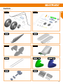
Ersatzteile
DE

9
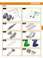
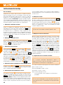
Ersatzteile
# 1-01426 # 1-01427
# 1-01428 # 1-01429
# 1-01430
# 1-01432
# 1-01433# 1-01477
# 1-01492
# 1-01431 # 1-01518grün blau
DE

10
When operating the model, all warning and safety information in
the operating instructions must be observed.
The model is NOT A TOY in the conventional sense. If you use your model
carefully, it will provide you and your spectators with lots of fun without
posing any danger. If you do not operate your model responsibly, this may
lead to signicant property damage and severe injury. You and you alone
are responsible for following the operating instructions and for ensuring
the safety guidelines are adhered to.
When setting up the model, operators declare they are familiar with
and understand the contents of the operating instructions, particularly
regarding safety information, maintenance work, operating restrictions,
and deciencies.
This model may not be operated by children under the age of 14. If minors
operate the model under the supervision of a responsible and competent
adult pursuant to the law, this person is responsible for adhering to the
information in the operating instructions.
THE MODEL AND THE ASSOCIATED ACCESSORIES MUST BE KEPT OUT
OF REACH OF CHILDREN UNDER 3 YEARS OF AGE! CHILDREN UNDER 3
COULD SWALLOW REMOVABLE SMALL PARTS OF THE MODEL. RISK OF
SUFFOCATION!
Multiplex Modellsport GmbH & Co. KG is not liable for loss, damage
and consequential damage of any kind caused by incorrect operation,
improper use or misuse of this product, including the accessories used
along with it.
Proper use
The model may only be used in the hobby sector. No other type of use
is permitted. To operate the model, only the accessories recommended
by Multiplex may be used. The recommended components have been
tested and adjusted for safe functioning together with the model. If other
components are used or the model is modied, all claims against the
manufacturer or retailer are void.
In order to minimize the risk when operating the model, observe the
following points in particular:
• The model is controlled via a remote control. No remote control
is safe from radio interference. Interference may lead to a loss of
control of the model. Therefore, always ensure large safety distanc-
es in all directions when operating the model. As soon as even the
smallest indication of radio interference presents itself, operation of
the model must be halted immediately!
• The model may only be put into operation after a complete function
and range test has been successfully carried out as per the instruc-
tions for the remote control.
• The model may only be own in good visibility. Do not y in poor light
or in the direction of the sun in order to avoid glare.
• The model may not be operated under the inuence of alcohol or
other intoxicants. The same applies for medicines that impair percep-
tion and responsiveness.
• Only y the model in wind and weather conditions in which you can
safely control it. Even with light wind, take into account that turbu-
lence may build up on objects and have an effect on the model.
• Never y in places where this would pose a danger to others, i.e. in
residential areas, near power lines, roads, and railroad tracks.
• Never direct the model at people or animals! Avoid unnecessary risks
and alert other pilots to potential hazards. Always y in a manner that
ensures neither you nor others are exposed to danger – even many
years of accident-free ying experience are no guarantee for the next
minute of ying time.
Residual risks
Even if the model is operated in accordance with the regulations and
observing all safety aspects, there is always a residual risk.
Third-party liability insurance (powered model airplane) is therefore
mandatory. If you are a member of a group or association, you might be
able to take out the appropriate insurance there.
Ensure models and the remote control are properly maintained and are in
good condition at all times.
Due to the construction and design of the model, the following dangers
may arise in particular:
Injuries caused by the propeller: As soon as the battery is connected, the
area around the propeller must be kept clear. Be aware that objects in
front of the propeller may be sucked in and objects behind the propeller
may be blown away. Always align the model ensuring it cannot move in
the direction of other people if the motor starts up unintentionally. When
performing adjustments for which the motor is running or may start up,
the model must always be securely held in place by a helper.
• Crashes caused by control errors: Even the most experienced pilots
can make mistakes. For this reason, only y in a safe environment
and at authorized model airplane ying elds.
• Crashes caused by technical failures, undetected damage from
transportation or pre-existing damage: The model must be carefully
inspected before each ight. Bear in mind that technical or material
failures may occur at any time. Therefore, only operate the model in a
safe environment.
• Adhere to operating limits: Excessively harsh ying weakens the
structure of the model and may lead to technical and material fail-
ures as well as crashes immediately or, due to 'insidious' consequen-
tial damage, in later ights.
• Risk of re due to malfunction of the electronics: Batteries must be
stored safely. The safety information of the electronic components in
the model, the battery, and the charging device must be observed.
Safety information for MULTIPLEX airplane models
EN

11
Familiarize yourself with the construction kit!
MULTIPLEX model kits are subjected to constant material inspection
during production. We hope that you are satised with the contents of the
kit. We nevertheless ask that you check all parts (according to the parts
list) before use, as used parts cannot be exchanged. If a part is not OK,
we will be happy to x or replace it after verifying this. Please send the
part with sufcient postage to our Service department. Be sure to include
a short description of the fault along with the purchase receipt. We are
continuously working on further developing the technology of our models.
We reserve the right to make changes to the contents of the kit in terms
of shape, dimension, technology, material, and equipment at any time and
without warning. Please understand that no claims can be derived from
specications and illustrations in these instructions.
Caution!
Remote-controlled models, particularly airplane models, are not
toys in the conventional sense. Their construction and operation
requires technical understanding, a minimum level of artisan
skills, discipline, and safety-awareness. Errors and negligences
during building and operation may result in personal injury or
property damage. As the manufacturer has no influence on
proper assembly, maintenance, and operation, we explicitly refer
to these dangers.
Warning:
Like any airplane, the model has static limitations! Nosedives and reckless
maneuvers may result in damage to the model. Please note: In such
cases, there is no replacement. Approach the limitations with caution.
The model is tted with the propeller recommended by us but can only
withstand the loads if it is built awlessly and is undamaged.
Crooked – does not really exist. If individual parts are bent during
transit, they can be straightened again. Here, ELAPOR
®
behaves like
metal. If you overbend the material slightly, it springs back minimally and
retains its shape. The material of course has its limits – so don’t overdo it!
Crooked
–
does indeed exist! If you want to paint your model, you do
not need any primer for pretreatment when using the EC colors. Matt
paints result in the best look. Under no circumstances may the paint coats
be too thick or applied unevenly, otherwise the model will go out of shape
and will be crooked, heavy or even unusable!
This model is not made of Styrofoam™! Therefore, adhesions using
white glue, polyurethane or epoxy are not possible. These glues only stick
supercially and may peel off in severe cases. Only use cyanoacrylate/
superglue of medium viscosity, preferably Zacki2-ELAPOR
®
# 85 2727,
the superglue optimized and adapted for ELAPOR
®
particle foam. When
using Zacki2-ELAPOR
®
, you can largely do without kickers or activators.
If, however, you use other adhesives, and are unable to do without
kickers/activators, only spray outdoors for health reasons. Take care when
working with all cyanoacrylate adhesives. These adhesives sometimes
harden in seconds, so do not bring your ngers or other body parts
into contact with them. To protect your eyes, be sure to wear protective
goggles! Keep away from children! In some places, hot glue may also be
used. If applicable, this is indicated in the instructions!
Working with Zacki2 ELAPOR
®
Zacki2 ELAPOR
®
was developed specially for adhesion on our foam
models made of ELAPOR
®
. In order to design the adhesion as optimally
as possible, the following points should be taken into consideration:
• Avoid the use of activators. This causes the bonding to be signicant-
ly weakened. Especially for large-scale adhesion, we recommend
allowing 24 hours for the parts to dry.
• Activators must only be used for point xing. Only spray a little
activator on one side. Allow the activator to ash off for approx. 30
seconds.
• For optimal bonding, sand down the surface using sandpaper (grain
size 320).
The electronics must be protected from water. The controller and the
batteries must be sufciently cooled.
The instructions of our products may not be reproduced and/or
published – not even in part – in print or electronic media without
the express (written) permission of Multiplex Modellsport GmbH
& Co. KG.
Safety information for MULTIPLEX airplane models
Safety information for MULTIPLEX construction kits
# 1-01291
EN

12
Scope of delivery FunCub NG RR
Accessories and tools
Required accessories Required tool
Optional accessories
• 1 Elapor
®
model (almost fully assembled)
• 1 drive motor ROXXY BL C35-42-930 # 1-01484
• 1 controller ROXXY BL Control 740 S-BEC # 1-01317
• 4 servo Hitec HS-55+ # 1-01205
• 2 servo Hitec HS-65HB # 112065
• 1 propeller 13x4 # 733114
Specications
Wingspan 1410 mm
Overall length 1050 mm
Flight weight 1380 g
Wing area 39.9 dm²
Wing loading 34.6 g/dm²
RC functions Aileron, elevator, rudder, motor,
landing aps, optional aero-tow release
• 2 x Zacki2 ELAPOR
®
20g # 1-01291
• 1x Zackivator - activator for Zacki and CA adhesive # 1-01032
• 1 x receiver RX-7-DR light M-LINK 2.4 GHz # 55810
• 1 x ROXXY EVO LiPo 3 - 2600M 40C with BID chip
# 316656
When using aero-tow release, we recommend:
• 1 x receiver RX-9-DR M-LINK 2.4 GHz
(instead of RX-7)
# 55812
• 1 x medium-sized slotted screwdriver
• 1 x small at nose pliers
• 1 x hex wrench 1.5 mm (included)
• 1 x 10 mm open-ended wrench or socket wrench
• 1 x sheet of 240-320 grit sandpaper
• 1 x cockpit SX telemetry set # 25161
• 1 x oat kit FunCub # 1-01539
• 1 x oat kit FunCub NG blue # 1-01585
• 1 x servo 55+ for aero-tow release # 1-01205
• 1 x POWER-MULTIlight # 73030
• 1 x LiPo checker # 118380
• 1 x Hitec multi charger X1 red # 114131
• 1 x Wingstabi 7 channel # 55010
• 1 x Wingstabi RX 7 DR # 55012
• 1 x propeller balancer # 332355
EN

13
List of parts
Serial no.
Qty. Name Material
1 1 Fuselage fully assembled Elapor
2 1 Left wing fully assembled Elapor
3 1 Right wing fully assembled Elapor
4 1 Tailplane fully assembled Elapor
5 1 Vertical tail fully assembled Elapor
6 1 Canopy fully assembled Elapor
7 1 Spinner Elapor
8 1 Undercarriage mount counter plate Plastic
9 2 Lightweight wheel EPP
10 1 Super lightweight wheel EPP
11 1 Main undercarriage Spring steel
12 1 Tailwheel wire Spring steel
13 4 Cross-head screw Steel
14 4 Set collar Brass
15 1 Set collar Brass
16 2 Oval countersunk head screw Galvanized steel
17 1 Tubular rivet Brass
18 2 Vertical tail decal Plotted lm
19 1 Holder for spinner Plastic
20 2 Wing xing screws Plastic
21 1 Aero-tow release Plastic
22 1 Multi-tool Plastic
23 2 Mushroom head hook and loop tape
24 2 Velour hook and loop tape
25 1 Hook and loop strap
26 1 Hex key Steel
27 2 Elevator and rudder pushrod Spring steel
28 1 Aero-tow release pushrod Spring steel
29 1 Propeller Plastic
30 1 Instructions FunCub NG Paper
31 1 Processing of complaints Paper
32 1 Supplementary sheet knowledge certicate Paper
EN

14
Assembly instructions
Before assembly
Check completeness of the parts supplied using the list of parts on pages
12 and 13. We recommend using a soft, clean and at surface to ensure
the model is not damaged during assembly. Always use, unless otherwise
specically stated Zacki2 Elapor
®
CA instant adhesive to glue the model.
To ensure optimum bonding, use ne sandpaper (grain size 240-320) to
sand the contact surfaces in advance. This applies both to foam-foam and
foam-plastic bonding.
1. Assembling the tailplane
Place the tailplane on the fuselage to check the t and that it is at a
right angle to the fuselage
Fig. 1
.
If everything ts, the elevator can be
removed again. Now sand the contact surfaces slightly and then apply
adhesive to the contact surface. Now join the tailplane and the fuselage
together. Use a paper towel to wipe off any escaping adhesive. Check that
the elevator is straight and, if necessary, adjust its position
Fig. 2
.
2. Assembling the vertical tail
Proceed with the vertical tail in the same way as with the tailplane
Fig. 3
.
Initially check that it is at a right angle, sand, apply adhesive, join together
and adjust
Fig. 4
. Then stick the missing decal elements
onto the
vertical tail.
3. Assembling the undercarriage
As shown in
Fig. 5
, screw the main undercarriage
, using the
counter plate
and the 4 screws
, underneath the fuselage. Slide
a set collar
on each side of the wheel axles and tighten the grub
screws
Fig. 6
. Then install the wheels
and another set collar
on each side to ensure correct attachment. It should still be possible to
turn the wheels easily. With the tail undercarriage, initially thread the thin
side of the tubular rivet
onto the tailwheel wire
Fig. 7
. Slide on
the tailwheel
and secure it with the set collar
. The whole unit
is inserted through the hinges from below and tightened with the oval
countersunk head screws
Fig. 8
.
4. Assembling the elevator and the rudder pushrod
The roods
are hooked in according to
Fig. 8 / 9
. Place the
servos in
the center position and the rudders in the neutral position. Now tighten
the
grub screws using the included hex wrench
.
5. Installing the optional aero-tow release
The aero-tow release
can be retrotted at any time. Glue it into the
recess on the right wing provided for this purpose
Fig. 10
.
. The servo
pocket is prepared for a HS-55+. Glue the servo into place with Zacki2
ELAPOR
®
. The pushrod must be adapted to the servo arm used. Use
small at nose pliers to bend the pushrod to the desired shape. It is best
if the pushrod is hooked into the servo arm as far inside as possible. Now
move the aero-tow release to the “closed” position and cut off the excess
wire ush at the top. Use sandpaper or a le to deburr the wire at the
cutting edge.
6. Installing the receiver
The receiver is located behind the undercarriage mount.
Fig. 11
This
space is at an angle to all model axes and is therefore the ideal location
for installing a Wingstabi. First plug the servos into the receiver and then
x it into place with a piece of hook and loop tape
. Mark one of
the two green high-current connectors and its counterpart (e.g. with a felt
tip pen). This ensures there is no confusion when assembling the model.
Important: When positioning the antennas, make sure that they
cannot be shadowed by the battery, controller or cable.
7. Assembling wing struts
Assemble the wing on the fuselage by rst connecting the high-current
connectors and then positioning the wing on the fuselage; make sure
the rudders are working correctly before tightening the wing. Now use
the included multi-tool
or a suitable screwdriver to tighten the two
wing xing screws
. The created V-shape of the wing should never be
altered when adjusting the strut length
Fig. 12
. Hook the struts into the
wing. Now adjust the lower fork heads so that they can be hooked in and
out without tension. Open the fork heads using the supplied multi-tool
Fig. 13
. Once the correct length of the strut has been determined, the
lower fork heads are locked into place with the previously screwed on M2
nuts. You can also apply a drop of instant adhesive for additional security.
8. Programming the rudder deflections
Caution: Carry out all programming work with the propeller
disassembled. Optionally, the motor cables can also be disconnected.
Unintentional start-up of the motor poses a high hazard potential!!!
Set the rudder deections as follows:
Aileron: +22 mm / -12 mm
Elevator: +25 mm / -22 mm
Rudder: +28 mm / -28 mm
Landing flaps: Starting position -12 mm
Landing position -75 mm with -12 mm elevator mixed in
Important: The servos must under no circumstances run to the
stop at full deection. Also make sure that the hinges and pushrod
connectors run smoothly. An overload may damage the servos.
EN

15
Assembly instructions
9. Assembling the propeller
Position the spacer ring and then the propeller
on the propeller driver
Fig. 14
. Slide on the spinner holder
and screw everything tight using
the washer and the nut. Finally insert the spinner
and, if necessary,
reconnect the motor plug-in connections.
If the drive vibrates excessively, balance the propeller using our propeller
balancer #332355 or a similar device.
10. Preflight check and center of gravity
Always check the model before ying it for the rst time. Pay attention to
the following points:
• Are the rudder horns tight?
• Have the servo screws been tightened (cross-head screws)?
• Are all the linkage pushrods working correctly (grub screws)?
• Has the propeller been tightened properly?
• Is the spinner running true? (Rotate the propeller by hand and ob-
serve the gap between the fuselage and the spinner)
• Check the directions of rotation of the servo again
Place the battery (3S-2600mAh 40C) on the battery support and wrap the
hook and loop strap around it.
This allows you to move it easily when adjusting the center of gravity.
This should be set to 82 mm behind the leading edge (near the fuselage)
Fig. 15
. At this point small bumps are foamed underneath the wing.
Assemble the canopy on the fuselage and balance the model with your
index ngertips on the bumps.
The model should now balance level with its nose slightly lowered. Move
the battery until the center of gravity has been set correctly. Mark the
location of the battery on the battery support to ensure that it is always
replaced in the same position. One strip of both types of hook and loop
tape
underneath the battery will hold it securely in place.
Now nothing stands in the way of the maiden ight.
We hope you enjoy it and wish you lots of fun ying your new model!
The Multiplex Modellsport Team
EN

16
Spare parts
In case something goes wrong…
Item no. Name
# 1-01426 Assembled fuselage FunCub NG (without RC and decals)
# 1-01427 Assembled wings FunCub NG (without RC and decals)
# 1-01428 Assembled tail units FunCub NG (without decals)
# 1-01429 Assembled canopy FunCub NG (without decals)
# 1-01430 Wing struts FunCub NG
# 1-01431 Spinner FunCub NG, green
# 1-01518 Spinner FunCub NG, blue
# 1-01432 Propeller driver FunCub NG
# 1-01433 Set of small parts FunCub NG
# 1-01060 Decal sheet FunCub NG A and B
# 1-01477 Undercarriage kit FunCub NG
# 1-01492 Undercarriage mount FunCub NG
# 224441 Offset hinge set FunCub XL
# 733114 Propeller 13x4
# 733198 Super lightweight wheels Ø 120 mm
# 733189 Tailwheel Ø 54
# 713340 Plastic screws M5X50 (x10)
# 725136 Canopy lock 2 pairs
# 683112 Hook and loop tape sections (x5)
# 1-01484 Motor ROXXY BL C35-42-930 KV (only this motor ts in the FunCub NG)
# 1-01317 Controller ROXXY BL control 740 S-BEC
# 1-01205 HS 55+
# 112065 HS 65 HB
# 1-01516 Decal sheet FunCub NG blue A and B
# 1-01518 Spinner FunCub NG, blue
EN

17
# 1-01426 # 1-01427
# 1-01428 # 1-01429
# 1-01430
# 1-01432
# 1-01433# 1-01477
# 1-01492
# 1-01431 # 1-01518
Spare parts
green blue
EN

18
Conseils de sécurité pour les modèles volants MULTIPLEX
Lors de l’utilisation de ce modèle, veuillez respecter impérative-
ment tous les avertissements et consignes de sécurité.
Ce modèle N’EST PAS UN JOUET au sens propre du terme. Utilisez votre
modèle avec sérieux et prudence. Vous ferez ainsi le bonheur de vos
spectateurs sans provoquer de dangers. L’utilisation irraisonnée de ce
modèle peut entraîner des dommages matériels majeurs et des blessures
graves. Charge à vous de suivre cette notice de construction et de mettre
en pratique les consignes de sécurité.
En utilisant son modèle, l’utilisateur déclare avoir pris connaissance et
compris le contenu de cette notice, notamment à propos des consignes
de sécurité, travaux de maintenance, limitations d’utilisation et défauts.
Ce modèle ne peut être utilisé par des enfants de moins de 14 ans. En
cas d’utilisation du modèle par un mineur sous la surveillance d’un adulte
responsable et bien informé au sens de la législation, ce dernier répond
de l’application des consignes gurant dans cette notice.
VEUILLEZ TENIR CE MODÈLE ET SES ACCESOIRES HORS DE PORTÉE
DES ENFANTS DE MOINS DE 3 ANS ! LES ENFANTS DE MOINS DE 3 ANS
POURRAIENT AVALER LES PETITES PIÈCES AMOVIBLES DU MODÈLE.
RISQUE D’ÉTOUFFEMENT !
Multiplex Modellsport GmbH & Co. KG décline toute responsabilité en cas
de perte, dommages et dommages consécutifs de toute nature, dus à une
utilisation erronée, à une utilisation non conforme ou inappropriée de ce
produit, y compris les accessoires utilisés avec ce dernier.
Utilisation conforme
Ce modèle est exclusivement destiné à être utilisé pour les loisirs. Toute
autre utilisation est interdite. Ce modèle ne peut être utilisé qu’avec
les accessoires recommandés par Multiplex. En effet, les composants
recommandés ont été testés et adaptés au modèle pour assurer un
fonctionnement en toute sécurité. L’utilisation d’autres composants ou
la modication du modèle entraîne l’extinction de toute prétention auprès
du fabricant, resp. distributeur.
Pour minimiser le risque lié à l’utilisation du modèle, veuillez respecter
les points suivants :
• Ce modèle se pilote à l’aide d’une radiocommande. Aucune ra-
diocommande n’est entièrement protégée contre les interférences.
Les interférences peuvent entraîner la perte de contrôle du modèle.
Par conséquent, veillez à toujours utiliser votre modèle dans des
espaces entourés d’un grand périmètre de sécurité dans toutes les
directions. Au moindre signe d’interférences, veuillez arrêter immé-
diatement de piloter votre modèle !
• Ensuite, ne réutilisez votre modèle qu’après avoir effectué un contrôle
exhaustif et concluant des fonctions et de la portée de la radiocom-
mande en suivant les instructions fournies avec cette dernière.
• Veuillez piloter ce modèle uniquement si la visibilité est bonne. Ne le
pilotez pas si les conditions de lumière sont difciles et vers le soleil,
cela an d’éviter tout éblouissement.
• Ne pilotez pas ce modèle si vous êtes sous l’emprise de l’alcool et
d’autres stupéants. Ne le pilotez pas non plus si vous prenez des
médicaments limitant votre capacité de perception et vos réexes.
• Ne pilotez votre modèle que dans des conditions de vent et météo
vous permettant de bien le maîtriser. Lorsque le vent est faible,
n’oubliez pas que des turbulences peuvent se former et inuer sur
votre modèle.
• Ne pilotez jamais où vous pourriez vous mettre en danger ou mettre
en danger autrui (par ex. dans des zones d’habitation et près de
lignes haute tension, routes et voies ferrées).
• Ne dirigez jamais votre modèle vers des personnes et des animaux !
Évitez de prendre des risques inutiles et prévenez les autres pilotes
en cas de danger. Pilotez toujours en veillant à ne pas vous mettre en
danger ni à mettre en danger autrui – une expérience de vol de longue
date et sans accident n’est pas une garantie pour votre prochaine
minute de vol.
Risques résiduels
Un risque résiduel persiste même en cas d’utilisation conforme et de
respect de toutes les consignes de sécurité.
Raison pour laquelle vous devez obligatoirement souscrire une assurance
responsabilité civile (aéromodélisme motorisé). Si vous êtes membre
d’un club ou d’une fédération, vous pourrez éventuellement y souscrire
l’assurance correspondante.
Veillez à tout moment au bon entretien et au bon état de fonctionnement
de vos modèles et de votre radiocommande.
Selon son type de construction et sa version, un modèle peut notamment
présenter les risques suivants :
Blessures dues à l’hélice : dès que la batterie est branchée, tenez-vous à
l’écart de la zone d’évolution de l’hélice. Veuillez noter que les objets situés
devant l’hélice sont aspirés et ceux situés derrière, repoussés. Orientez
toujours le modèle de sorte à ce qu’il ne se dirige pas vers les personnes
en cas d’allumage intempestif du moteur. Lors des réglages, moteur en
marche ou pouvant démarrer, demandez toujours à un assistant de tenir
fermement le modèle.
• Crash dû à une erreur de pilotage : même les pilotes les plus aguer-
ris peuvent commettre des erreurs. Volez toujours dans un environ-
nement sûr et sur des terrains autorisés pour le modélisme aérien.
• Crash dû à un problème technique ou à une avarie de transport
/ dommage précédent non détecté : veuillez contrôler avec soins
le modèle avant chaque vol. N’oubliez jamais que des problèmes
techniques ou matériels peuvent se produire à tout moment. Par
conséquent, volez toujours le modèle dans un environnement sûr.
• Respecter les limites : les manœuvres trop brutales affaiblissent la
structure du modèle et peuvent entraîner, soudainement ou en raison
de dommages «latents», des problèmes techniques et des crashs
lors des vols suivants.
• Risque d’incendie dû à une défaillance de l’électronique : conservez
FR

19
Conseils de sécurité pour les modèles volants MULTIPLEX
Conseils de sécurité pour les kits de construction MULTIPLEX
Familiarisez-vous avec le kit d’assemblage !
Les kits d’assemblages MULTIPLEX sont soumis pendant la production
à des contrôles réguliers du matériel. Nous espérons que le contenu
du kit répond à vos attentes. Nous vous prions néanmoins de vérier le
contenu (suivant la liste des pièces) du kit avant l’assemblage, car les
pièces utilisées ne sont pas échangées. Dans le cas où une pièce ne
serait pas conforme, nous sommes disposés à la rectier ou à l’échanger
après contrôle. Veuillez retournez la pièce à notre service sans omettre de
joindre le ticket de caisse ainsi qu’une brève description du défaut. Nous
travaillons en permanence à l’évolution technique de nos modèles. Nous
nous réservons le droit de modier leurs forme, dimensions, technologie,
matériel et équipement sans préavis. Par conséquent, les informations
et les illustrations gurant dans cette notice ne sauraient faire l’objet de
réclamations.
Attention !
Les modèles radiocommandés, surtout volants, ne sont pas
des jouets au sens propre du terme. Leur assemblage et leur
utilisation exigent des connaissances technologiques et un
minimum de dextérité manuelle, de discipline et de respect de
la sécurité. Les erreurs et négligences, lors de la construction
ou de l’utilisation, peuvent conduire à des dommages corporels
ou matériels. Le fabricant du kit n’ayant aucune influence sur
l’assemblage, l’entretien et l’utilisation correcte du modèle, nous
attirons expressément votre attention sur ces dangers.
Avertissement :
Comme tout avion, ce modèle a ses limites liées aux lois physiques !
Les vols en piqué et les manœuvres périlleuses peuvent entraîner la
destruction du modèle. Note : Dans ces cas, nous n’assurerons pas de
remplacement. Veuillez tester les limites du modèle avec précaution.
Ce modèle est conçu pour le moteur que nous recommandons, mais il
ne pourra résister aux contraintes liés au vol que s’il est correctement
assemblé et non endommagé.
Une pièce tordue ? C’est pratiquement impossible. Si certaines
pièces ont été tordues, par exemple pendant le transport, vous pouvez
les redresser. En effet, la matière ELAPOR
®
se comporte plus ou moins
comme le métal. Si vous la tordez légèrement par excès, elle se redresse
par effet ressort et retrouve sa forme initiale. Bien entendu, elle a aussi
ses limites – veillez donc à ne pas exagérer !
Une pièce tordue
?
C’est possible dans certaines conditions ! Si
vous voulez peindre votre modèle, vous n’avez pas besoin d’apprêter
le support si vous utilisez des peintures EC-Color. Esthétiquement,
les peintures mates donnent les meilleurs résultats. En aucun cas les
couches de peinture devront être trop épaisses ou irrégulières. À défaut,
le modèle se dilatera, se cintrera et deviendra lourd, voire inutilisable !
Ce modèle n’est pas réalisé en polystyrène expansé ! Par conséquent,
les assemblages à la colle blanche, polyuréthane ou époxy ne sont pas
possibles. Ces colles n’adhèrent qu’en surface et peuvent éclater en
cas de fortes contraintes. Veuillez n’utiliser que de la colle cyanocrylate/
instantanée de viscosité moyenne, de préférence la Zacki2 ELAPOR
®
# 85 2727, la colle instantanée optimiséepour la mousse de particules
ELAPOR
®
. Avec la colle Zacki2 ELAPOR
®
, l’utilisation d’un accélérateur
ou d’un activateur n’est pas nécessaire. Si néanmoins, vous utilisez une
autre colle associée à un accélérateur/activateur, pour votre santé veillez
à le vaporiser à l’extérieur. Soyez attentif lors de l’utilisation des colles
cyanocrylates. En effet, celles-ci durcissant en quelques secondes vous
devez éviter d’en mettre sur les doigts et sur d’autres parties du corps.
Pour protéger vos yeux, portez impérativement des lunettes ! Tenez-les
hors de portée des enfants ! Pour certains assemblages, vous pouvez
aussi utiliser une colle à chaud. Dans ce cas, veuillez vous référer à la
notice !
Utilisation de la colle Zacki2 ELAPOR
®
La colle Zacki2 ELAPOR
®
a été spécialement développée pour nos
modèles en mousse ELAPOR
®
. Pour optimiser le collage, veuillez
respecter les points suivants :
• N’utilisez aucun activateur. Celui-ci affaiblirait considérablement la
solidité de l’assemblage. Nous recommandons un temps de séchage
de 24 heures surtout pour les collages de grandes surfaces.
• N’utilisez l’activateur que pour une xation ponctuelle. Vaporisez-le
en faibles quantités et sur une seule face. Laissez sécher l’activateur
env. 30 secondes.
• Pour un collage optimal, dépolissez la surface avec du papier de
verre (grain 320).
les batteries dans un endroit sûr. Respectez les consignes de sécuri-
té relatives aux composants électroniques du modèle, de la batterie
et du chargeur. Protégez l’électronique de l’eau. Laissez bien refroidir
le variateur et les batteries.
La reproduction et / ou la publication, même partielle, des
notices relatives à nos produits, dans des médias imprimés ou
électroniques, est interdite sans l’autorisation expresse (écrite)
Multiplex Modellsport GmbH & Co. KG.
# 1-01291
FR

20
Contenu de la livraison FunCub NG RR
Accessoires et outils
Caractéristiques techniques
Accessoires requis Outils requis
Accessoires optionnels
• 1 modèle en Elapor
®
(préassemblé)
• 1 moteur ROXXY BL C35-42-930 Réf. 1-01484
• 1 variateur ROXXY BL-Control 740 S-BEC Réf. 1-01317
• 4 servos Hitec HS-55+ Réf. 1-01205
• 2 servos Hitec HS-65HB Réf. 112065
• 1 hélice 13x4 Réf. 733114
Envergure 1410 mm
Longueur hors tout 1050 mm
Masse en vol 1380 g
Surface alaire 39,9 dm²
Charge alaire 34,6 g/dm²
Fonctions RC Ailerons, profondeur, dérive, moteur,
volets d’atterrissage, crochet en option
• 2 x Zacki2 ELAPOR
®
20g Réf. 1-01291
• 1x Zackivator - activateur pour colle Zacki et colle
instantanée
Réf. 1-01032
• 1 x récepteur RX-7-DR light M-LINK 2,4 GHz Réf. 55810
• 1 x ROXXY EVO LiPo 3 - 2600M 40C avec puce BID
Réf. 316656
Si un crochet est utilisé, nous préconisons:
• 1 x récepteur RX-9-DR M-LINK 2,4 GHz
(au lieu du RX-7)
Réf. 55812
• 1 x tournevis plat moyen
• 1 x petite pince plate
• 1 x clé pour vis six pans creux 1,5mm (fournie)
• 1 x clé plate ou à douille de 10mm
• 1 x feuille de papier de verre grain 240-320
• 1 x kit télémétrie Cockpit SX Réf. 25161
• 1 x kit otteurs FunCub Réf. 1-01539
• 1 x kit otteurs FunCub NG, bleu Réf. 1-01585
• 1 x servo 55+ pour crochet Réf. 1-01205
• 1 x POWER-MULTIlight Réf. 73030
• 1 x LiPo Checker Réf. 118380
• 1 x Hitec Multicharger X1 Red Réf. 114131
• 1 x Wingstabi 7-Channel Réf. 55010
• 1 x Wingstabi RX 7 DR Réf. 55012
• 1 x Équilibreur d’hélice Réf. 332355
FR
La page est en cours de chargement...
La page est en cours de chargement...
La page est en cours de chargement...
La page est en cours de chargement...
La page est en cours de chargement...
La page est en cours de chargement...
La page est en cours de chargement...
La page est en cours de chargement...
La page est en cours de chargement...
La page est en cours de chargement...
La page est en cours de chargement...
La page est en cours de chargement...
La page est en cours de chargement...
La page est en cours de chargement...
La page est en cours de chargement...
La page est en cours de chargement...
La page est en cours de chargement...
La page est en cours de chargement...
La page est en cours de chargement...
La page est en cours de chargement...
La page est en cours de chargement...
La page est en cours de chargement...
La page est en cours de chargement...
La page est en cours de chargement...
-
 1
1
-
 2
2
-
 3
3
-
 4
4
-
 5
5
-
 6
6
-
 7
7
-
 8
8
-
 9
9
-
 10
10
-
 11
11
-
 12
12
-
 13
13
-
 14
14
-
 15
15
-
 16
16
-
 17
17
-
 18
18
-
 19
19
-
 20
20
-
 21
21
-
 22
22
-
 23
23
-
 24
24
-
 25
25
-
 26
26
-
 27
27
-
 28
28
-
 29
29
-
 30
30
-
 31
31
-
 32
32
-
 33
33
-
 34
34
-
 35
35
-
 36
36
-
 37
37
-
 38
38
-
 39
39
-
 40
40
-
 41
41
-
 42
42
-
 43
43
-
 44
44


MULTIPLEX Rr Funcub Ng Le manuel du propriétaire
- Taper
- Le manuel du propriétaire
dans d''autres langues
Documents connexes
-
MULTIPLEX Bk Funnystar Le manuel du propriétaire
-
-
-
-
-
-
MULTIPLEX Funcub Le manuel du propriétaire
-
-
-
MULTIPLEX 2 Heron Le manuel du propriétaire
