Kichler Lighting 330010NI Manuel utilisateur
- Catégorie
- Ventilateurs ménagers
- Taper
- Manuel utilisateur
Ce manuel convient également à

Instruction Manual
Motu
TM
330010
UL Model #330010xxx
Includes Wall Control

1
1. To reduce the risk of electric shock, insure
electricity has been turned off at the circuit
breaker or fuse box before beginning.
2. All wiring must be in accordance with the
National Electrical Code and local electrical
codes. Electrical installation should be
performed by a qualied licensed electrician.
3. WARNING: To Reduce The Risk Of Fire Or
Electric Shock, Do Not Use This Fan With
Any Solid-State Speed Control Device. Only
use the remote control provided by ceiling
fan manufacturer.
4. WARNING: To reduce the risk of personal
injury, use only the two steel screws (and
lock washers) provided with the outlet box for
mounting to the outlet box. Most outlet boxes
commonly used for the support of lighting
xtures are not acceptable for fan support
and may need to be replaced, consult a
qualied electrician if in doubt.
5. The outlet box and support structure must
be securely mounted and capable of reliably
supporting a minimum of 50 pounds. Use
only CUL Listed outlet boxes marked “FOR
FAN SUPPORT”.
6. The fan must be mounted with a minimum
of 10 feet clearance from the trailing edge of
the blades to the oor.
7. Avoid placing objects in the path of the
blades.
8. To avoid personal injury or damage to the fan
and other items, be cautious when working
around or cleaning the fan.
9. Do not use water or detergents when cleaning
the fan or fan blades. A dry dust cloth or
lightly dampened cloth will be suitable for
most cleaning.
10. After marking electrical connections, spliced
conductors should be turned upward and
pushed carefully up into outlet box. The wires
should be spread apart with the grounded
conductor and the equipment-grounding
conductor on one side of the outlet box.
11. Electrical diagrams are reference only. Light
Kits that are not packed with the fan must be
CUL Listed and marked suitable for use with
the model fan you are installing. Switches
must be CUL General Use Switches. Refer
to the Instructions packaged with the light
kits and switches for proper assembly.
12. Suitable for commercial or industrial use.
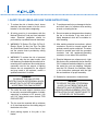
1. SAFETY RULES (READ AND SAVE THESE INSTRUCTIONS)
WARNING
TO REDUCE THE RISK OF FIRE,
ELECTRIC SHOCK OR PERSONAL INJURY,
MOUNT FAN TO OUTLET BOX MARKED
“ACCEPTABLE FOR FAN SUPPORT”
WARNING
TO REDUCE THE RISK OF PERSONAL
INJURY, DO NOT BEND THE BLADE
BRACKETS (ALSO REFERRED TO AS
FLANGES) DURING ASSEMBLY OR AFTER
INSTALLATION. DO NOT INSERT OBJECTS
IN THE PATH OF THE BLADES.

2
60” Motu
™
2. TOOLS AND MATERIALS REQUIRED
• Phillips screw driver
• Blade screw driver
• 11mm wrench
• Step ladder
• Wire cutters
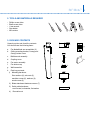
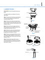
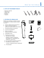
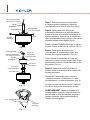
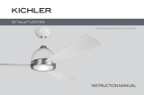
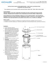
3. PACKAGE CONTENTS
Unpack your fan and check the contents.
You should have the following items:
a. Fan blade/blade arm assemblies (3)
b. Ceiling mounting bracket, Canopy and
Canopy bottom cover
c. Ball/downrod assembly
d. Coupling cover
e. Fan motor assembly
f. Fan bottom cap
g. Wall transmitter
h. Parts bag contents:
1) Mounting hardware:
Star washers (2), wire nuts (3),
machine screws (2), washers (2),
wood screws (2)
2) Blade attachment hardware screws (7)
3) Safety cable hardware:
wood screw, lock washer, at washer
4) Decorative nut
a.
b.
c.
d.
e.
f.
g.
h.
KICHLER
R
-
1
2
3
4

3
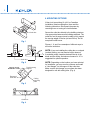
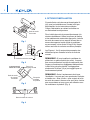
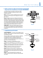
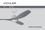
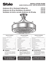
4. MOUNTING OPTIONS
If there isn’t an existing UL (cUL for Canadian
Installation) listed mounting box, then read the
following instructions. Disconnect the power by
removing fuses or turning off circuit breakers.
Secure the outlet box directly to the building structure.
Use appropriate fasteners and building materials. The
outlet box and its support must be able to fully support
the moving weight of the fan (at least 50 lbs). Do not
use plastic outlet boxes.
Figures 1, 2, and 3 are examples of different ways to
mount the outlet box.
NOTE: If you are installing the ceiling fan on a sloped
(vaulted) ceiling, you may need a longer downrod
to maintain proper clearance between the tip of the
blade and the ceiling. A minimum clearance of 12” is
suggested for optimal operation.
NOTE: Depending on the location you have selected
for installation, you may need to purchase and install
a “Joist Hanger” for the support of the outlet box.
Make sure the joist hanger you purchase has been
designed for use with ceiling fans. (Fig. 4)
Outlet box
Provide strong
support
Recessed
outlet box
Ceiling
mounting
plate
Outlet box
Outlet box
ANGLED CEILING
MAXIMUM 30
°
ANGLE
Fig. 2
Fig. 1
Fig. 3
Fig. 4

4
60” Motu
™
Mounting screws
(supplied with
electrical box)
Hook
Ceiling
mounting
bracket
UL Listed
outlet box
120V Wires
Washers
Screws
Plastic Stabilizer
Cross pin
Hanger ball
Set screw
Downrod
Canopy
Canopy cover
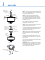
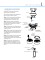
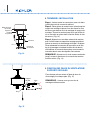
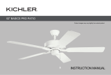
5. HANGING THE FAN
REMEMBER to turn off the power before you
begin.
To properly install your ceiling fan, follow the
steps below.
Step 1. Remove the decorative canopy bottom
cover from the canopy by turning the cover
counterclockwise. (Fig. 5)
Step 2. Remove the ceiling mounting bracket
from the canopy by removing (and save) one of
the two screws. Loosen the remaining screw by
a half turn. (Fig. 5)
Step 3. Pass the 120 volt supply wires from
the ceiling outlet box through the center of the
ceiling mounting bracket. (Fig. 6)
Step 4. Attach the ceiling mounting bracket to
the outlet box using the screws and washers
included with the outlet box. (Fig. 6)
Step 5. Remove and discard the three screws
securing the plastic stabilizer on the bottom of
motor housing. Remove and discard the plastic
stabilizer. (Fig. 7)
Step 6. Remove the hanger ball from the
downrod assembly by loosening the setscrew,
removing the cross pin and turning the ball off
the downrod. (Fig.8)
Fig. 6
Fig. 5
Fig. 7
Fig. 8

5
Registration slot
Check tab
Retaining
clip
Hitch
pin
Set screws
Set screws
Downrod
Coupling
Supply wires
& Safety cable
Hanger ball
Cross pin
Set screw
Downrod
Coupling
Canopy
Canopy cover
Coupling
cover
Supply wires
& Safety cable
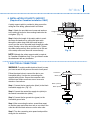
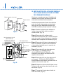
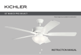
Step 7. Loosen the two setscrews and remove the
hitch pin and retaining clip from the coupling on top
of the motor assembly. (Fig. 9)
Step 8. Carefully route the electrical supply
wires and safety cable exiting the top of the fan
motor assembly through the downrod. Thread the
downrod into the coupling until the hitch pin holes
are aligned. (Fig. 9)
Next, replace the hitch pin and retaining clip.
Tighten both setscrews. (Fig. 9)
Step 9. Slip the coupling cover, canopy cover and
canopy onto the downrod. (Fig. 10)
Thread the hanger ball onto the downrod, insert the
cross pin through the downrod and tighten. Now
tighten the set screw. (Fig. 10)
Step 10. Lift the motor assembly into position and
place the hanger ball into the ceiling mounting
bracket.
Rotate the entire assembly until the “Check Tab”
has dropped into the “Registration Slot” and seats
rmly. (Fig. 11)
The entire motor assembly should not rotate (left or
right) when seated properly.
WARNING: Failure to reattach the cross pin and
seat the “Check Tab” can cause the fan to fall from
the ceiling during operation. Take special care to
make sure this pin is reattached.
Fig. 9
Fig. 10
Fig. 11

6
60” Motu
™
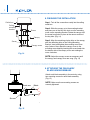
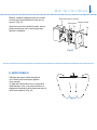
6. INSTALLATION OF SAFETY SUPPORT
(Required for Canadian installation ONLY)
A safety support cable is provided to help prevent the
ceiling fan from falling, please install it as follows.
Step 1. Attach the provided wood screw and washers
to the ceiling joist next to the mounting bracket but do
not tighten. (Fig. 12)
Step 2. Adjust the length of the safety cable to reach
the screw and washers by pulling the extra cable
through the cable clamp until the overall length is
correct, put the end of the cable back through the cable
clamp, forming a loop at the end of the cable. Tighten
the cable clamp securely. Now, put the loop in the end
of the safety cable over the wood screw securely.
NOTE: Although the safety support cable is required
for Canadian installations only. It’s a good idea to make
the attachment with any installation.
7. ELECTRICAL CONNECTIONS
WARNING: To avoid possible electrical shock, be sure
you have turned off the power at the main circuit panel.
Follow the steps below to connect the fan to your
household wiring. Use the wire connecting nuts
supplied with your fan. Secure the connectors with
electrical tape. Make sure there are no loose wire
strands or connections.
Step 1. Connect the fan supply wire (black) to the black
household supply wire. (Fig. 13)
Step 2. Connect the neutral fan supply wire (white) to
the neutral household wire (white).
Step 3. Connect the fan ground wire (green) to the
household ground wire.
Step 4. After connecting the wires, spread them apart
so that the green and white wires are on one side of the
outlet box and the black wires are on the other side.
Step 5. Turn the connecting nuts upward and push the
wiring into the outlet box.
Fig. 12
Fig. 13
Hanger bracket
Safety cable
Attach safety cable
to ceiling joist with
screw and washer
White (neutral)
Outlet box
Black (hot)
Ground
(green)
(Connect to
ground wire on
hanger bracket
if no house
ground wire
exists.)
White (neutral)
Black (motor)

7
Outlet box
Ceiling
mounting
bracket
Canopy
Canopy cover
Screw
Screw
Screws
Blade arm
Blade
8. FINISHING THE INSTALLATION
Step 1. Tuck all the connections neatly into the ceiling
outlet box.
Step 2. Slide the canopy up to the mounting bracket
and place one of the key hole slots over the mounting
screw on the mounting bracket. Rotate the canopy until
the screw head locks in place at the narrow section of
the key hole. (Fig. 14)
Step 3. Align the remaining circular hole on the canopy
with the remaining hole on the Ceiling Mounting
Bracket. Insert and tighten the mounting screw from
step 2 above. Now, attach the canopy cover to the
mounting screw head by inserting the screw heads into
the bottom side of the canopy cover and rotating the
cover clockwise.
NOTE: Adjust the canopy screws as necessary until
the canopy and canopy cover are snug. (Fig. 14)
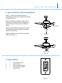
9. ATTACHING THE FAN BLADE/
BLADE ARM ASSEMBLIES
Attach each blade assembly to the motor by using
two mounting screws for each blade assembly.
(Fig. 15)
NOTE: Make sure these mounting screws are
securely tightened.
Fig. 14
Fig. 15

8
60” Motu
™
10. INSTALLING THE BOTTOM CAP
Step 1. Remove and save the two pre-attached
screws on the mounting ring attached to the
motor shaft. (Fig. 16)
Step 2. Push up the bottom cap to the mounting
ring and align the holes on the bottom cap and
mounting ring.
Step 3. Secure the bottom cap by installing the
two screws removed in the rst step and tighten
them.
Step 4. Install the decorative nut by screwing it
into the shaft. (Fig. 17)
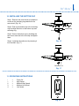
11. OPERATING INSTRUCTIONS
- = Power Off
1 = High Speed
2 = Medium-High Speed
3 = Medium-Low Speed
4 = Low Speed
12
Bottom cap
Screws
Decorative nut
KICHLER
R
-
1
2
3
4
Fig. 17
Fig. 18
Fig. 16

9
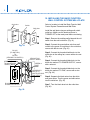
12. INSTALLING THE BASIC FUNCTION
WALL CONTROL SYSTEM WALL PLATE
Select a location to install the Basic Function Wall
Control System Transmitter and Wall Plate.
Install the wall plate using an existing wall switch
outlet box. Make sure the electrical power is
TURNED OFF at the main panel before continuing.
Step 1. Remove the existing wall plate and the old
switch from the wall outlet box. (Fig. 19)
Step 2. Connect the green/yellow wire from wall
control to the green or bare wires in the outlet box,
secure with the wire nut. (Fig. 20)
Step 3. Connect the household white wire to the
white wire to the ceiling fan, secure with a wire nut.
(Fig. 20)
Step 4. Connect the household black wire to the
black wire marked “TO POWER SUPPLY”, secure
with a wire nut.
Step 5. Connect the household black wire to the
black wire marked “TO FAN”, secure with a wire
nut. (Fig. 20)
Step 6. Separate the black wires from the white
and green wires. Turn the green and white wires
into the outlet box. (Fig. 20)
Step 7. Turn the black wires into the outlet box.
(Fig. 20)
Wall plate
Switch
Outlet box
CEILING FAN
SUPPLY WIRES
GREEN/YELLOW
TO HOUSEHOLD
GREEN / BARE
BLACK (TO AC IN L) TO
HOUSEHOLD BLACK
BLACK
(TO MOTOR L)
TO
BLACK
(CEILIING FAN SUPPLY)
GREEN or
BARE
HOUSEHOLD
WHITE TO
WHITE (CEILIING
FAN SUPPLY)
HOUSEHOLD
WIRING
KICHLER
R
-
1
2
3
4
Fig. 19
Fig. 20

10
60” Motu
™
Step 8. Install the wall plate on the existing wall
outlet box using the screws provided. (Fig. 21)
After installing the wall anchors, attach the wall
plate with the mounting screws to nish the
installation.
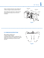
13. OPERATING INSTRUCTIONS
Warm weather operation only:
Forward (counter clockwise)
A downward airow creates a cooling effect. This
allows you to set your air conditioner on a warmer
setting without affecting your general comfort.
(Fig. 22)
Screws
Outlet box
Screws
Wall plate
Switch
KICHLER
R
-
1
2
3
4
Fig. 21
Fig. 22

11
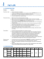
14. TROUBLESHOOTING
Problem
Fan will not start.
Fan sounds noisy.
Fan wobbles.
Remote control
malfunction.
Solution
1. Check circuit fuses or breakers.
2. Check all electrical connections to insure proper contact. CAUTION: Make sure the
main power is OFF when checking any electrical connection.
3. Make sure the transmitter batteries are installed properly. Positive (+) side facing out.
4. Insure the batteries have a good charge.
1. Make sure all motor housing screws are snug.
2. Make sure the screws that attach the fan blade brackets to the motor are tight.
3. Make sure wire nut connections are not rubbing against each other or the interior wall
of the switch housing. CAUTION: Make sure main power is off.
4. Allow a 24-hour “breaking-in period. Most noise associated with a new fan disappears
during this time.
5. If using an optional light kit, make sure the screws securing the glassware are tight.
Make sure the light bulbs are not touching any other component.
6. Do not connect this fan to wall mounted variable speed control(s). They are not
compatible with ceiling fan motors or remote controls.
7. Make sure the upper canopy is a short distance from the ceiling. It should not touch
the ceiling.
1. Check that all blade and blade arm screws are secure.
2. Most fan wobbling problems are caused when blade levels are unequal. Check this
level by selecting a point on the ceiling above the tip of one of the blades. Measure
this distance. Rotate the fan until the next blade is positioned for measurement.
Repeat for each blade. The distance deviation should be equal within 1/8”.
3. Use the enclosed Blade Balancing Kit if the blade wobble is still noticeable.
4. If the blade wobble is still noticeable, interchanging two adjacent (side by side) blades
can redistribute the weight and possibly result in smoother operation.
1. Ceiling fans with remote control systems CAN NOT be operated in conjunction with
any other control system EXCEPT a basic On/Off wall switch, if desired.
2. Make sure the frequency dip switches in the transmitter and receiver have identical
settings.
3. Make sure the Black Antenna on the receiver is NOT tangled with any other electrical
wires and is extended around the inside of the ceiling canopy.
18. SPECIFICATIONS
Fan size Speed Volts Amps Watts RPM CFM CFM/W N.W. G.W. C.F.
60”
High
120
0.84 99.5 245 11891 120
10.9
kgs
12.5
kgs
2.43’
Medium-
High
0.57 44.7 155 7129 160
Medium-
Low
0.38 19.7 85 4217 214
Low 0.26 8.6 55 1828 212
These are approximate measurements. They do not include data for any lamps or xtures attached to the ceiling fan.

Kichler
®
Lighting
7711 East Pleasant Valley Road
P.O. Box 318010
Cleveland, Ohio 44131-8010
Customer Service
866.558.5706
8:30 AM to 5:00 PM EST,
Monday - Friday

Guide d’instructions
Motu
TM
330010
Modèle UL nº 330010xxx
Comprend une commande murale

1
1. Pour réduire les risques d’électrocution,
s’assurer que le courant est coupé au niveau
de la boîte de disjoncteurs ou de fusibles
avant de procéder à l’installation.
2. Tout le câblage doit être conforme aux codes
électriques locaux et au Code électrique
national. L’installation électrique doit être
effectuée par un électricien qualié accrédité.
3. AVERTISSEMENT : Pour réduire les risques
d’incendie ou d’électrocution, n’utilisez ce
ventilateur avec aucun appareil de réglage
de vitesse transistorisé. Utilisez uniquement
la télécommande fournie par le fabricant du
ventilateur de plafond.
4. AVERTISSEMENT : Pour réduire les risques
de blessures, n’utilisez que les deux vis en
acier (et rondelles de blocage) fournies avec
la boîte de sortie de courant pour l’installation
de la boîte de sortie de courant. La plupart
des boîtes de sortie de courant utilisées
normalement pour le support de luminaires
ne sont pas capables de supporter un
ventilateur et ont besoin d’être remplacées;
veuillez consulter un électricien qualié en
cas de doute.
5. La boîte de sortie de courant et la structure
doivent être solidement xées et capables
de supporter un minimum de 23 kg (50 lb)
de façon sûre. Utilisez uniquement des
boîtes de sortie de courant homologuées
CUL, conçues « POUR SUPPORTER UN
VENTILATEUR ».
6. Le ventilateur doit être installé avec une
distance minimale de 3,05 m (10 pi) entre le
bord de fuite des pales et le sol.
7. Ne placez pas d’objets dans la trajectoire
des pales.
8. Pour éviter les blessures ou éviter
d’endommager le ventilateur ou d’autres
objets, faites preuve de prudence en
travaillant près du ventilateur ou en le
nettoyant.
9. N'utilisez ni eau ni détergents pour nettoyer
le ventilateur ou les pales du ventilateur. Un
chiffon à poussière ou un linge légèrement
humide conviennent en général pour le
nettoyage.
10. Après avoir effectué les branchements
électriques, retournez les conducteurs épissés
vers le haut et insérez-les soigneusement dans
la boîte de sortie de courant. Les ls doivent
être écartés de façon à ce que le conducteur
mis à la terre et le conducteur de mise à la
terre de l’équipement soient du même côté de
la boîte de sortie de courant.
11. Les schémas électriques sont fournis à titre
indicatif seulement. Les luminaires qui ne
sont pas compris avec le ventilateur doivent
être homologués CUL et porter une mention
spéciant qu’ils peuvent être utilisés avec ce
type de ventilateur. Les interrupteurs doivent
être homologués CUL pour usage général.
Consultez les instructions fournies avec
les luminaires et les interrupteurs pour un
assemblage approprié.
12. Convient à une utilisation commerciale ou
industrielle.
1. CONSIGNES DE SÉCURITÉ (LISEZ ET CONSERVEZ CES INSTRUCTIONS)
AVERTISSEMENT
POUR RÉDUIRE LES RISQUES D’INCENDIE,
D’ÉLECTROCUTION OU DE BLESSURE,
INSTALLEZ LE VENTILATEUR SUR UNE
BOÎTE DE SORTIE DE COURANT PORTANT
LA MENTION « CAPABLE DE SUPPORTER
UN VENTILATEUR »
AVERTISSEMENT
POUR RÉDUIRE LES RISQUES DE
BLESSURE, NE PLIEZ PAS LES SUPPORTS
DE PALE (AUSSI APPELÉS BRIDES)
PENDANT L’ASSEMBLAGE OU APRÈS
L’INSTALLATION. NE PLACEZ PAS D’OBJETS
DANS LA TRAJECTOIRE DES PALES.

2
Motu
™
de 1,52m (60po)
2. OUTILS ET ÉQUIPEMENT REQUIS
• Tournevis cruciforme
• Tournevis plat
• Clé de 11 mm
• Escabeau
• Coupe-ls
3. CONTENU DE L’EMBALLAGE
Déballez votre ventilateur et vériez le contenu
de l'emballage. Les articles suivants devraient
s’y trouver :
a. Pale de ventilateur/supports de pales (3)
b. Support de montage au plafond,
monture et couvercle inférieur de la monture
c. Ensemble boule/tige de suspension
d. Couvercle d’accouplement
e. Moteur du ventilateur
f. Capuchon inférieur du ventilateur
g. Transmetteur mural
h. Contenu du sac de pièces :
1) Quincaillerie de montage :
Rondelles en étoile (2), capuchons
de connexion (3), vis mécaniques (2),
rondelles (2), vis à bois (2)
2) Vis de quincaillerie de xation des pales (7)
3) Quincaillerie pour câble de sécurité :
vis à bois, rondelle de blocage, rondelle plate
4) Écrou décoratif
a.
b.
c.
d.
e.
f.
g.
h.
KICHLER
R
-
1
2
3
4

3
4. OPTIONS D’INSTALLATION
Si une boîte de sortie de courant homologuée UL
(cUL pour les installations au Canada) n’est pas
déjà installée, lire les instructions suivantes.
Couper l’alimentation en retirant les fusibles ou
en déclenchant les disjoncteurs.
Fixer la boîte de sortie de courant directement à la
structure du bâtiment. Utiliser les pièces de xation
et les matériaux de construction appropriés. La boîte
de sortie de courant et son support doivent être en
mesure de supporter le plein poids du ventilateur
en mouvement, soit au moins 23 kg (50 lb). Ne pas
utiliser une boîte de sortie de courant en plastique.
Les Figures 1, 2 et 3 montrent des exemples des
différentes façons d’installer la boîte de sortie de
courant.
REMARQUE : Si vous installez le ventilateur de
plafond sur un plafond incliné (en voûte), il se peut
que vous ayez besoin d’une tige de suspension plus
longue pour maintenir un dégagement adéquat entre
le bout de la pale et le plafond. Un dégagement
minimum de 30,48 cm (12 po) est suggéré pour un
fonctionnement optimal.
REMARQUE : Selon l’emplacement choisi pour
l’installation, il se peut que vous ayez besoin d’acheter
et installer un « étrier à solive » pour soutenir la boîte
de sortie de courant. Assurez-vous que l’étrier à solive
que vous achetez est conçu pour une utilisation avec
les ventilateurs de plafond. (Fig. 4)
Fournir un
support robuste
Boîte de sortie
de courant
encastrée
Plaque de
montage
au plafond
Boîte de sortie de courant
Boîte de sortie
de courant
Boîte de sortie de courant
PLAFOND INCLINÉ
ANGLE DE 30° MAX
Fig. 2
Fig. 1
Fig. 3
Fig. 4

4
Motu
™
de 1,52m (60po)
Monture
Vis de montage
(fournies avec
la boîte électrique)
Crochet
Support
de montage
au plafond
Boîte de sortie
de courant
homologuée UL
Fils de 120 volts
Rondelles
Couvercle
de monture
Stabilisateur
en plastique
Vis
Contre-goupille
Boule de
suspension
Vis de
pression
Tige de suspension
5. SUSPENSION DU VENTILATEUR
N’OUBLIEZ PAS de couper l’alimentation
électrique avant de commencer.
Pour installer correctement votre ventilateur de
plafond, suivez les étapes suivantes.
Étape 1. Retirez le couvercle décoratif inférieur
de la monture en le tournant dans le sens
inverse des aiguilles d’une montre. (Fig. 5)
Étape 2. Retirez le support de montage au
plafond de la monture en retirant (et conservant)
l’une des deux vis. Desserrez la vis restante
d’un demi tour. (Fig. 5)
Étape 3. Faites passer les ls d’alimentation de
120 volts par le centre du support de montage
au plafond. (Fig. 6)
Étape 4. Fixez le support de montage au plafond
sur la boîte de sortie de courant à l’aide des vis
et rondelles fournies avec la boîte de sortie de
courant. (Fig. 6)
Étape 5. Retirez et jetez les trois vis qui xaient
le stabilisateur en plastique au dessous du
boîtier du moteur. Retirez et jetez le stabilisateur
en plastique. (Fig. 7)
Étape 6. Retirez la boule de suspension de
la tige de suspension en desserrant la vis de
pression, retirant la contre-goupille et tournant
la boule pour la retirer de la tige de suspension.
(Fig. 8)
Fig. 6
Fig. 5
Fig. 7
Fig. 8

5
Les fils d'alimentation
et le câble de sécurité
Les fils d'alimentation
et le câble de sécurité
Boule de
suspension
Goupille
d’attelage
Vis de pression
Tige de
suspension
Tige de
suspension
Vis de pression
Accouplement
Agrafe
Contre-goupille
Monture
Vis de pression
Couvercle
de monture
Accouplement
Couvercle
d’accouplement
Fente d’enregistrement
Languette
antiretour
Étape 7. Desserrez les deux vis de pression
et retirez la goupille d’attelage et l’agrafe de
l’accouplement sur le dessus du moteur. (Fig. 9)
Étape 8. Faites passer avec soin les ls
d’alimentation électrique et le câble de sécurité
sortant du dessus du moteur du ventilateur par la
tige de suspension. Vissez la tige de suspension
dans l’accouplement jusqu’à ce que les trous de la
goupille d’attelage soient alignés. (Fig. 9)
Ensuite, remettez la goupille d’attelage et l’agrafe
en place. Serrez les deux vis de pression. (Fig. 9)
Étape 9. Faites glisser le couvercle de
l’accouplement, le couvercle de monture et la
monture sur la tige de suspension. (Fig. 10)
Vissez la boule de suspension sur la tige de
suspension, insérez la contre-goupille dans la tige
de suspension et serrez. Serrez maintenant la vis
de pression. (Fig. 10)
Étape 10. Soulevez le moteur en position et
placez la boule de suspension dans le support de
montage au plafond.
Tournez tout l’assemblage jusqu’à ce que la
« languette antiretour » tombe dans la « fente
d’enregistrement » et repose fermement. (Fig. 11)
Le moteur complet ne doit pas tourner (à gauche
ou à droite) lorsqu’il est correctement en place.
AVERTISSEMENT : Manquer de rattacher la
contre-goupille et placer la « languette antiretour »
peut entraîner la chute du ventilateur du plafond
pendant l’utilisation. Veillez particulièrement à
rattacher la contre-goupille.
Fig. 9
Fig. 10
Fig. 11

6
Motu
™
de 1,52m (60po)
6. INSTALLATION DU CÂBLE DE SUPPORT DE SÉCURITÉ
(requis pour les installations au Canada UNIQUEMENT)
Un câble de support de sécurité est fourni pour aider à
empêcher le ventilateur de plafond de tomber; veuillez
l’installer comme suit.
Étape 1. Fixez la vis à bois et rondelles fournies à la solive
de plafond, à côté du support de montage mais ne serrez
pas. (Fig. 12)
Étape 2. Réglez la longueur du câble de sécurité pour lui
permettre d’atteindre la vis et les rondelles en tirant l’excès
de câble par le serre-câble, jusqu’à ce que la longueur totale
soit correcte, remettez l’extrémité du câble dans le serre-câble
en formant une boucle à l’extrémité du câble. Serrez bien
le serre-câble. Placez maintenant la boucle à l’extrémité du
câble de sécurité fermement par dessus la vis à bois.
REMARQUE : Bien que le câble de support de sécurité
soit requis pour les installations au Canada uniquement, il
est recommandé d’effectuer cette xation avec toutes les
installations.
7. CONNEXIONS ÉLECTRIQUES
AVERTISSEMENT : Pour éviter toute possibilité de choc
électrique, veillez à couper le courant au niveau du tableau
de distribution principal.
Suivez les étapes ci-dessous pour brancher le ventilateur
au câblage de la maison. Utilisez les capuchons de
connexion fournis avec le ventilateur. Sécurisez ces
connexions avec du ruban isolant. Assurez-vous qu’il n’y a
aucun l ou connexion desserré(e).
Étape 1. Connectez le l d’alimentation (noir) du
ventilateur au l d’alimentation noir de la maison. (Fig. 13)
Étape 2. Connectez le l d’alimentation neutre (blanc) du
ventilateur au l d’alimentation neutre (blanc) de la maison.
Étape 3. Connectez le l de mise à la terre (vert) du
ventilateur au l de mise à la terre de la maison.
Étape 4. Après avoir connecté les ls, séparez-les de
façon à ce que les ls verts et blancs soient d’un côté de
la boîte de sortie de courant et que les ls noirs soient de
l’autre côté.
Étape 5. Tournez les capuchons de connexion vers
le haut et poussez les ls à l’intérieur de la boîte de sortie
de courant.
Fig. 12
Fig. 13
Support de
suspension
Câble de sécurité
Fixez le câble de
sécurité à la solive
de plafond avec
une vis et rondelle
Boîte de sortie
de courant
Blanc (neutre)
Blanc (neutre)
Noir (sous tension)
Mis à
la terre
(vert)
(Connectez au
fil de mise à la terre
sur le support de
suspension si aucun
fil de mise à la terre
n’est présent dans
la maison)
Noir (moteur)
La page est en cours de chargement...
La page est en cours de chargement...
La page est en cours de chargement...
La page est en cours de chargement...
La page est en cours de chargement...
La page est en cours de chargement...
-
 1
1
-
 2
2
-
 3
3
-
 4
4
-
 5
5
-
 6
6
-
 7
7
-
 8
8
-
 9
9
-
 10
10
-
 11
11
-
 12
12
-
 13
13
-
 14
14
-
 15
15
-
 16
16
-
 17
17
-
 18
18
-
 19
19
-
 20
20
-
 21
21
-
 22
22
-
 23
23
-
 24
24
-
 25
25
-
 26
26


Kichler Lighting 330010NI Manuel utilisateur
- Catégorie
- Ventilateurs ménagers
- Taper
- Manuel utilisateur
- Ce manuel convient également à
dans d''autres langues
Documents connexes
-
Kichler 330025BSS Manuel utilisateur
-
 Kichler Lighting Jade 300030 Manuel utilisateur
-
-
 Kichler Lighting 300200PN Manuel utilisateur
-
 Kichler Lighting 300270SBK Manuel utilisateur
-
 Kichler Lighting 310360SBK Manuel utilisateur
-
 Kichler Lighting 330015WH Manuel utilisateur
-
Kichler Lighting 330016SNB Manuel utilisateur
-
 Kichler Lighting 330017SNB Manuel utilisateur
-
 Kichler Lighting 16227CBR50 Manuel utilisateur


Autres documents
-
Progress Lighting P250010 Guide d'installation
-
NOMA Landon Indoor Le manuel du propriétaire
-
-
-
-
for Living 5-blade 3-Speed Le manuel du propriétaire
-
 PROGRESS LIGHTNING P250002-143-30 Mode d'emploi
-
Progress Lighting P250000-081 Manuel utilisateur
-
 Stile CF0140 Mode d'emploi
-

