Bosch GCM12SD Manuel utilisateur
- Catégorie
- Scies à onglet
- Taper
- Manuel utilisateur

For English Version Versión en español Version française
See page 2 Ver la página 56 Voir page 110
GCM12SD
IMPORTANT: IMPORTANTE: IMPORTANT :
Read Before Using Leer antes de usar Lire avant usage
1-877-BOSCH99 (1-877-267-2499) www.boschtools.com
Call Toll Free for
Consumer Information
& Service Locations
Llame gratis para
obtener información
para el consumidor y
ubicaciones de servicio
Pour obtenir des informations
et les adresses de nos centres
de service après-vente,
appelez ce numéro gratuit
Operating/Safety Instructions
Instrucciones de funcionamiento y seguridad
Consignes de fonctionnement/sécurité
BM 2610007877 04-10:BM 2610007877 04-10.qxp 4/26/10 8:13 AM Page 1

2;2?.9&.32AF%B92@
3<?2;05A<='<<9@
*<?8?2.
l 22=D<?8.?2.092.;.;1D29996ACluttered
benches and dark areas invite accidents.
l < ;<A <=2?.A2 =<D2? A<<9@ 6; 2E=9<@6C2
.A:<@=52?2@ @B05 .@ 6; A52 =?2@2;02 <3
39.::./92 96>B61@ 4.@2@ <? 1B@A Power
tools create sparks which may ignite the dust or
fumes.
l 22=/F@A.;12?@05691?2;.;1C6@6A<?@.D.F
D5692 <=2?.A6;4 . =<D2? A<<9 Distractions
can cause you to lose control.
l &A<?26192A<<9@<BA<3?2.05<305691?2;.;1
<A52? B;A?.6;21 =2?@<;@ Tools are danger-
ous in the hands of untrained users.
l < ;<A 92.C2 A<<9 ?B;;6;4 B;.AA2;121 AB?;
=<D2?<33Do not leave tool until it comes to a
complete stop.
l ! *#%&#$ $%## with pad
lock, master switches or by removing starter
keys.
920A?60.9&.32AF
l 23<?2 =9B446;4 6; A52 A<<9 /2 02?A.6; A52
<BA92A C<9A.42 @B==9621 6@ 0<:=.A6/92 D6A5
A52C<9A.42:.?821<;A52;.:2=9.A2D6A56;
An outlet voltage incompatible with that
specified on the nameplate can result in serious
hazards and damage to the tool.
l <B/926;@B9.A21 A<<9@ .?2 2>B6==21 D6A5 .
=<9.?6G21 =9B4 <;2 /9.12 6@ D612?A5.; A52
<A52?'56@=9B4D69936A6;.=<9.?6G21<BA92A
<;9F<;2D.F3A52=9B41<2@;<A36A3B99F6;
A52<BA92A?2C2?@2A52=9B436A@A6991<2@;<A
36A 0<;A.0A . >B.963621 2920A?606.; A<
6;@A.99.=<9.?6G21<BA92A<;<A05.;42A52
=9B46; .;F D.FDouble insulation eliminates
the need for the three-wire grounded power
cord and grounded power supply.
l C<61/<1F0<;A.0AD6A54?<B;121@B?3.02@
@B05.@=6=2@?.16.A<?@?.;42@.;1?23?64
2?.A<?@ There is an increased risk of electric
shock if your body is grounded.
l < ;<A 2E=<@2 =<D2? A<<9@ A< ?.6; <? D2A
0<;16A6<;@ Water entering a power tool will
increase the risk of electric shock.
l <;<A./B@2A520<?1"2C2?B@2A520<?1
A< 0.??F A52 A<<9@ <? =B99 A52 =9B4 3?<: .;
<BA92A22=0<?1.D.F3?<:52.A<69@5.?=
2142@ <? :<C6;4 =.?A@ %2=9.02 1.:.421
0<?1@6::216.A29FDamaged cords increase
the risk of electric shock.
l *52;<=2?.A6;4.=<D2?A<<9<BA@612B@2.;
<BA1<<? 2EA2;@6<; 0<?1 :.?821 K*L <?
K*LThese cords are rated for outdoor use and
reduce the risk of electric shock.
$2?@<;.9&.32AF
l &A.F.92?AD.A05D5.AF<B.?21<6;4.;1B@2
0<::<; @2;@2 D52; <=2?.A6;4 . =<D2?
A<<9 A moment of inattention or use of drugs,
alcohol or medication while operating power
tools can be dangerous.
l ?2@@=?<=2?9F<;<AD2.?9<<@209<A56;4
<? 72D29?F <;A.6; 9<;4 5.6? 22= F<B?
5.6?09<A56;4.;149<C2@.D.F3?<::<C6;4
=.?A@Loose clothes, jewelry or long hair can be
caught in moving parts. Roll long sleeves
above elbows. Rubber gloves and non-skid
footwear are recommended when working out-
doors.
l C<61.00612;A.9@A.?A6;42@B?2@D6A056@
K#L/23<?2=9B446;46; Carrying tools with
your finger on the switch or plugging in tools
that have the switch “ON” invites accidents.
l %2:<C2.17B@A6;482F@<?D?2;052@/23<?2
AB?;6;4A52A<<9K#"L A wrench or a key that
is left attached to a rotating part of the tool will
be thrown.
l < ;<A <C2??2.05 822= =?<=2? 3<<A6;4 .;1
/.9.;02.A .99A6:2@ Proper footing and bal-
ance enable better control of the tool in unex-
pected situations.
l < ;<A @A.;1 <; A<<9 <? 6A@ @A.;1 Serious
injury may occur if the tool is tipped or if the cut-
ting tool is accidentally contacted. Do not store
materials on or near the tool such that it is nec-
essary to stand on the tool or its stand to reach
them.
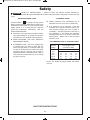
Safety
“READ ALL INSTRUCTIONS” — Failure to follow the SAFETY RULES identified by
BULLET ( ) symbol listed BELOW, and other safety precautions, may result in serious personal
injury.
K&)'&"&'%('#"&L
*%""
!
BM 2610007877 04-10:BM 2610007877 04-10.qxp 4/26/10 8:13 AM Page 2

K&)'&"&'%('#"&L
l (@2 @.32AF 2>B6=:2;A 9D.F@ D2.? @.32AF
4<4492@ Dust mask, safety shoes, hard hat or
hearing protection must be used for appropriate
c
onditions. Everyday eyeglasses only have
impact-resistant lenses, they are NOT safety
glasses.
'<<9(@2.;1.?2
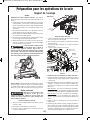
l (@209.:=@<?<A52?=?.0A60.9D.FA<@20B?2
.;1 @B==<?A A52 D<?8=6202 A< . @A./92 =9.A
3<?: Holding the workpiece by hand or against
your body is unstable. It allows for workpiece to
shift, causes binding of the tool and loss of
control.
l < ;<A 3<?02 A<<9 (@2 A52 0<??20A A<<9 3<?
F<B?.==960.A6<; The correct tool will do the job
better and safer at the rate for which it is
designed. Do not use the tool for purpose not
intended - for example, do not use the miter saw
for slicing meats.
l <;<AB@2A<<963@D6A051<2@;<AAB?;6AK#"L
<?K#L Any tool that cannot be controlled with
the switch is dangerous.
l 6@0<;;20A A52 =9B4 3?<: A52 =<D2? @<B?02
/23<?2:.86;4.;F .17B@A:2;A@<?05.;46;4
.002@@<?62@ Such preventive safety measures
reduce the risk of starting the tool accidentally.
l 22=0BAA6;4A<<9@@5.?=.;1092.; Properly
maintained tools, with sharp cutting edges, are
less likely to bind and easier to control. When
mounting saw blades, be certain that the arrow
on the blade matches the direction of the arrow
marked on the tool and that the teeth are also
pointing in the same direction.
l ;@=20A 4B.?1@ /23<?2 B@6;4 . A<<9 22=
4B.?1@ 6; =9.02 5208 :<C6;4 =.?A@ 3<?
/6;16;4<?.;F<A52?0<;16A6<;A5.A:.F.3320A
A52;<?:.9<=2?.A6<;<?@.32AF32.AB?2@<3A52
A<<9 3 1.:.421 5.C2 A<<9 @2?C6021 /23<?2
B@6;4 A52 A<<9 Many accidents are caused by
poorly maintained tools.
l <;<A .9A2? <? :6@B@2 A<<9 Any alteration or
modification is a misuse and may result in seri-
ous personal injury.
l '52 B@2 <3 .;F <A52? .002@@<?62@ ;<A
@=20636216;A56@:.;B.9:.F0?2.A2.5.G.?1
Accessories that may be suitable for one type of
tool may become hazardous when used on an
inappropriate tool.
&2?C602
l '
<<9 @2?C602 :B@A /2 =2?3<?:21 <;9F /F
>B.963621 ?2=.6? =2?@<;;29 Service or mainte-
nance performed by unqualified personnel may
result in misplacing internal wires and compo-
nents which could cause serious hazard.
l *52; @2?C606;4 . A<<9 B@2 <;9F 612;A60.9
?2=9.02:2;A =.?A@ <99<D 6;@A?B0A6<;@ 6;
A52 !.6;A2;.;02 .;1 B/?60.A6<; @20A6<; <3
A56@ :.;B.9 Use of unauthorized parts or
failure to follow maintenance instructions may
create a hazard.
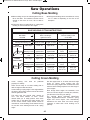
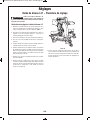
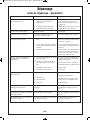
&.32AF%B92@3<?!6A2?&.D@
l To reduce risk of injury, use saw blade rated
3800/min (RPM) or greater.
l (@2 09.:=@ A< @B==<?A D<?8=6202 D52;2C2?
=<@@6/923@B==<?A6;4A52D<?8=6202/F5.;1
F<B :B@A .9D.F@ 822= 5.;1 <BA@612 <3 K"<
.;1L .?2. .@ :.?821 D6A5 . @F:/<9 <; A52
/.@2<;<AB@2A56@@.DA<0BA=6202@A5.A.?2
A<<@:.99A</2@20B?29F09.:=21Your hand, if
placed inside the “No Hands” region, can easily
slip or be pulled into the blade.
l <;<A?2.056;/.08<3A52@.D/9.12/256;1
A52 32;02 D6A5 26A52? 5.;1 A< 5<91 1<D; <?
@B==<?AA52D<?8=6202?2:<C2D<<1@0?.=@<?
3<? .;F <A52? ?2.@<; The proximity of the
spinning saw blade to your hand may not be
obvious and you may be seriously injured.
l "2C2? 0?<@@ F<B? 5.;1 <C2? 6;A2;121 96;2 <3
0BAA6;4 Supporting the workpiece “cross hand-
ed,” i.e., holding the left side of the workpiece with
your right hand, is very dangerous.
l 9D.F@ 16@0<;;20A A52 =<D2? 0<?1 3?<: A52
=<D2?@<B?02/23<?2:.86;4.;F.17B@A:2;A@
<? .AA.056;4 .;F .002@@<?62@ You may
unintentionally start the saw, leading to serious
personal injury.
l !6A2?@.D@.?26;A2;121A<0BAD<<1<?D<<1
9682 =?<1B0A@ A52F 0.;;<A /2 B@21 D6A5
./?.@6C2 0BA<33 D5229@ 3<? 0BAA6;4 32??<B@
:.A2?6.9 @B05 .@ /.?@ ?<1@ @AB1@ 2A0
<D2C2?630BAA6;4:.A2?6.9@9682.9B:6;B:<?
<A52?;<;32??<B@:2A.9@B@2<;9F@.D/9.12@
@=206360.99F ?20<::2;121 3<? ;<;32??<B@
:2A.90BAA6;4Cutting ferrous materi-als causes
excessive sparking and will damage the lower
guard and overload the motor.
Safety
“
READ ALL INSTRUCTIONS” — Failure to follow the SAFETY RULES identified by
BULLET (
l) symbol listed BELOW, and other safety precautions, may result in serious
personal injury.
*%""
!
BM 2610007877 04-10:BM 2610007877 04-10.qxp 4/26/10 8:13 AM Page 3

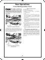
l ;@=20A F<B? D<?8=6202 /23<?2 0BAA6;4 3
D<?8=62026@/<D21<?D.?=2109.:=6AD6A5
A52 <BA@612 /<D21 3.02 A<D.?1 A52 32;02
9D.F@:.8202?A.6;A5.AA52?26@;<4.=/2
A
D22;A52D<?8=620232;02.;1A./92.9<;4
A
5296;2<3A520BA Bent or warped workpieces
can twist or rock and may cause binding on the
spinning saw blade while cutting. Also, make
sure there are no nails or foreign objects in the
workpiece.
l <;<AB@2A52@.DB;A69A52A./926@092.?<3
.99A<<9@D<<1@0?.=@2A02E02=AA52D<?8
=6202 Small debris, loose pieces of wood or
other objects that contact the revolving blade
can be thrown with high speed at the operator.
l <;<A3221D<?8=62026;A<A52/9.12<?0BA
K3?225.;1L 6; .;F D.F *<?8=6202 :B@A /2
@A.A6<;.?F .;1 09.:=21 <? /?.021 /F F<B?
5.;1 Saw must be fed through the workpiece
smoothly and at a rate which will not overload
the saw’s motor.
l BA <;9F <;2 D<?8=6202 .A . A6:2 Multiple
workpieces cannot be adequately clamped or
braced and may bind on the blade or shift dur-
ing cutting.
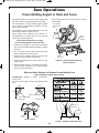
l 2 02?A.6; A52 :6A2? @.D 6@ :<B;A21 <?
=9.021<;. 92C29 36?: D<?8 @B?3.02 /23<?2
B@6;4 A level and firm work surface reduces
the risk of the miter saw becoming unstable.
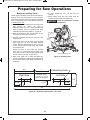
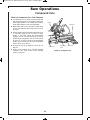
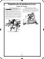
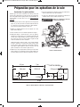
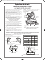
l $9.; F<B? D<?8 $?<C612 .12>B.A2 @B==<?A
.002@@<?62@ @B05 .@ A./92@ @.D 5<?@2@
A./922EA2;@6<;2A03<?D<?8=6202@D612?<?
9<;42? A5.; A52 A./92 A<= @22 =.42 .
Workpieces longer or wider than the miter saw
table can tip if not securely supported. If the
cutoff piece or workpiece tips, it can lift the lower
guard or be thrown by the spinning blade.
l < ;<A B@2 .;<A52? =2?@<; .@ . @B/@A6ABA2
3<? . A./92 2EA2;@6<; <? .@ .116A6<;.9 @B=
=<?A Unstable support for the workpiece can
cause the blade to bind or the workpiece to shift
during the cutting operation, pulling you and the
helper into the spinning blade.
l '52 0BA<33 =6202 :B@A ;<A /2 7.::21
<? =?2@@B?21 /F .;F <A52? :2.;@
.4.6;@A A52 @=6;;6;4 @.D /9.12 If confined,
i.e., using length stops, it could get wedged
against the blade and thrown violently.
l 9D.F@B@2.09.:=<?.36EAB?212@64;21A<
=?<=2?9F @B==<?A ?<B;1 :.A2?6.9 @B05 .@
1<D29?<1@<?AB/6;4Rods have a tendency
to roll while being cut, causing the blade to “bite”
and pull the work with your hand into the blade.
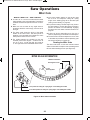
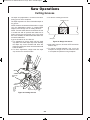
l *52; 0BAA6;4 6??24B9.?9F @5.=21 D<?8
=6202@=9.;F<B?D<?8@<6AD699;<A@96=.;1
=6;05A52/9.12.;1/2A<?;3?<:F<B?5.;1
A piece of molding, for example, must lie flat or
be held by a fixture or jig that will not let it twist,
rock or slip while being cut.
l 2A A52 /9.12 ?2.05 3B99 @=221 /23<?2 0<;
A.0A6;4 A52 D<?8=6202 This will help avoid
thrown workpieces.
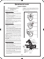
l 3A52D<?8=6202<? /9.12 /20<:2@ 7.::21
<? /<4421 1<D; AB?; :6A2? @.D K#L /F
?292.@6;4 @D6A05 *.6A 3<? .99 :<C6;4 =.?A@
A<@A<=.;1B;=9B4A52:6A2?@.DA52;D<?8
A<3?22A527.::21:.A2?6.9Continued saw-
ing with jammed workpiece could cause loss of
control or damage to miter saw.
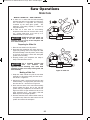
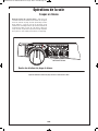
l ?.86;4 .0A6<; <3 A52 @.D 0.B@2@ A52 @.D
52.1 A< 72?8 1<D;D.?1 2 ?2.1F 3<? A56@
?2.0A6<; when making an incomplete cut or
when releasing the switch before the head is
completely in the DOWN position.
l 3A2? 36;6@56;4 A52 0BA ?292.@2 A52 @D6A05
5<91A52@.D.?:1<D;.;1D.6A3<?/9.12A<
@A<= /23<?2 ?2:<C6;4 D<?8 <? 0BA<33 =6202
3 /9.12 1<2@ ;<A @A<= D6A56; 36C2 @20
<;1@B;=9B4A52@.D.;13<99<DA526;@A?B0
A6<;@ 6; A52 '?<B/92@5<<A6;4 @20A6<;
REACHING WITH YOUR HAND UNDER A
COASTING BLADE IS DANGEROUS!
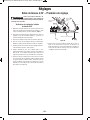
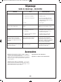
l '52?2 .?2 .116A6<;.9 @.32AF 6;@A?B0A6<;@
3<? =.?A60B9.? <=2?.A6<;@ <3 A52 @.D 6; A52
&.D#=2?.A6<;@@20A6<;%2.1A52?2@A<3A52
:.;B.93<?@.32<=2?.A6<;
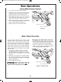
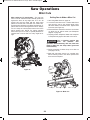
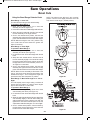
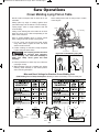
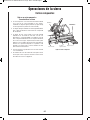
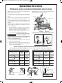
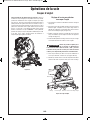
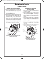
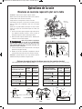
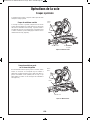
l '52 !& :6A2? @.D 5.@ .; 2EA?2:29F
@:<<A5 .0A6<; .;1 ?2>B6?2@ A52 <=2?.A<? A<
36?:9F4?6=A525.;192/23<?2AB?;6;4K#"LA52
@.D <? @9612.0A6<; 0BAA6;4 36?@A 4?6= A52
@D6A055.;1926;A52($=<@6A6<;.;1=B99<BA
/.08A<A523B99F2EA2;121=<@6A6<;'52/9.12
:B@A 092.? A52 D<?8=6202 !.82 02?A.6; A52
09.:= 1<2@ ;<A 6;A2?32?2 D6A5 A52 4B.?1 .;1
52.1 .@@2:/9F &20<;1 AB?; @.D K#"L .;1
9<D2? A52 @.D A< A52 A./92 '52; $(& @.D
A5?<B45A52D<?8=6202%292.@2A52@D6A05.;1
D.6A 3<? A52 /9.12 A< 0<:=92A29F @A<= /23<?2
?.6@6;4A52 52.1 .@@2:/9F .;1?2:<C6;4 A52
D<?8=6202Never “pullcut,” since blade may climb
the workpiece, causing KICKBACK.
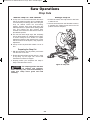
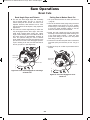
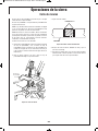
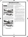
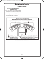
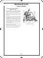
l <? 05<=.0A6<; 0BAA6;4 :<C2 A52 52.1
.@@2:/9F A< A52 ?2.? .@ 3.? .@ 6A D699 4< .;1
2;4.42A52:205.;6@:9<08'52;AB?;A52@.D
K#"L .;1 9<D2? A52 52.1 .@@2:/9F A< :.82
A52 0BA %292.@2 A52 @D6A05 .;1 D.6A 3<? A52
/9.12 A< 0<:=92A29F @A<= /23<?2 ?.6@6;4 A52
52.1.@@2:/9F .;1 ?2:<C6;4 A52 D<?8=6202
Failure to lock the mechanism can cause the blade
to suddenly climb up on the top of the
workpiece and force itself toward you.
Safety
“READ ALL INSTRUCTIONS” — Failure to follow the SAFETY RULES identified by
BULLET (l) symbol listed BELOW, and other safety precautions, may result in serious
personal injury.
*%""
!
K&)'&"&'%('#"&L
BM 2610007877 04-10:BM 2610007877 04-10.qxp 4/26/10 8:13 AM Page 4

l <;<A.99<D3.:696.?6AF4.6;213?<:3?2>B2;A
B
@2 <3 F<B? :6A2? @.D A< /20<:2
0<::<;=9.02 Always remember that a careless
fraction of a second is sufficient to inflict severe
injury.
l THINK SAFETY! SAFETY IS A COMBINATION
OF OPERATOR’S COMMON SENSE,
KNOWLEDGE OF THE SAFETY AND
OPERATING INSTRUCTIONS AND
ALERTNESS AT ALL TIMES WHEN THE MITER
SAW IS BEING USED.
'*%""&&#*" #*
"#("#",#(%'##
'& *%""& % #" , #""&
#%!#'!#%' &',%( &
" $%('#"& '' $$% " ,#(%
#*"%N& !"( ', &%) &
%!"%# &',%( &"#%
&#$%'#"#'&!'%&*
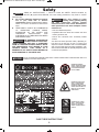
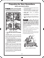
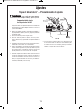
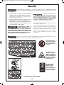
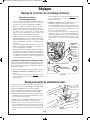
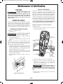
&<:2 1B@A 0?2.A21 /F =<D2?
@
.;16;4@.D6;44?6;16;41?6996;4
.;1 <A52? 0<;@A?B0A6<; .0A6C6A62@ 0<;A.6;@
052:60.9@8;<D;A<0.B@20.;02?/6?A512320A@<?
<A52??2=?<1B0A6C25.?:&<:22E.:=92@<3A52@2
052:60.9@.?2
• Lead from lead-based paints,
• Crystalline silica from bricks and cement and other
masonry products, and
• Arsenic and chromium from chemically treated
lumber.
Your risk from these exposures varies, depending on
how often you do this type of work. To reduce your
exposure to these chemicals: work in a well-ventilated
area, and work with approved safety equipment, such
as those dust masks that are specially designed to filter
out microscopic particles.
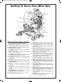
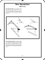
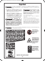
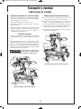
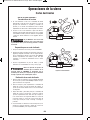
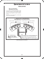
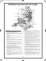
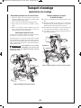
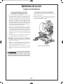
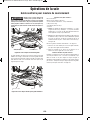
Do Not Carry the
Saw by this handle.
No lleve la sierra
por este mango.
Ne transportez pas la
scie par sa poignée.
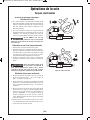
DESIGNATED NO - CARRY
AREA - A DANGER ZONE -
NEVER LIFT OR CARRY
SAW BY THE MAIN SWITCH
HANDLE.
DESIGNATED PINCH POINT
AREA - A DANGER ZONE -
AVOID PLACING HANDS,
FINGERS OR ARMS IN THESE
AREAS. NEVER ATTEMPT TO
MOVE OR LIFT THE SAW IN
THESE AREAS.
DESIGNATED DANGER
ZONES - AVOID POSITIONING
HANDS, FINGERS OR ARMS
IN THE AREA DESIGNATED
BY THIS SYMBOL.
Safety
“READ ALL INSTRUCTIONS” — Failure to follow the SAFETY RULES identified by
BULLET (l) symbol listed BELOW, and other safety precautions, may result in serious
personal injury.
K&)'&"&'%('#"&L
*%""
!
*%""
!
*%""
!
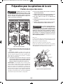
Do not use the Bosch GCM12SD miter saw to cut fiber cement board. The Bosch miter saw is not
intended to cut fiber cement board.
*%""
!
BM 2610007877 04-10:BM 2610007877 04-10.qxp 4/26/10 8:13 AM Page 5

<B/92;@B9.A21'<<9@
D
ouble insulation is a design concept used in
electric power tools which eliminates the need for the
three-wire grounded power cord and grounded power
supply system. It is a recognized and approved
system by Underwriter’s Laboratories, CSA and
Federal OSHA authorities.
l Servicing of a tool with double insulation requires
care and knowledge of the system and should be
performed only by a qualified service technician.
l WHEN SERVICING, USE ONLY IDENTICAL
REPLACEMENT PARTS.
l POLARIZED PLUGS. Your tool is equipped with
a polarized plug (one blade is wider than the
other); this plug will fit in a polarized outlet only
one way. If the plug does not fit fully in the outlet,
reverse the plug. If it still does not fit, contact a
qualified electrician to install the proper outlet. To
reduce the risk of electrical shock, do not change
the plug in any way.
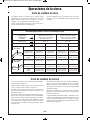
EA2;@6<;<?1@
l Replace damaged cords immediately. Use of
damaged cords can shock, burn or electrocute.
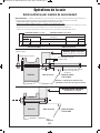
l If an extension cord is necessary, a cord with
adequate size conductors should be used to pre-
vent excessive voltage drop, loss of power or
overheating. The table shows the correct size to
use, depending on cord length and nameplate
amperage rating of tool. If in doubt, use the next
heavier gauge. Always use UL and CSA listed
extension cords.
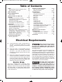
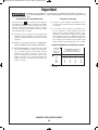
%#!!"&-&#+'"&#"#%&
Tool 120-volt AC Tools
Ampere Cord Length in Feet
Rating Cord Size in AWG
25 50 100 150
3-6 18 16 16 14
6-8 18 16 14 12
8-10 18 16 14 12
10-12 16 16 14 12
12-16 14 12 N/A N/A
NOTE: The smaller the gauge number, the heavier
the cord.
Safety
“READ ALL INSTRUCTIONS” — Failure to follow the SAFETY RULES identified by
BULLET (l) symbol listed BELOW, and other safety precautions, may result in serious personal
injury.
K&)'&"&'%('#"&L
*%""
!
BM 2610007877 04-10:BM 2610007877 04-10.qxp 4/26/10 8:13 AM Page 6

Electrical Requirements
l Connect this saw to a 120V, 15-amp branch cir-
cuit with a 15-amp time delay fuse or circuit
breaker. Using the wrong size fuse can damage
the motor.
l Fuses may “blow” or circuit breakers may trip
frequently if motor is overloaded. Overloading
can occur if you feed the blade into the
workpiece too rapidly or start and stop too often
in a short time.
l Most motor troubles may be traced to loose or
incorrect connections, overload or low voltage
(such as small size wire in the supply circuit or
overly long supply circuit wire). Always check
the connections, the load and the supply circuit
whenever motor does not work well.
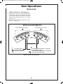
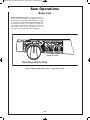
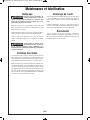
920A?60?.82
Your saw is equipped with an automatic electric
brake which is designed to stop the blade from
spinning in about five (5) seconds after you release
the trigger switch. It is useful when making certain
cuts in wood where a coasting blade would result in
a wide, imprecise cut.
*52;2920A?60.9=<D2?6@9<@A1B2
A< /9<D; 3B@2 <? <A52? 0.B@2@
A52 :<A<? D699 4?.1B.99F @9<D 1<D; .;1 A52
/?.86;4.0A6<;6@6;6A6.A21#" ,/FA52?292.@2<3
A52A?6442?@D6A05
The electric blade brake of your miter saw has been
designed for highest degree of reliability, but
unexpected circumstances such as contamination on
the commutator and brushes or failure of motor’s
components can cause the brake not to activate. If
this condition occurs, turn the saw “ON” and “OFF”
four to five times without contacting the workpiece. If
the tool operates but the brake does not consistently
stop the blade in about five seconds, DO NOT use
saw and have it serviced immediately.
'52 /?.82 .0A6<; <3 A56@ @.D 6@
;<A6;A2;121.@.@.32AF32.AB?2
%2:2:/2? A< 92A A52 @.D /9.12 0<:2 A< .
0<:=92A2@A<= /23<?2 ?.6@6;4A52/9.12 3?<: A52
D<?8=6202@.9D.F@A524B.?1@F@A2:6@F<B?
/2@A =?<A20A6<; .4.6;@A B;6;A2;A6<;.9 0<;A.0A
D6A5.@=6;;6;4@.D/9.12")%D2142<=2;
<?1232.AA5209<@6;4.0A6<;<3A529<D2?4B.?1
*%""
!
*%""
!
&.32AF . . . . . . . . . . . . . . . . . . . . . . . . . . . . . . . . . 2-6
General Safety Rules for Benchtop Tools . . . . 2-3
Safety Rules for Miter Saws . . . . . . . . . . . . . . 3-6
'./92<3<;A2;A@ . . . . . . . . . . . . . . . . . . . . . . . . . 7
920A?60.9%2>B6?2:2;A@ . . . . . . . . . . . . . . . . . . . 7
Electric Brake . . . . . . . . . . . . . . . . . . . . . . . . . . . 7
2AA6;4A<;<D,<B?!6A2?&.D . . . . . . . . . . . 8-9
@@2:/9F . . . . . . . . . . . . . . . . . . . . . . . . . . . . 10-16
Unpacking and Checking Contents . . . . . . . . . 10
Tools Needed for Assembly and Alignment . . . 11
Attaching Loose Parts . . . . . . . . . . . . . . . . . . . 12
Removing and Installing Blades . . . . . . . . . 13-14
Assembling Dust Collection System . . . . . . 15-16
17B@A:2;A@. . . . . . . . . . . . . . . . . . . . . . . . . . 17-25
Using the Head Assembly Lock Pin . . . . . . . . . 17
Using the Glide Movement Controller . . . . . . . 17
Using the Mechanism Lock Lever . . . . . . . . . . 18
Depth of Cut Adjustment . . . . . . . . . . . . . . . . . 19
Miter Detent System – Adjustment Procedure . . 20
0° Bevel Stop – Adjustment Procedure . . . 21-22
45° Bevel Stop – Adjustment Procedure . . 23-24
Adjusting Bevel Lock Tension. . . . . . . . . . . . . . 25
Adjusting Front Stabilizing Bolt. . . . . . . . . . . . . 25
'?.;@=<?A6;4.;1!<B;A6;4 . . . . . . . . . . . . . 26-27
Mounting Applications. . . . . . . . . . . . . . . . . . . . 27
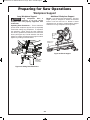
$?2=.?6;43<?&.D#=2?.A6<;@ . . . . . . . . . . . 28-31
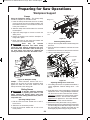
Body and Hand Positions . . . . . . . . . . . . . . . . . 28
Workpiece Support . . . . . . . . . . . . . . . . . . . 29-30
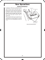
&.D#=2?.A6<;@ . . . . . . . . . . . . . . . . . . . . . . . 32-50
Switch Activation. . . . . . . . . . . . . . . . . . . . . . . . 32
Using Miter Detent System. . . . . . . . . . . . . . . . 33
M
iter Detent Override . . . . . . . . . . . . . . . . . . . . 33
Chop Cuts. . . . . . . . . . . . . . . . . . . . . . . . . . . . . 34
Slide Cuts . . . . . . . . . . . . . . . . . . . . . . . . . . . . . 35
Miter Cuts . . . . . . . . . . . . . . . . . . . . . . . . . . 36-38
Bevel Cuts . . . . . . . . . . . . . . . . . . . . . . . . . . 39-42
Compound Cuts . . . . . . . . . . . . . . . . . . . . . . . . 43
Cutting Grooves . . . . . . . . . . . . . . . . . . . . . . . . 44
Cutting Base Molding . . . . . . . . . . . . . . . . . . . . 45
Cutting Crown Molding . . . . . . . . . . . . . . . . . . . 45
Crown Molding Angled to Table and Fence . . . 46
Crown Molding Lying Flat on Table . . . . . . . . . 47
Crown Molding Auxiliary Fence. . . . . . . . . . 48-49
Special Cuts . . . . . . . . . . . . . . . . . . . . . . . . . . . 50
!.6;A2;.;02.;1 B/?60.A6<; . . . . . . . . . . . .51-52
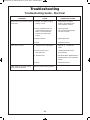
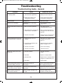
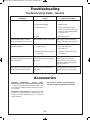
'?<B/92@5<<A6;4 . . . . . . . . . . . . . . . . . . . . . . 53-55
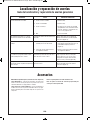
Troubleshooting Guide – Electrical. . . . . . . . . . 53
Troubleshooting Guide – General . . . . . . . . 54-55
002@@<?62@ . . . . . . . . . . . . . . . . . . . . . . . . . . . . 55
Table of Contents
BM 2610007877 04-10:BM 2610007877 04-10.qxp 4/26/10 8:13 AM Page 7

'< .C<61 6;7B?F 3?<: .00612;A.9
@A.?A6;4?2:<C2=9B43?<:=<D2?
@<B?02<BA92A/23<?2:.86;4.;F.17B@A:2;A@
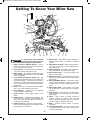
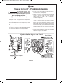
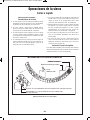
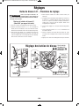
&D6A05 <08# %292.@2 BAA<;@ – One of
these two buttons must be pressed before the
power switch can be pressed.
$<D2?&D6A05 – The power switch used with the
“Lock-OFF” button energizes the unit.
!.6;.;192 – This handle contains the power
switch. Pulling this handle down lowers the blade
into the workpiece.
<D2? 9.12 B.?1 <D2? B.?1 6= – The
lower blade guard helps protect your hands from
the spinning blade. It retracts as the blade is
lowered. Lip can be used to raise the lower guard
in the event that the guard becomes jammed on
a workpiece.
9.12 – Use only 12" (308 mm) diameter blades
with 1" (25.4 mm) diameter arbor holes.
56= 23920A<? – Deflects cut-off workpieces
from entering the upper guard.
(==2? B.?1 – Covers upper portion of the
blade.
&9616;4 2;02 – Supports the workpiece. The
fence has a cast-in scale to make repetitive cuts
easy. The fence also has holes to secure an
auxiliary fence if desired.
&A.A6<;.?F2;02 – Stationary fence is bolted
to the base and will support the workpiece when
the sliding fence is removed.
2?3 ;@2?A@ – Kerf inserts can be adjusted to
different blade widths to minimize workpiece
tear-out.
!6A2?2A2;A#C2??612 – Allows detent action to
be locked out, allowing for micro-adjustments to
any miter angle.
!6A2? <08;</ – The miter lock knob locks the
miter saw table at any desired miter angle.
!6A2? 2A2;A 2C2? – The lever releases the
table from the detent.
2C29 <08 2C2? – The front-positioned bevel
lock lever locks the head assembly at the desired
bevel angle.
!6A2?&0.92!6A2?$<6;A2? – The pointer rotates
with the table and blade. It points to the miter
scale to indicate the angle setting before a cut is
made.
!6A2? 2A2;A $9.A2 – The position of the plate
can be adjusted to set the accuracy of its detent
locations.
!6A2?2A2;A@ – There are ten (10) miter detent
slots for fast and accurate miter cuts of common
miter angles.
'./92 – Sits in base, provides workpiece
support, rotates for desired miter cuts and
rotates the head assembly. The front extended
part of the table is called the miter arm.
.@2 – Provides working surface to support
workpiece.
'<<9!<B;A6;4$.1@ – The four corners of the
saw provide areas to clamp, bolt or nail the saw
to a flat work surface.
*%""
!
Getting To Know Your Miter Saw
1
1
4
5
6
2
3
3
1
8
9
10
11
15
13
12
14
18
19
20
21
22
17
16
8
23
29
28
30
9
24
27
25
26
7
BM 2610007877 04-10:BM 2610007877 04-10.qxp 4/26/10 8:13 AM Page 8

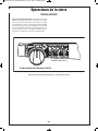
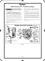
Getting To Know Your Miter Saw
"#''<C62D6A2:@A5?<B45@22=.42
.@2 EA2;@6<; 9.:=6;4 2C2?@ – Lock the
base extensions at the desired positions.
&9616;4 .@2 EA2;@6<;@ – Provide extra work
support. Useful when cutting long workpieces.
%B//2?23920A<? – Attaches to bottom of chute.
Deflects dust into the chute.
B@A5BA2 – Directs sawdust up and through the
elbow and to the bag.
9/<D – Connects the dust chute to the dust bag.
Can be rotated to direct dust.
B@A.4 – Has a zipper at the bottom. Bag can
be uncoupled from elbow for emptying.
!205.;6@: <08 2C2? – Holds saw in full back
position for chop cuts or fully extended for
transporting.
6;8;</ – Attaches guard link to the pivot post.
<D2?B.?1 6;8 – Allows for smooth movement
of the lower guard.
9.:= – Use to hold the workpiece to the table
and base – insert into clamp post location
(item 39).
?B@5 .= – Keeps motor brushes in position.
Provides access for inspecting and replacing
brushes.
2=A5&A<=&0?2D – Turn the knob end to adjust
the blade depth for cutting grooves.
2=A5 &A<= $9.A2 – Plate can be swung out to
limit the depth of the blade travel.
$6C<A$<@A – Provides support for the saw head,
dust collection system and other functional parts.
E6.99612!205.;6@: – Allows saw to smoothly
slide in and out. Can be locked in full rear or fully
extended positions.
2C29 &0.92 .;1 $<6;A2?@ – Scale is large and
angled - allows user to easily read bevel angles.
Pointer indicates what the current angle is.
2C29 $<@A – Provides rotating support for all
miter saw parts above the table.
2C29 2A2;A $6; ?<D; !<916;4 &2AA6;4 –
When engaged, it locks the head assembly to the
bevel angle of 33.9° to the left or right.
9.:=$<@A <0.A6<;@ – Two vertical post holes in
the base – provided to insert the clamp (item 30).
!6A2? 2A2;A $9.A2 &0?2D@ – Four screws
accessible through holes in the miter scale. These
screws are loosened when adjusting position of
the detent plate.
2C29%.;42&2920A<?;</ – Allows selection of
3 bevel ranges: “0-45° Left”, “0-45° Right” or “Max.
Bevel Angle to 47°.”
?/<? <08 – Press arbor lock button to keep
blade from rotating when loosening or tightening
arbor bolt during blade removal or installation.
2.1 @@2:/9F <08 $6; – Used to lock the
head assembly in the lower position for
transporting.
9612!<C2:2;A<;A?<992?– Adjusts to regulate
movement of the glide mechanism.
1
34
32
35
36
37
38
39
40
41
43
33
42
7
(not shown)
44
(
not shown)
BM 2610007877 04-10:BM 2610007877 04-10.qxp 4/26/10 8:13 AM Page 9

Assembly
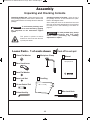
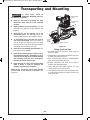
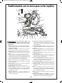
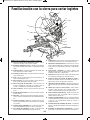
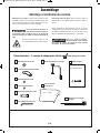
(;=.086;4.;152086;4<;A2;A@
(
;=.086;4A52!6A2?&.D – When removing this tool
from packaging materials, reach down to the two side
carry-handle locations and slowly lift until it clears the
package.
'
<.C<61 @2C2?2=6;056;4 ;2C2?
963A<?:<C2A56@@.D/F4?6==6;4
.;F 0<:=<;2;A <3 A52 :205.;6@: @B==<?A
@F@A2:
This symbol is placed at various
locations on the tool to warn the user
of pinch-point areas.
52086;4<;A2;A@6;$.08.42 – Open the top of
the package and look for the included loose parts.
Refer to the diagram below.
Some small parts such as the bevel lock lever and
miter lock knob require attachment to the tool before
i
t is ready for use – See “Attaching Loose Parts” on
page 12.
'<.C<61 =<@@6/926;7B?F .9D.F@
16@0<;;20A =9B4 3?<: =<D2?
@<B?02 /23<?2 =2?3<?:6;4 .;F .@@2:/9F
.17B@A:2;A@<??2=.6?@
*%""
!
*%""
!
Bevel Lock Lever
6mm Flat Washer
6mm Lock Nut
10 mm Socket Tool
Workpiece Clamp
Manual
Miter Lock Knob
Op e rati ng/S a fety Inst ruct i ons
Loose Parts - 1 of each shown
Check off for each part
Dust Bag
6/4mm Hex Key
10mm Flat Washer
BM 2610007877 04-10:BM 2610007877 04-10.qxp 4/26/10 8:13 AM Page 10

Assembly
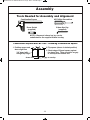
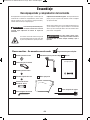
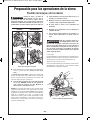
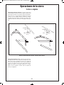
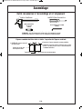
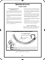
Combination Square Must Be True - Checking Combination Square
1. Position square and
draw a light line
2. Flip square (shown in dotted position)
3. Check edge of flipped square against
the drawn line. There should be no gap
or overlap at the bottom end.
drawn line
3/4" board with
straight top edge
no gap or overlap
Tools Needed for Assembly and Alignment
Combination Square
6/4mm Hex Key
(supplied)
10mm Socket
(supplied)
#2 Phillips Screwdriver
NOTE: A 6mm and a 4mm hex key can be
substituted for the supplied 6/4mm hex key.
BM 2610007877 04-10:BM 2610007877 04-10.qxp 4/26/10 8:13 AM Page 11

Assembly
'< .C<61 =<@@6/92 6;7B?F
1
6@0<;;20A =9B4 3?<: =<D2?
@<B?02 /23<?2 =2?3<?:6;4 .;F .@@2:/9F
.17B@A:2;A@<??2=.6?@
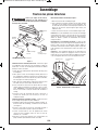
64B?2
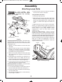
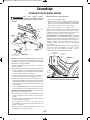
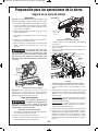
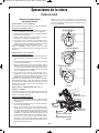
AA.056;4A522C29 <08 2C2? – This miter saw is
packaged with the saw head locked at 0° bevel
angle. The bevel lock lever must be attached before
operating the tool.
1. Slide the 10 mm flat washer over the shaft (area
with flats).
2. Slide the bevel lock lever over the shaft, aligning
the flats on the shaft to the flats on the lever’s
mounting hole. The lever should be horizontal with
the handle to the front (see Figure 1).
3. Slide the 6 mm flat washer over the shaft (area
with screw threads) and against the recessed wall
of the lever.
4. Finger-tighten the 10mm lock nut on the shaft. Use
the 10mm socket tool to tighten the lock nut.
NOTE: The 6/4mm hex key is placed through the
holes in the socket tool to assist in tightening.
5. Lift the bevel lock lever and push back down to
check that the lever is securely in place.
AA.056;4A52!6A2? <08;</ – Locate the miter
lock knob from among the loose parts.
1. Look under the turntable’s front arm above the lock
lever and locate the 10mm hole (see Figure 1).
2. Insert the long shaft of the miter lock knob through
this hole until it stops.
3. Turn the knob clockwise (about 10 full revolutions)
until it is tight or “locked.”
4. Loosen the knob 1/2 turn to unlock it. The table is
now free to be moved on the base.
(@6;4A52!6A2? <08;</ –
1
. Loosen the miter lock knob.
2. While holding the knob in your palm, reach down
with your index or middle finger and pull up the
detent lever. While gripping knob, rotate table left
or right to needed miter angle and release the
lever.
3. Tighten the knob once you are at the correct angle.
NOTE: It is recommended to tighten the miter lock
knob before all cuts. It is required to tighten the knob
before cutting at any angle between detent
engagements or when the miter detent override
system is in use.
&A<?6;4 A52 :: 2E 2F – There is a storage
location on the saw to store the 6/4mm hex key.
Insert the short leg of the hex key through the rubber
grommet as shown. Place the long leg into the tool rest
and press down into the retainer clip (see Figure 2).
NOTE: The 6/4mm hex key is needed to change the
blade and to make tool adjustments. If lost, two
separate hex keys may be substituted: a 4mm hex
key and a 6mm hex key.
64B?22E2F&A<?.42
Miter
Lock Knob
Bevel Lock
Lever
Miter
Detent Lever
Hex Key
10mm Socket Tool
Lock Nut
Shaft
10 mm
Washer
6 mm
Washer
*%""
!
Grommet
Tool Rest
6/4mm
Hex Key
Retainer
Clip
AA.056;4 <<@2$.?A@
BM 2610007877 04-10:BM 2610007877 04-10.qxp 4/26/10 8:13 AM Page 12

Assembly
'< .C<61 =<@@6/92 6;7B?F
1
6@0<;;20A =9B4 3?<: =<D2?
@<B?02 /23<?2 =2?3<?:6;4 .;F .@@2:/9F
.17B@A:2;A@<??2=.6?@
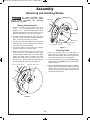
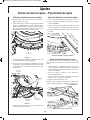
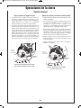
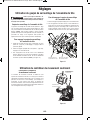
!<C6;4B.?1@@2:/9F
1. Position the saw in the UP position and at 0°
bevel. If in the DOWN position, press down
slightly on the saw head assembly and pull out
the head assembly lock pin (item 43, page 9); then
allow the saw head to come up (see Figure 3).
2. Unscrew the link knob (item 28, page 9) by hand
from the pivot post and allow the link assembly to
hang. The link knob will stay on the link.
3. Loosen front cover plate screw two turns using the
6/4mm hex key. Do not remove screw. A 4mm hex
key may be used as an alternate.
4. Loosen rear plate screw six full turns using the
6/4mm hex key. Do not remove screw.
5. Slide the cover plate down and out from the rear
screw. Rotate the cover plate and lower guard
counterclockwise around the front screw. While
holding the lower guard up against the upper
guard, move the link so its round hole can go over
the rear screw – let go and the lower guard assem -
bly will be held out of the way (see Figure 4).
64B?2
64B?2
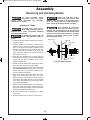
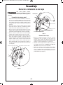
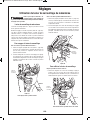
%2:<C6;49.12
1. Press and hold the arbor lock (red button on
opposite side of upper guard – item 42, page 9).
Rotate the blade slowly while pressing the arbor
lock until it fully seats into its lock position.
2. Using the 6/4mm hex key, loosen the blade bolt by
firmly turning it 09<08D6@2. NOTE: This bolt has
left-hand threads.
3. Remove the blade bolt and outer washer. Carefully
grab the blade. Slide the blade away from the inner
washer and off the arbor shaft, then down and
away from the saw. Leave the inner washer on the
arbor shaft (see Figure 5).
Guard Link
Rear Cover Plate Screw
Cover Plate
Blade Bolt
Blade Rotation
Arrow
Front Cover Plate Screw
Knob
Rear Cover Plate Screw
Link
Cover
Plate
*%""
!
%2:<C6;4.;1;@A.996;49.12@
BM 2610007877 04-10:BM 2610007877 04-10.qxp 4/26/10 8:13 AM Page 13

Assembly
'< .C<61 =<@@6/92 6;7B?F
1
6@0<;;20A =9B4 3?<: =<D2?
@<B?02 /23<?2 =2?3<?:6;4 .;F .@@2:/9F
.17B@A:2;A@<??2=.6?@
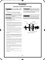
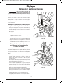
;@A.996;4 9.12
'< .C<61 6;7B?F 1< ;<A B@2 .
/9.12 9.?42? <? @:.992? A5.;
16.:2A2? .;1 .?/<? '52 /9.12N@ :.E6:B:
=9.A2A5608;2@@6@
To reduce risk of injury, use saw
blade rated 3800/min (RPM) or
greater.
1. Follow all “Moving Guard Assembly” and “Remov-
ing Blade” steps.
2. Carefully handle the new blade. Check that the
rotation arrow on the blade matches the rotation
arrow on the lower guard. Slide the blade up and
between the sides of the chip deflector and over
the arbor shaft. Move the blade so its arbor hole
goes around the support ring of the inner washer
(see Figures 4 and 5).
3. Place the outer washer over the arbor shaft and
finger-tighten the blade bolt (counterclockwise).
Check that the blade remained on the inner
washer’s support ring.
4. Rotate the blade slowly while pressing the arbor
lock until it fully seats into its lock position.
5. Using the 6/4mm hex key, firmly tighten the blade
bolt 0<B;A2?09<08D6@2. NOTE: This bolt has left-
hand threads. Do not over tighten. A 6mm hex key
may be used as an alternate.
6. Remove the lower guard link from the rear cover
plate screw. Rotate the lower guard and cover
plate around the front cover plate screw until the
cover plate’s slot slides under the rear cover plate
screw head. Fully tighten both cover plate screws
using the 6/4mm hex key.
7. Place the lower guard link back to the original po-
sition, then firmly finger-tighten the link knob to the
pivot post. It may be necessary to retract the lower
guard while tightening the link knob.
8. Be sure the arbor lock is released so the blade
turns freely.
9. Place the 6/4mm hex key back in storage area.
'645A2; A52 0<C2? =9.A2 @0?2D@
<<@2 0<C2? =9.A2 @0?2D@ :.F
6;A2?32?2 D6A5 .;1 5.;4 B= 9<D2? /9.12 4B.?1
"2C2? B@2 @.D D6A5<BA 0<C2? =9.A2 @20B?29F 6;
=9.02 <D2?4B.?1D699;<A3B;0A6<;=?<=2?9F
3A2? 6;@A.996;4 . ;2D /9.12
:.82 @B?2 A52 /9.12 1<2@ ;<A
6;A2?32?2D6A5A52A./926;@2?A.AH.;1H/2C29
=<@6A6<;@ <D2?A52/9.126;A<A52/9.12@9<A.;1
052083<?.;F0<;A.0AD6A5A52/.@2<?AB?;A./92
@A?B0AB?2 3 A52 /9.12 0<;A.0A@ /.@2 <? A./92
@228.BA5<?6G21@2?C602
64B?29.12.?1D.?2
Outer Washer
I
nner Washer
Blade Bolt
Saw Blade
Arbor Shaft
Support Ring
*%""
!
*%""
!
*%""
!
*%""
!
%2:<C6;4.;1;@A.996;49.12@
*%""
!
BM 2610007877 04-10:BM 2610007877 04-10.qxp 4/26/10 8:13 AM Page 14

Assembly
'< .C<61 =<@@6/92 6;7B?F
1
6@0<;;20A =9B4 3?<: =<D2?
@<B?02 /23<?2 =2?3<?:6;4 .;F .@@2:/9F
.17B@A:2;A@<??2=.6?@
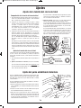
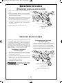
The dust collection system used on this tool is unique
because it is not attached to the upper guard. This
placement provides superior dust collection for the
majority of cuts. When adjusting or removing any dust
collection components, be sure the saw is unplugged.
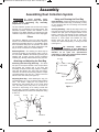
9/<D
The elbow is attached to the top of the dust chute.
NOTE: It is recommended that the elbow is always in
place before operating the tool – it is required to direct
dust and debris away from the operator. The elbow
can be rotated in place. The elbow supports the dust
bag or can be connected to a vacuum cleaner.
%2:<C6;49/<D – For cleaning, the elbow may be
removed by pulling up and twisting until it is free of
the dust chute. Reattach the elbow by pressing and
twisting until it snaps over the chute’s molded-in
retaining ring. Always reattach before using the saw.
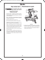
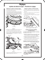
AA.056;4.;117B@A6;4A52B@A.4
AA.056;4.;1%2:<C6;4B@A.4 – The elbow
has pins on the top and bottom of the exit port which
will engage the coupler end of the dust bag
assembly. To attach the dust bag, align the coupler’s
slots with the elbow’s pins, then push and twist it
clockwise. To remove the dust bag, twist the coupler
counterclockwise, then pull off – always leave the
elbow on the dust chute (see Figure 6).
17B@A6;4B@A.4 – After attaching the bag, it is
recommended to do a “dry cut” before cutting with the
saw – this means: unplug the tool, preset it for
intended cut and practice the cut. For some bevel
cuts, the sliding fence may have to be moved or
removed to avoid being cut or making contact with
the dust bag. The bag’s position may also need a
rotating adjustment if it contacts the workpiece during
a slide cut.
64B?2
(@6;4.;192.;6;4A52B@A.4
(@6;4B@A.4 – Attach the clean bag to the elbow.
Adjust the elbow and dust bag, if necessary, so they
d
o not interfere with the tool during the intended
cutting operation.
92.;6;4B@A.4 – After the dust bag is 2/3 to 3/4
full, remove it from the saw. Bring the bag to a proper
container and pull open the zipper located on the
bottom of the bag. Hold the bag by the coupler end
and shake it vigorously until all the dust and debris
fall from it. Close zipper and reattach the bag.
NOTE: Clean the bag at the end of the cutting
session and before transporting or storing the saw
(see Figure 7).
2 2EA?2:29F 0.?23B9 D52;
16@=<@6;4 <3 1B@A !.A2?6.9@ 6;
36;2=.?A60923<?::.F/22E=9<@6C2<;<AA5?<D
@.D1B@A <; .; <=2; 36?2 &=<;A.;2<B@
0<:/B@A6<;6;A6:2:.F?2@B9A3?<:A52:6EAB?2
<3<69<?D.A2?D6A51B@A=.?A6092@
64B?2
Coupler
Zipper
Dust Bag
Dust Chute
Rubber Deflector
Elbow
*%""
!
Coupler
Slot
Pin
Dust Bag
Elbow
Dust Chute
*%""
!
@@2:/96;4B@A<9920A6<;&F@A2:
BM 2610007877 04-10:BM 2610007877 04-10.qxp 4/26/10 8:13 AM Page 15

Assembly
'< .C<61 =<@@6/92 6;7B?F
1
6@0<;;20A =9B4 3?<: =<D2?
@<B?02 /23<?2 =2?3<?:6;4 .;F .@@2:/9F
.17B@A:2;A@<??2=.6?@
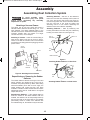
AA.056;4.).0BB:92.;2?
T
he elbow has an exit port which will accept a
standard 35mm diameter vacuum fitting or a 1-1/4"
tube diameter. The 35mm diameter fitting is the
standard size used on the Bosch Airsweep
TM
Vacuum
Cleaners, Models 3931 and 3931A. For larger
vacuum tube sizes, use an adaptor.
AA.056;4A<).0BB: – Insert the vacuum fitting or
tube into the elbow’s exit port as far as it will go.
Check to see that the vacuum hose is free from the
mechanism and cutting path before plugging saw into
power source.
64B?2AA.056;4).0BB:92.;2?
%2=<@6A6<;6;4<?%2:<C6;4A52%B//2?
23920A<?
The rubber deflector extends the range of dust and
debris collection and should be left on the tool for
maximum dust pickup efficiency. When slide cutting
extra-tall materials (more than 2-13/16" high), the
rubber deflector will contact and flex over these
materials. It will also contact and flex when the saw is
pulled back before the cut. It will return to its original
shape after the cut.
%2=<@6A6<;6;423920A<? – If the operator wants to
avoid the contact of the rubber deflector with the
material, the deflector can be temporarily folded up
and over the back of the dust chute. If the operator
permanently wants no contact of the deflector with
the material being cut, the deflector may be removed.
%2:<C6;4 23920A<? – Pull one of the deflector’s
tabs to the front and then sideways until it comes off
one of the dust chute’s side hooks (see Figure 9).
Unhook the opposite side. Then unhook the deflector
f
rom the rear post of the chute by pulling and
stretching until it is free. NOTE: Removing the
deflector lowers dust collection capability.
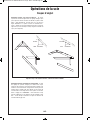
AA.056;4 23920A<? – Start by stretching and
hooking the deflector over the rear post, followed by
hooking over each side hook (see Figure 10).
64B?2
AA.056;4%B//2?23920A<?<;%2.?$<@A
64B?2
AA.056;4%B//2?23920A<?<;&612<<8@
Side Hook
Rear
Post
Side Hook
Rear
Post
Rear of
Dust Chute
Rubber Deflector
Vacuum
Hoses
35 mm
Diameter
1-1/4 inch
Diameter
Elbow
Exit
Port
Dust Chute
*%""
!
@@2:/96;4B@A<9920A6<;&F@A2:
BM 2610007877 04-10:BM 2610007877 04-10.qxp 4/26/10 8:13 AM Page 16

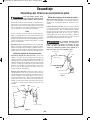
Adjustments
'< .C<61 =<@@6/92 6;7B?F
1
6@0<;;20A =9B4 3?<: =<D2?
@<B?02 /23<?2 =2?3<?:6;4 .;F .@@2:/9F
.17B@A:2;A@<??2=.6?@
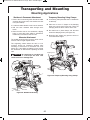
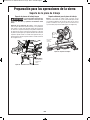
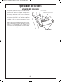
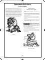
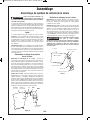
2.1@@2:/9F <08$6;
T
he head assembly lock pin (item 43 - page 9) is
located on the right side of the pivot post (item 34 -
page 9). It is used to hold the saw’s head assembly
in the DOWN position. This position prevents the
head from bouncing up and down during
transportation. This also makes the saw more
compact for lifting and storage. This position is also
required for some calibrating procedures.
'<;4.42A522.1@@2:/9F <08$6;
1. Check that the depth stop plate (item 33 - page 9)
is disengaged, or pressed in to the left position.
2. Grasp the saw’s main handle (item 3 - page 8) and
press down on the head assembly.
3. While pressing the saw head down, push in on the
head assembly lock pin. Release the head
assembly. The head will be locked in the DOWN
position (see Figure 11).
'<6@2;4.42A522.1@@2:/9F
<08$6;
1. Grasp the main handle and press down on the
head assembly.
2. While pressing the head down, pull out the head
a
ssembly lock pin. Release the lock pin, but
maintain your grip on the main handle. Slowly
allow the spring-loaded saw head to come up to
the top of its travel and then release the handle.
64B?2
*%""
!
Depth Stop
Plate
Head Assembly
Lock Pin
(@6;4A522.1@@2:/9F <08$6;
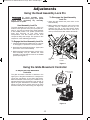
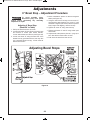
'<17B@AA529612!<C2:2;A
<;A?<992?
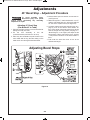
The glide movement controller is attached to the
upper joint of the glide mechanism; it is designed to
control the smoothness of the saw’s glide action.
When assembled at the factory, the controller is not
adjusted; therefore, the movement is very smooth. To
adjust the glide mechanism’s smoothness, slightly
tighten or loosen the two screws at the top by using
the 6/4mm hex key or a 4mm hex key (see Figure 12).
64B?2
6/4mm Hex Key
x 2 Screws
Glide Movement
Controller
(@6;4A529612!<C2:2;A<;A?<992?
BM 2610007877 04-10:BM 2610007877 04-10.qxp 4/26/10 8:13 AM Page 17

Adjustments
'< .C<61 =<@@6/92 6;7B?F
1
6@0<;;20A =9B4 3?<: =<D2?
@<B?02 /23<?2 =2?3<?:6;4 .;F .@@2:/9F
.17B@A:2;A@<??2=.6?@
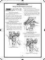
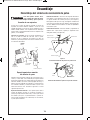
!205.;6@: <08 2C2?
T
he lock lever (item 27 - page 9) is located on the
rear left side of the mechanism.
When engaged, it locks the system (item 35 – page
9) in either the full forward or the full back position
and prevents movement while transporting the saw.
When held in the full back position, the saw is more
compact for lifting and storage. The full back position
is often used while performing chop cuts.
'<;4.42A52 <08 2C2?
*6A5&.D6;A52B99.08$<@6A6<;J
1. Grasp the saw’s main handle (item 3 - page 8)
and push (slide) the head assembly back as far as
it goes. The upper housings will be upright and
closed.
2. Lift the tab on the lock lever to engage its wedge
into the joint area between the two lower
housings. Release the lock lever tab and the main
handle. The head assembly will be locked in the
full back position.
64B?2
'<;4.426;.08$<@6A6<;
*6A5&.D6;A52B99<?D.?1$<@6A6<;J
1. Grasp the main handle (item 3 - page 8) and pull
(
slide) the head assembly toward you as far as it
goes. The mechanism will be fully extended.
2. Lift the tab on the lock lever to engage its wedge
into the joint area between the two lower
housings. Release the lock lever tab and the main
handle. The head assembly will be locked in the
full forward position.
64B?2
'<%292.@2A52 <08 2C2?
?<:.08<?<?D.?1$<@6A6<;@J
1. Grip the tab on the lock lever and press down until
its wedge comes out from between the two lower
housings. Release your grip; the mechanism is
now free to slide forward and back.
64B?2
'<%292.@26;?<;A<?.08$<@6A6<;
Lock
Lever Tab
Lock
Lever Tab
Lock
Lever Tab
*%""
!
(@6;4A52!205.;6@: <08 2C2?
BM 2610007877 04-10:BM 2610007877 04-10.qxp 4/26/10 8:13 AM Page 18

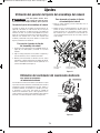
Adjustments
'< .C<61 =<@@6/92 6;7B?F
1
6@0<;;20A =9B4 3?<: =<D2?
@<B?02 /23<?2 =2?3<?:6;4 .;F .@@2:/9F
.17B@A:2;A@<??2=.6?@
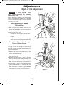
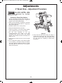
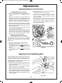
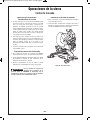
When a new blade is installed, it may be necessary
to check the clearance of the blade to the turntable
structure. The depth stop plate is a feature provided
to allow for (normal) full-depth cuts or non-through
cuts used to cut grooves.
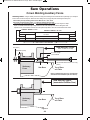
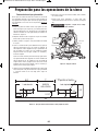
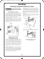
&2AA6;49.122=A53<?"<?:.9
B992=A5BA@
1. When making normal full-depth cuts, push the
depth stop plate in toward the saw head (see
Figure 16). This will allow the depth stop screw to
pass through the hole in the plate.
2. Check for full depth of cut:
- Set table at 0° miter and push saw fully back.
- Pull out head assembly lock pin to the release
position.
- Push down saw head and watch the depth stop
screw pass through the stop plate without any
binding or contact with the plate.
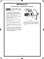
&2AA6;49.122=A53<?"<;'5?<B45
BA@3<?BAA6;4?<<C2@
NOTE: For best results, Bosch recommends the use
of a table saw with an optional dado blade set for
cutting grooves and non-through cuts. In the event
this is not available, the feature described below is a
convenient alternative.
1. Release (pull out) the head asembly lock pin and
allow the saw head to move fully up. Slide saw
head to the full back position.
2. Pull the depth stop plate out away from the saw
head (see Figure 17).
3. Grip the main handle (item 3, page 8) and push
down the saw head while watching the depth stop
screw contact the top surface of the depth stop
plate. The screw will not pass through the hole in
the plate.
4. Turn the knob at the end of the depth stop screw
(while the threaded end is in contact with stop
plate) and watch the bottom of the saw blade
move. This adjustment sets the depth of cut.
See page 44 for “Cutting Grooves” instructions.
64B?2
64B?2
Depth
Stop Screw
Depth Stop
Plate
Depth
Stop Screw
Depth Stop
Plate
Head Assembly
Lock Pin
*%""
!
2=A5<3BA17B@A:2;A
BM 2610007877 04-10:BM 2610007877 04-10.qxp 4/26/10 8:13 AM Page 19

Adjustments
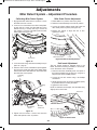
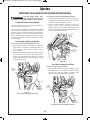
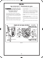
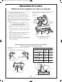
!6A2?2A2;A&F@A2:J17B@A:2;A$?<021B?2
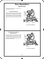
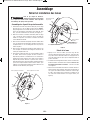
.96/?.A6;4!6A2?2A2;A&F@A2:
1
. Engage the miter detent at the 0° position. Loosen
the miter lock knob 1/2 turn.
2. Look for four round holes in the miter scale plate.
In each hole is a screw. Use the small end of the
6/4mm hex key or a 4mm hex key to loosen all
four screws 1 to 2 turns. This will loosen the miter
detent plate (see Figure 18).
64B?2
3. Lock saw down using the head assembly lock pin
(item 43 – page 9).
4. Hold one side of a 90° combination square against
the fence and rotate the table (and detent plate)
until the side of the saw blade is in full contact with
the other side of the square.
64B?2
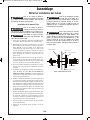
5. Tighten all four screws – loosen and reset the
miter scale pointer to the “0” position.
!6A2?&0.92$<6;A2?17B@A:2;A
1
. Rotate table to 0° position and lock in place.
2. Raise the head assembly to the full UP position.
3. Loosen the pointer adjust screw that holds the
miter scale pointer in place (see Figure 20).
4. Position the pointer to align with the 0° line.
Tighten the screw.
64B?2!6A2?&0.9217B@A:2;A
2?3;@2?A17B@A:2;A
The kerf inserts should be adjusted close to the
blade, but without touching the blade, to avoid tear-
out on the bottom of the workpiece.
1. Hold the saw head assembly down and push in
the head assembly lock pin (item 43 – page 9) to
keep the saw in the DOWN position.
2. Loosen the six kerf screws using a #2 Phillips
screwdriver.
3. Adjust the kerf inserts as close to the blade (teeth)
as possible without touching the blade.
4. Tighten the kerf screws.
NOTE: At extreme bevel angles, the saw blade may
slightly cut into kerf insert.
64B?22?3;@2?A@
Kerf Inserts
Kerf Screws
Pointer Adjust Screw
Miter Scale Pointer
0° Line
Contacting
Fence
Contacting
Blade
Combination
Square
Set Miter
Detent at 0°
Detent Plate
Screws
BM 2610007877 04-10:BM 2610007877 04-10.qxp 4/26/10 8:13 AM Page 20
La page est en cours de chargement...
La page est en cours de chargement...
La page est en cours de chargement...
La page est en cours de chargement...
La page est en cours de chargement...
La page est en cours de chargement...
La page est en cours de chargement...
La page est en cours de chargement...
La page est en cours de chargement...
La page est en cours de chargement...
La page est en cours de chargement...
La page est en cours de chargement...
La page est en cours de chargement...
La page est en cours de chargement...
La page est en cours de chargement...
La page est en cours de chargement...
La page est en cours de chargement...
La page est en cours de chargement...
La page est en cours de chargement...
La page est en cours de chargement...
La page est en cours de chargement...
La page est en cours de chargement...
La page est en cours de chargement...
La page est en cours de chargement...
La page est en cours de chargement...
La page est en cours de chargement...
La page est en cours de chargement...
La page est en cours de chargement...
La page est en cours de chargement...
La page est en cours de chargement...
La page est en cours de chargement...
La page est en cours de chargement...
La page est en cours de chargement...
La page est en cours de chargement...
La page est en cours de chargement...
La page est en cours de chargement...
La page est en cours de chargement...
La page est en cours de chargement...
La page est en cours de chargement...
La page est en cours de chargement...
La page est en cours de chargement...
La page est en cours de chargement...
La page est en cours de chargement...
La page est en cours de chargement...
La page est en cours de chargement...
La page est en cours de chargement...
La page est en cours de chargement...
La page est en cours de chargement...
La page est en cours de chargement...
La page est en cours de chargement...
La page est en cours de chargement...
La page est en cours de chargement...
La page est en cours de chargement...
La page est en cours de chargement...
La page est en cours de chargement...
La page est en cours de chargement...
La page est en cours de chargement...
La page est en cours de chargement...
La page est en cours de chargement...
La page est en cours de chargement...
La page est en cours de chargement...
La page est en cours de chargement...
La page est en cours de chargement...
La page est en cours de chargement...
La page est en cours de chargement...
La page est en cours de chargement...
La page est en cours de chargement...
La page est en cours de chargement...
La page est en cours de chargement...
La page est en cours de chargement...
La page est en cours de chargement...
La page est en cours de chargement...
La page est en cours de chargement...
La page est en cours de chargement...
La page est en cours de chargement...
La page est en cours de chargement...
La page est en cours de chargement...
La page est en cours de chargement...
La page est en cours de chargement...
La page est en cours de chargement...
La page est en cours de chargement...
La page est en cours de chargement...
La page est en cours de chargement...
La page est en cours de chargement...
La page est en cours de chargement...
La page est en cours de chargement...
La page est en cours de chargement...
La page est en cours de chargement...
La page est en cours de chargement...
La page est en cours de chargement...
La page est en cours de chargement...
La page est en cours de chargement...
La page est en cours de chargement...
La page est en cours de chargement...
La page est en cours de chargement...
La page est en cours de chargement...
La page est en cours de chargement...
La page est en cours de chargement...
La page est en cours de chargement...
La page est en cours de chargement...
La page est en cours de chargement...
La page est en cours de chargement...
La page est en cours de chargement...
La page est en cours de chargement...
La page est en cours de chargement...
La page est en cours de chargement...
La page est en cours de chargement...
La page est en cours de chargement...
La page est en cours de chargement...
La page est en cours de chargement...
La page est en cours de chargement...
La page est en cours de chargement...
La page est en cours de chargement...
La page est en cours de chargement...
La page est en cours de chargement...
La page est en cours de chargement...
La page est en cours de chargement...
La page est en cours de chargement...
La page est en cours de chargement...
La page est en cours de chargement...
La page est en cours de chargement...
La page est en cours de chargement...
La page est en cours de chargement...
La page est en cours de chargement...
La page est en cours de chargement...
La page est en cours de chargement...
La page est en cours de chargement...
La page est en cours de chargement...
La page est en cours de chargement...
La page est en cours de chargement...
La page est en cours de chargement...
La page est en cours de chargement...
La page est en cours de chargement...
La page est en cours de chargement...
La page est en cours de chargement...
La page est en cours de chargement...
La page est en cours de chargement...
La page est en cours de chargement...
La page est en cours de chargement...
La page est en cours de chargement...
La page est en cours de chargement...
La page est en cours de chargement...
La page est en cours de chargement...
La page est en cours de chargement...
-
 1
1
-
 2
2
-
 3
3
-
 4
4
-
 5
5
-
 6
6
-
 7
7
-
 8
8
-
 9
9
-
 10
10
-
 11
11
-
 12
12
-
 13
13
-
 14
14
-
 15
15
-
 16
16
-
 17
17
-
 18
18
-
 19
19
-
 20
20
-
 21
21
-
 22
22
-
 23
23
-
 24
24
-
 25
25
-
 26
26
-
 27
27
-
 28
28
-
 29
29
-
 30
30
-
 31
31
-
 32
32
-
 33
33
-
 34
34
-
 35
35
-
 36
36
-
 37
37
-
 38
38
-
 39
39
-
 40
40
-
 41
41
-
 42
42
-
 43
43
-
 44
44
-
 45
45
-
 46
46
-
 47
47
-
 48
48
-
 49
49
-
 50
50
-
 51
51
-
 52
52
-
 53
53
-
 54
54
-
 55
55
-
 56
56
-
 57
57
-
 58
58
-
 59
59
-
 60
60
-
 61
61
-
 62
62
-
 63
63
-
 64
64
-
 65
65
-
 66
66
-
 67
67
-
 68
68
-
 69
69
-
 70
70
-
 71
71
-
 72
72
-
 73
73
-
 74
74
-
 75
75
-
 76
76
-
 77
77
-
 78
78
-
 79
79
-
 80
80
-
 81
81
-
 82
82
-
 83
83
-
 84
84
-
 85
85
-
 86
86
-
 87
87
-
 88
88
-
 89
89
-
 90
90
-
 91
91
-
 92
92
-
 93
93
-
 94
94
-
 95
95
-
 96
96
-
 97
97
-
 98
98
-
 99
99
-
 100
100
-
 101
101
-
 102
102
-
 103
103
-
 104
104
-
 105
105
-
 106
106
-
 107
107
-
 108
108
-
 109
109
-
 110
110
-
 111
111
-
 112
112
-
 113
113
-
 114
114
-
 115
115
-
 116
116
-
 117
117
-
 118
118
-
 119
119
-
 120
120
-
 121
121
-
 122
122
-
 123
123
-
 124
124
-
 125
125
-
 126
126
-
 127
127
-
 128
128
-
 129
129
-
 130
130
-
 131
131
-
 132
132
-
 133
133
-
 134
134
-
 135
135
-
 136
136
-
 137
137
-
 138
138
-
 139
139
-
 140
140
-
 141
141
-
 142
142
-
 143
143
-
 144
144
-
 145
145
-
 146
146
-
 147
147
-
 148
148
-
 149
149
-
 150
150
-
 151
151
-
 152
152
-
 153
153
-
 154
154
-
 155
155
-
 156
156
-
 157
157
-
 158
158
-
 159
159
-
 160
160
-
 161
161
-
 162
162
-
 163
163
-
 164
164


Bosch GCM12SD Manuel utilisateur
- Catégorie
- Scies à onglet
- Taper
- Manuel utilisateur
dans d''autres langues
- English: Bosch GCM12SD User manual
- español: Bosch GCM12SD Manual de usuario
Documents connexes
-
Bosch GCM12SD Manuel utilisateur
-
Bosch Power Tools CM10GD GTA3800 Manuel utilisateur
-
-
-
-
-
-
-
Autres documents
-
Skil 3317-01 Manuel utilisateur
-
-
-
-
Milwaukee 2733-20 Manuel utilisateur
-
Milwaukee 6955-20 Manuel utilisateur
-
-
-
Milescraft 73260003 Mode d'emploi
-