Powerfist 8893539 Le manuel du propriétaire
- Catégorie
- Fendeuses de bûches
- Taper
- Le manuel du propriétaire

V4.0 8893539
Please read and understand all instructions before use. Retain this manual for
future reference.
User Manual
12 Ton 3-Position
Log Splitter

8893539 12 Ton 3-Position Log Splitter V4.0
2 For technical questions call 1-800-665-8685
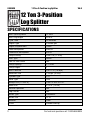
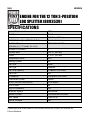
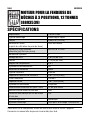
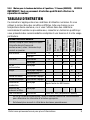
SPECIFICATIONS
Max. Splitting Force 12 tons
Max. Log Length 20.5 in.
Cycle Time 29 seconds
Engine Type 4-stroke gas
Engine Displacement
196cc
Peak Horsepower 5.63 HP
Theoretical Horsepower 6.5 HP
Torque Rating 9.59 ft-lb (13 N-m)
Start Type Recoil
Low Oil Shut Down Yes
Pump Capacity 2.1 GPM
Pump Stages 1
Max. Pressure 2,611 PSI (18 Mpa)
Reservoir Size 1.32 gal. (5 litre)
Cylinder Type 3 in.
Valve Type CGD
Wedge Size (L x W x H) 3.94 x 2.52 x 5.91 in.
Beam Size 4.72 in. (12 cm)
Vertical Operation Yes
Log Catcher Yes
Wheel Type Pneumatic
Wheel Size 12 in.
Material Steel
Finish Powder coating
12 Ton 3-Position
Log Splitter

V4.0 12 Ton 3-Position Log Splitter 8893539
Visit www.princessauto.com for more information 3
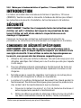
INTRODUCTION
The 12 Ton 3-Position Log Splitter is ideal for logs up to 20.5 in. Low-oil
shutdown, 29-second cycle time and 196cc 5.63 HP engine. Powder-coated
steel construction.
A separate engine manual is included. Please consult it when necessary.
SAFETY
WARNING! Read and understand all instructions before using this tool. The
operator must follow basic precautions to reduce the risk of personal injury
and/or damage to the equipment.
Keep this manual for safety warnings, precautions, operating or inspection and
maintenance instructions.
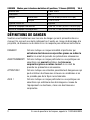
HAZARD DEFINITIONS
Please familiarize yourself with the hazard notices found in this manual. A notice
is an alert that there is a possibility of property damage, injury or death if certain
instructions are not followed.
DANGER! This notice indicates an immediate and specific hazard that will
result in severe personal injury or death if the proper precautions
are not taken.
WARNING! This notice indicates a specific hazard or unsafe practice that
could result in severe personal injury or death if the proper
precautions are not taken.
CAUTION! This notice indicates a potentially hazardous situation that may result
in minor or moderate injury if proper practices are not taken.
NOTICE! This notice indicates that a specific hazard or unsafe practice will
result in equipment or property damage, but not personal injury.
WORK AREA
1. Operate in a safe work environment. Keep your work area clean, well-lit
and free of distractions. Place lights so you are not working in a shadow.
2. Keep anyone not wearing the appropriate safety equipment away from the
work area.

8893539 12 Ton 3-Position Log Splitter V4.0
4 For technical questions call 1-800-665-8685
3. Store unused tools properly in a safe and dry location to prevent rust or
damage. Lock tools away and keep out of the reach of children.
4. Do not install or use in the presence of flammable gases, dust or liquids.
PERSONAL SAFETY
WARNING! Wear personal protective equipment approved by the Canadian
Standards Association (CSA) or American National Standards Institute (ANSI).
PERSONAL PROTECTIVE EQUIPMENT
1. Always wear impact safety goggles that provide front and side protection
for the eyes. Eye protection equipment should comply with CSA Z94.3-07
or ANSI Z87.1 standards based on the type of work performed.
2. Wear the appropriate type of full-face shield in addition to safety googles,
as the work can create chips, abrasive or particulate matter.
3. Wear gloves that provide protection based on the work materials or to
reduce the effects of tool vibration.
a. Do not wear gloves when operating a tool that can snag the material
and pull the hand into the tool.
4. Wear protective clothing designed for the work environment and tool.
5. Non-skid footwear is recommended to maintain footing and balance in the
work environment.
6. Wear steel toe footwear or steel toe caps to prevent a foot injury from
falling objects.
PERSONAL PRECAUTIONS
WARNING! DO NOT work with one person controlling the log splitter and another
handling the log. This lack of coordination can result in a crushing injury or
amputation for the person controlling the log if the wedge advances
unexpectedly. Only the log splitter operator should remove the split log.
Control the tool, personal movement and the work environment to avoid
personal injury or damage to tool.
1. Do not operate any tool when tired or under the influence of drugs, alcohol
or medications.

V4.0 12 Ton 3-Position Log Splitter 8893539
Visit www.princessauto.com for more information 5
2. Avoid wearing clothes or jewelry that can become entangled with the
moving parts of a tool. Keep long hair covered or bound.
3. Do not overreach when operating a tool. Proper footing and balance
enables better control in unexpected situations.
SPECIFIC SAFETY PRECAUTIONS
WARNING! DO NOT let comfort or familiarity with product (gained from
repeated use) replace strict adherence to the tool safety rules. If you use
this tool unsafely or incorrectly, you can suffer serious personal injury.
1. Use the correct tool for the job. This tool was designed for a specific function.
Do not modify or alter this tool or use it for an unintended purpose.
2. Do not use the tool if any parts are damage broken or misplaced. Repair or
replace the parts.
3. Only use this tool on a surface that is stable, level, dry, not slippery and
capable of sustaining the tool’s weight and its maximum load.
4. Inspect material for foreign objects such as staples, nails or debris.
Remove from material before cutting.
5. Clear debris from the splitter and the surrounding area before using.
6. Keep your limbs away from the log, wedge, hydraulic ram or work table when
operating the splitter. Do not insert your hands in between the splits and
cracks that form in the log, as they may snap shut causing personal injury.
7. Never clamp or tie the hydraulic control lever (D) in the open position.
8. Never stand on the log splitter. Serious injury could occur if it tips over or
contact is made with the cutting wedge.
9. Do not attempt to load the log onto the work table until the log pusher
has stopped.
10. Do not place the log across the work table, as this may damage the splitter.
Always split logs in the direction of the wood grain.
11. Do not attempt to split logs larger than the tool’s width or length capacity
(see Specifications), as it may cause the tool to fail and endanger you or
any bystanders.
12. Do not split multiple logs at the same time.

8893539 12 Ton 3-Position Log Splitter V4.0
6 For technical questions call 1-800-665-8685
13. Remain with the tool until it comes to a complete stop. Turn the power OFF
before leaving the area.
14. Do not leave the log or splitter under pressure.
HYDRAULIC PRECAUTIONS
DANGER! Seek immediate medical attention if hydraulic fluid under pressure
penetrates your skin. See Injection Injury precautions for instructions
before using a pressurized hydraulic system.
1. Do not touch or handle hydraulic hoses or components while under pressure.
Hydraulic fluid escaping under pressure has sufficient force to penetrate your
clothing and skin. A pinpoint hole may inject hydraulic fluid into your body.
Seek immediate medical attention if this occurs (see Injection Injury).
2. Never exceed the hydraulic system’s load capacity (see Specifications).
3. Do not adjust the hydraulic system’s relief setting. The settings are preset
by the factory.
4. Hydraulic oil under pressure is hot and can cause a burn injury if
touched, sprayed or spilled. Allow the hydraulic system to cool before
conducting maintenance.
5. Hydraulic components require regular inspection. Release all pressure
from the system before you inspect it. Replace damaged hydraulic parts
with identical manufacturer's components.
6. Do not attempt makeshift repairs to a hydraulic system. Such repairs can
fail suddenly and create a hazardous condition.
7. Hydraulic fluid has a combustible flash point of 200°F (93°F). Do not
expose the fluid to an ignition source.
8. Change your clothing immediately if sprayed with hydraulic fluid. Store
clothing or rags contaminated with hydraulic fluid in an approved metal
safety can with a spring-closing lid and venting designed to contain a fire.
9. Only use hydraulic fluid in the cylinder. Do not substitute or mix brake fluid
or any other fluid with the hydraulic fluid. This can result in a cylinder
failure and injure the user or bystander. It may also damage the cylinder.

V4.0 12 Ton 3-Position Log Splitter 8893539
Visit www.princessauto.com for more information 7
INJECTION INJURY
DANGER! Seek immediate, professional medical treatment if fluid penetrates
your skin. It may feel like a pricking or sting. Do not wait for the appearance of
symptoms. A toxic reaction can occur from the exposure. Delay in treatment
can lead to amputation or death.
Inform the medical staff that you have a fluid penetration injury as soon as you
arrive at the medical facility. The severity of the symptoms will depend on the
type of fluid injected. Bring the Safety Data Sheet for the fluid with you to the
medical facility if possible.
INJECTION PRECAUTIONS
Fluid can penetrate the skin at 100 PSI pressure. Fluid escaping under pressure
from the tool has sufficient force to penetrate your clothing and skin. Follow the
precautions below to avoid an injection injury.
1. Always check for leaks wearing a face shield, safety goggles, rubberized
gloves and protective clothes.
2. Release all pressure from the system before you inspect it.
3. Do not use your hands to detect a fluid leak. Use a large piece of wood,
cardboard or paper and watch for discolouration.
4. Replace damaged parts with identical manufacturer's components to
ensure it is rated to handle the pressure.
POWER TOOL PRECAUTIONS
1. DO NOT use any power tool with a malfunctioning power switch or control.
A power tool that fails to respond to the controls is dangerous and could
cause an injury. A qualified technician must repair and verify the power tool
is operating correctly before it can be used.
2. Do not allow the tool to run without load for an extended period of time, as
this will shorten its life.
3. Do not cover the air vents. Proper cooling of the motor is necessary to
ensure normal life of the tool.
4. Disconnect the power source before installing or servicing the tool.

8893539 12 Ton 3-Position Log Splitter V4.0
8 For technical questions call 1-800-665-8685
5. After making adjustments, make sure that any adjustment devices are
securely tightened.
6. Never force the tool. Excessive pressure could break the tool, resulting in
damage to your workpiece or serious personal injury. If your tool runs
smoothly under no load, but does not run smoothly under load, then
excessive pressure is being used.
7. Do not touch an operating motor. Motors can operate at high temperatures
and can cause a burn injury.
8. Only use accessories that are specifically designed for use with the tool.
Ensure the accessory is tightly installed.
UNPACKING
WARNING! Do not operate the tool if any part is missing. Replace the
missing part before operating. Failure to do so could result in a malfunction
and personal injury.
Remove the parts and accessories from the packaging and inspect for damage.
Make sure that all items in the parts list are included.
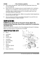
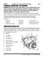
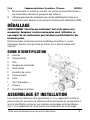
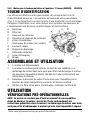
IDENTIFICATION KEY
A Beam
B Log Guard
C Wedge
D Control Valve
E Log Guide
F Lock Assembly
G Main Body
H Wheel
I Hydraulic Cylinder
J Handle
K Engine Assembly
Fig. 1

V4.0 12 Ton 3-Position Log Splitter 8893539
Visit www.princessauto.com for more information 9
ASSEMBLY & INSTALLATION
Numbered references in parenthesis (#1) refer to the included Parts List.
Letter references in parenthesis (A) refer to the included Identification Key.
Dashed numbers in parenthesis (Fig. 1-1) refer to a specific point in an
illustration or image.
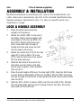
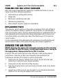
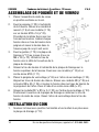
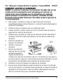
LOCK & HANDLE ASSEMBLY
1. Place the body frame assembly
upright on the ground.
2. Attach the handle (#22) to the end of
the beam. Slide a spring washer (#9)
and washer (#10) over an M10 x 16
bolt (#23). Repeat with three more
bolts. Insert each bolt through a
handle bolt hole and screw the bolt
into the beam until secure.
3. Attach the handle bar (#73) to the lock
plate (#12) with an M6 x 10 screw
(#72). Use the bolt hole to the side of
the lock plate opening.
4. Slide the bolt hole at the end of the
lock plate over the beam’s top bolt.
Secure with a washer (#10) and M10
lock nut (#11).
5. Place the lock handle (#36) over the lock shaft (#33). Align the bolt holes
in each. Slide an Ø8 washer (#35) over the M8 x 40 bolt (#34) and insert
the bolt through the bolt holes in the handle and shaft. Secure with an M8
lock nut (#37).
6. Slide the Ø37 x Ø14 x 3 washer (#32) over the lock shaft (#33). Position
the lock metal plate opening over the body frame’s bolt hole. Screw the
lock shaft into the bolt hole.
Fig. 2

8893539 12 Ton 3-Position Log Splitter V4.0
10 For technical questions call 1-800-665-8685
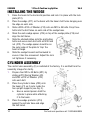
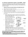
INSTALLING THE WEDGE
1. Raise the beam to the horizontal position and lock it in place with the lock
plate (#12).
2. Place the wedge (#17) on the beam with the base’s bolt holes hanging over
the edge on each side.
3. Slide a Ø20 x Ø10 x 2 Washer (#10) onto six M10 x 45 bolts. Drop three
bolts into the bolt holes on each side of the wedge base.
4. Stack the each wedge spacer (#16) on top of the wedge plate (#15) and
align the bolt holes.
5. Slide the stacked plates onto the protruding
bolts and secure each bolt with an M10 lock
nut (#12). The wedge spacer should be on
the outer edge of the plate to ‘trap’ the
beam’s flange.
6. Slide the wedge forward and backward to
ensure it has free movement. Adjust the lock
nut tightness if necessary.
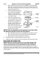
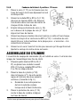
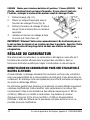
CYLINDER ASSEMBLY
The control valve assembly (D) is installed at the factory. It is omitted from the
assembly images for clarity.
1. Prepare four M10 x 40 Bolts (#21) by
sliding a Ø10 Spring Washer (#9)
and Ø20 x Ø10 x 2 Washer (#10)
onto each bolt.
2. Place the cylinder’s base (#20) onto
the beam (#1) so it rests inside the
two upright supports (see Fig. 3).
a. Have a second person hold the
cylinder in place while attaching
it to the beam.
3. Place the wedge protector (#74)
against the cylinder base and align
the bolt holes.
Fig. 3
Fig. 4

V4.0 12 Ton 3-Position Log Splitter 8893539
Visit www.princessauto.com for more information 11
4. Insert each bolt prepared in step 1 through the wedge protector, cylinder
base and beam upright bolt holes. Secure each bolt with an M10 lock nut
(#11).
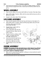
WHEEL ASSEMBLY
1. Place the tire (#39) on the wheel shaft (#48) on the side of the body frame.
2. Slide a Ø24 x Ø8 x 2 washer (#29) onto the wheel shaft and secure with an
M8 lock nut (#37)
3. Repeat on the other side of the body frame.
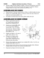
LOG GUIDE ASSEMBLY
1. Place the left log guide (#2) onto the three bolt stems on the beam (#1).
2. Slide a Ø20 x Ø10 x 2 washer (#10) and Ø10 spring washer (#9) onto each
bolt stem. Secure each bolt stem
with an M10 nut (#8).
3. Repeat steps 1 and 2 with the
right log guide (#14).
4. Push a log guard (#4) onto the
log guide receiver. Align the bolt
holes in both.
5. Prepare 2 bolts by sliding a Ø12
x Ø6 x 1.5 washer (#6) over
each M6 x 40 bolt (#7).
6. Insert two bolts through the log
guard bolt hole. Secure each
bolt with an M6 lock nut (#6).
7. Repeat steps 4 to 6 on the other
side.
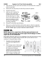
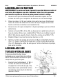
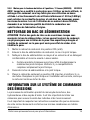
ENGINE ASSEMBLY
WARNING! The engine is heavy and could cause a back injury if you attempt
to move it unaided. Have a second person help to move it into position or
use a hoist capable of handling the load.
1. Make sure the assembled log splitter is sitting on a level surface to avoid it
tipping over during assembly.
Fig. 4

8893539 12 Ton 3-Position Log Splitter V4.0
12 For technical questions call 1-800-665-8685
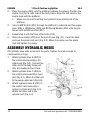
2. Place the engine (#49) onto the platform between the wheels. Position the
engine front to the right side of the body frame. Align the bolt holes in the
engine base with the platform.
a. Make sure to avoid crushing the hydraulic hose sticking out of the
platform.
3. Insert a M8*40 bolt (#34) through the platform’s underside and the engine
base. Slide a Ø8 Washer (#35) and Ø8 Spring Washer (#50) onto the pin.
Secure with an M8 Lock Nut (#37).
4. Repeat step 3 with the three other bolts (#34).
5. Slide a hose clamp (#48) over the end of hose (Fig. 4-1). Insert the hose
end over the pump inlet port (Fig. 4-2). Move the clamp over the pump
inlet and tighten the clamp.
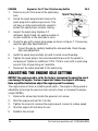
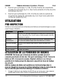
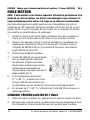
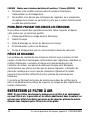
ASSEMBLY HYDRAULIC HOSES
All hydraulic hose ends screw onto the ports. Tighten the ends enough to
compress the o-rings.
1. Attach hydraulic hose A (#62) to
the control valve assembly’s (D)
output port (Fig. 5-2). Connect the
other end to the body frame port
(Fig. 5-6) leading to the oil tank.
2. Attach hydraulic hose C (#63) to
the control valve assembly’s input
port (Fig. 5-1). Attach the other end
to the pump output port (Fig. 5-5).
3. Attach hydraulic hose B (#61) to
the control valve assembly’s
center’s cylinder port (Fig. 5-3).
Attach the other end to the
cylinder port (Fig. 5-4).
Fig. 5

V4.0 12 Ton 3-Position Log Splitter 8893539
Visit www.princessauto.com for more information 13
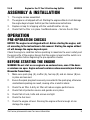
OPERATION
PRE-INSPECTION
Before each use inspect the log splitter’s components for damage or wear.
Component Problem
Hoses Inspect for exposed wire mesh and leaks. Replace all worn or
damaged hoses before starting engine.
Hydraulic fittings Inspect for cracks and leaks. Replace all damaged fitting
before starting engine.
Nuts and Bolts Check for loose bolts. Tighten any that are found.
Beam Apply grease to beam surface
Moving Parts Clear debris
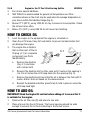
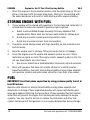
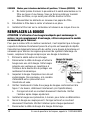
OPERATING THE LOG SPLITTER
CAUTION! Do not force the log splitter for more than 5 seconds to split hard
wood. This may damage the tool. Rotate the log 90 degrees and attempt
again. Discard the log if unable to split, as it exceeds the splitting force
capacity of this tool.
NOTICE! The log splitter does not ship with hydraulic oil in the tank. Fill and
bleed the hydraulic system per Care and Maintenance instructions to avoid
damaging the log splitter.
1. Cut the log down to a height of 20-1/2 in. or less to ensure that it will fit
between the wedge and the beam platform.
2. Cut narrower logs in a horizontal position and wider logs in the vertical
position. To change the position:
a. Loosen the lock assembly (F) and pull down on the handle (J) to raise
the beam to the horizontal position or push the handle up to lower the
beam to a vertical position.
b. Tighten the lock assembly to keep the beam in place.
3. Place the log onto the beam (A) and bottom platform.
4. Reposition the log on the beam platform so the wood grain is aligned with
the wedge. Ensure that the log is stable on the log guides (E) and properly

8893539 12 Ton 3-Position Log Splitter V4.0
14 For technical questions call 1-800-665-8685
seated on the beam platform to ensure that the pushing force will remain
constant during splitting.
5. Make sure that the log will be applied against the wedge’s full depth.
Splitting with just the top of the wedge may damage the wedge.
6. Loosen the oil tank cap (#26), but do not remove it.
7. Start the engine per the instructions in the accompanying engine manual.
8. Two hands are required to operate the log splitter. Maintain your hands on
the control until the log is completely split.
9. Release the control and the wedge will return to the starting position.
10. Remove wood pieces from the splitter and clear debris from the
surrounding area.
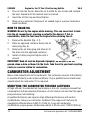
FREEING A JAMMED LOG
WARNING! Do not attempt to remove a jammed log with your hands or with
hammer blows. The wood is under pressure and could separate and launch
without warning, causing an injury to you or a bystander.
A log may jam against the wedge without splitting. The following procedure can
free the log. The intent is to remove the jammed log without splitting it.
1. Release the control and allow the wedge to return to the starting position. This
may free the log.
2. Place a triangle-shaped split log against the beam platform. The edge is
pointing toward the unsplit log.
3. Advance the wedge and unsplit log forward, stopping the ram before the log
touches the triangle-shaped log.
4. Insert the narrow edge of the triangle-shaped log under the jammed log.
5. Start the log splitter and push the triangle-shaped log and unsplit log
against the beam platform. Stop advancing before the wedge touches the
triangle-shaped log. This should raise the unsplit log up and off the wedge.
6. Repeat with larger triangle-shaped logs until the unsplit log is free from the
wedge.
7. Discard the jammed log and split it by another method.

V4.0 12 Ton 3-Position Log Splitter 8893539
Visit www.princessauto.com for more information 15
CARE & MAINTENANCE
1. Maintain the tool with care. A tool in good condition is efficient, easier to
control and will have fewer problems.
2. Inspect the tool components periodically. Repair or replace damaged or
worn components. Only use identical replacement parts when servicing.
3. Follow instructions for lubricating and changing accessories.
4. Only use accessories intended for use with this tool.
5. Keep the tool handles clean, dry and free from oil/grease at all times.
6. Maintain the tool’s labels and name plates. These carry important information.
If unreadable or missing, contact Princess Auto Ltd. for replacements.
WARNING! Only qualified service personnel should repair the tool. An
improperly repaired tool may present a hazard to the user and/or others.
MAINTENANCE MODE
Place the log splitter into maintenance mode to allow safe handling.
1. Turn off engine and allow to cool.
2. Move the control valve handle forward and backward to relieve hydraulic
pressure in the system.
3. Proceed with maintenance.
HYDRAULIC RAM MAINTENANCE
Monthly maintenance is recommended for the hydraulic ram. Any restrictions due
to dirt, rust, etc. can cause the either slow movement or extremely rapid jerks,
damaging the internal components. The following steps are designed to keep the
cylinder maintained and operational.
1. Follow lubrication instructions.
2. Visually inspect for cracked welds, bent, loose, missing parts or hydraulic
oil leaks.
3. Inspect the hydraulic ram immediately if it was subjected to an abnormal load
or shock load.

8893539 12 Ton 3-Position Log Splitter V4.0
16 For technical questions call 1-800-665-8685
4. Remove any hydraulic cylinder from service that is damaged, worn down or
operates abnormally, until repaired by an authorized service technician.
5. Check and maintain the ram oil level.
6. Always store the hydraulic ram in the fully retracted position. This will help
protect critical areas from corrosion.
7. Do not use brake or transmission fluids or regular motor oil as they can
damage the seals. Always purchase and use products labeled Hydraulic Oil.
REPLACING HYDRAULIC OIL
Replace the hydraulic oil after every 400 hours of tool use.
1. Return the wedge (C) to the starting position and shut the motor OFF.
Allow time for the tool to cool down.
2. Place a 5 litre container below the oil outlet.
3. Removed the oil tank cap (#26).
4. Unscrew the oil drain bolt (#40) and combination washer (#41). Set both
aside. The oil will drain out of the tank.
5. Slide the combination washer onto the oil drain bolt and screw it back into
the tank. Tighten the screw and wipe up any oil on the beam.
6. Refill the hydraulic oil reservoir. See Specifications for the proper amount of
hydraulic oil. A funnel may be needed depending on the angle.
7. Follow steps for Bleeding the Hydraulic System.
8. Clean the area around the oil outlet.
9. Clean the oil tank cap’s threads and screw it back into place. Tighten to
ensure it is sealed.
BLEEDING THE HYDRAULIC SYSTEM
Bleed excess air from the hydraulic system as follows:
1. Fill the tank with hydraulic fluid.
2. Wait 5 minutes for trapped air to rise to the surface.
3. Check the oil filler hole and if necessary, top off with more hydraulic oil.
4. Restore the oil filler screw.

V4.0 12 Ton 3-Position Log Splitter 8893539
Visit www.princessauto.com for more information 17
5. Test the ram several times for proper operation before putting it into use. Do
not use the ram if it still does not appear to be working properly. Have a
qualified service technician service or repair the hydraulic system.
SHARPENING THE WEDGE
The wedge will dull after repeated use. Remove burrs and nicks from the edge
with a file.
LUBRICATION
Inspect and lubricate the tool when required.
1. Apply a suitable oil or grease to all points where metal contacts metal and
any hinges or pivot points.
2. Fully extend the ram, then apply grease to the piston. Use a tool to apply
the grease instead of your hands to avoid the possibility of an unexpected
retraction.
3. Remove each wheel and grease the wheel shafts (#48). Reinstall the wheels.
STORAGE
When not in use for an extended period, apply a thin coat of lubricant to the
steel parts to avoid rust. Remove the lubricant before using the tool again.
DISPOSAL
Recycle a tool damaged beyond repair at the appropriate facility.
Contact your local municipality for a list of disposal facilities or by-laws for
electronic devices, batteries, oil or other toxic liquids.
IMPORTANT! DO NOT pollute the environment by allowing uncontrolled
discharge of waste oil.
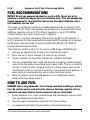
HYDRAULIC FLUID
Do not drain hydraulic oil into the sewer system or dispose in an uncontrolled
location. Hydraulic fluid may take more than a year to breakdown in the
environment and the ingredients may still be toxic. Contact your local
municipality for proper disposal instructions or locations.

8893539 12 Ton 3-Position Log Splitter V4.0
18 For technical questions call 1-800-665-8685
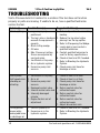
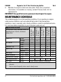
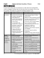
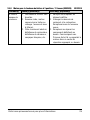
TROUBLESHOOTING
Visit a Princess Auto Ltd. location for a solution if the tool does not function
properly or parts are missing. If unable to do so, have a qualified technician
service the tool.
Problem(s) Possible Cause(s) Suggested Solution(s)
Fails to split logs 1. Log is improperly
positioned
2. The log’s size or hardness
exceeds the equipment’s
capacity.
3. Blunt cutting wedge.
4. Oil leaks
5. Max. Pressure Limiting
Screw was adjusted by
non-technician.
6. Insufficient oil to pump.
7. Air in hydraulic system
8. Excessive pump inlet
vacuum
1.
Refer to Operation for correct log
loading.
2. Reduce the log sizes before
placing it on the log splitter.
3. Refer to Sharpening the Wedge.
4. Locate leak(s) and contact a
qualified technician.
5. Contact qualified technician to
reset to factory specifications.
6. Check oil level and fill if needed.
7. Refer to Bleeding the Hydraulic
System.
8. Check pump inlet hose for
blockage or kinks
Slow cylinder
shaft speed when
extending or
retracting
1. Insufficient oil to pump
2. Air in oil
3. Excessive pump inlet
vacuum
4. Damaged control valve
5. Internal control valve leak
6. Internally damaged
cylinder
7. Engine Control out of
adjustment
1. Check oil level in oil tank
2. Check oil level in oil tank
3. Check pump inlet hose for
blockage or kinks
4. Return control valve for
authorized repair
5. Return control valve for
authorized repair
6. Return control valve for
authorized repair
7. Adjust idle control nuts
The log pusher
moves jerkily,
making odd noise
or vibrating a lot.
1. Lack of hydraulic oil
2. Excessive air in the
hydraulic system.
1. Check oil level and fill if needed.
2. Refer to Bleeding the Hydraulic
System.

V4.0 12 Ton 3-Position Log Splitter 8893539
Visit www.princessauto.com for more information 19
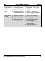
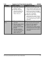
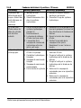
Problem(s) Possible Cause(s) Suggested Solution(s)
Oil leaks around
cylinder ram or
from other
points.
1. Air sealed in hydraulic
system while operating.
2. Oil Drain Bolt is not tight.
3. Hydraulic Control Valve
Assembly and/or seal(s)
worn.
1. Loosen Bleed Screw by some
rotations before operating the
log splitter.
2. Tighten the Oil Drain Bolt.
3. Check valve assembly and seals.
Replace either if necessary.
Cylinder rod will
not move
1. Insufficient oil to pump
2. Blocked hydraulic lines
3. Blocked control valve
4. Damaged control valve
5. Internal cylinder leak
1. Check oil level in oil tank
2. Flush and clean the splitter
hydraulic system
3. Flush and clean the splitter
hydraulic system
4. Return control valve for
authorized repair
5. Return control valve for
authorized repair

8893539 12 Ton 3-Position Log Splitter V4.0
20 For technical questions call 1-800-665-8685
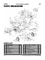
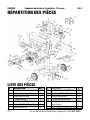
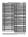
PARTS BREAKDOWN
PARTS LIST
#
DESCRIPTION
QTY
1 Beam 1
2 Log Guide (Left) 1
3 Tube Cap 2
4 Log Guard 2
5 M6 Lock Nut 4
6 Ø12 x Ø6 x 1.5 Washer 4
7 M6 x 40 Bolt 4
8 M10 Nut 6
9
Ø
10 Spring Washer 14
10
Ø
20 x
Ø
10 x 2 Washer 27
11 M10 Lock Nut 12
La page est en cours de chargement...
La page est en cours de chargement...
La page est en cours de chargement...
La page est en cours de chargement...
La page est en cours de chargement...
La page est en cours de chargement...
La page est en cours de chargement...
La page est en cours de chargement...
La page est en cours de chargement...
La page est en cours de chargement...
La page est en cours de chargement...
La page est en cours de chargement...
La page est en cours de chargement...
La page est en cours de chargement...
La page est en cours de chargement...
La page est en cours de chargement...
La page est en cours de chargement...
La page est en cours de chargement...
La page est en cours de chargement...
La page est en cours de chargement...
La page est en cours de chargement...
La page est en cours de chargement...
La page est en cours de chargement...
La page est en cours de chargement...
La page est en cours de chargement...
La page est en cours de chargement...
La page est en cours de chargement...
La page est en cours de chargement...
La page est en cours de chargement...
La page est en cours de chargement...
La page est en cours de chargement...
La page est en cours de chargement...
La page est en cours de chargement...
La page est en cours de chargement...
La page est en cours de chargement...
La page est en cours de chargement...
La page est en cours de chargement...
La page est en cours de chargement...
La page est en cours de chargement...
La page est en cours de chargement...
La page est en cours de chargement...
La page est en cours de chargement...
La page est en cours de chargement...
La page est en cours de chargement...
La page est en cours de chargement...
La page est en cours de chargement...
La page est en cours de chargement...
La page est en cours de chargement...
La page est en cours de chargement...
La page est en cours de chargement...
La page est en cours de chargement...
La page est en cours de chargement...
La page est en cours de chargement...
La page est en cours de chargement...
La page est en cours de chargement...
La page est en cours de chargement...
La page est en cours de chargement...
La page est en cours de chargement...
La page est en cours de chargement...
La page est en cours de chargement...
La page est en cours de chargement...
La page est en cours de chargement...
La page est en cours de chargement...
La page est en cours de chargement...
La page est en cours de chargement...
La page est en cours de chargement...
La page est en cours de chargement...
La page est en cours de chargement...
La page est en cours de chargement...
La page est en cours de chargement...
La page est en cours de chargement...
-
 1
1
-
 2
2
-
 3
3
-
 4
4
-
 5
5
-
 6
6
-
 7
7
-
 8
8
-
 9
9
-
 10
10
-
 11
11
-
 12
12
-
 13
13
-
 14
14
-
 15
15
-
 16
16
-
 17
17
-
 18
18
-
 19
19
-
 20
20
-
 21
21
-
 22
22
-
 23
23
-
 24
24
-
 25
25
-
 26
26
-
 27
27
-
 28
28
-
 29
29
-
 30
30
-
 31
31
-
 32
32
-
 33
33
-
 34
34
-
 35
35
-
 36
36
-
 37
37
-
 38
38
-
 39
39
-
 40
40
-
 41
41
-
 42
42
-
 43
43
-
 44
44
-
 45
45
-
 46
46
-
 47
47
-
 48
48
-
 49
49
-
 50
50
-
 51
51
-
 52
52
-
 53
53
-
 54
54
-
 55
55
-
 56
56
-
 57
57
-
 58
58
-
 59
59
-
 60
60
-
 61
61
-
 62
62
-
 63
63
-
 64
64
-
 65
65
-
 66
66
-
 67
67
-
 68
68
-
 69
69
-
 70
70
-
 71
71
-
 72
72
-
 73
73
-
 74
74
-
 75
75
-
 76
76
-
 77
77
-
 78
78
-
 79
79
-
 80
80
-
 81
81
-
 82
82
-
 83
83
-
 84
84
-
 85
85
-
 86
86
-
 87
87
-
 88
88
-
 89
89
-
 90
90
-
 91
91


Powerfist 8893539 Le manuel du propriétaire
- Catégorie
- Fendeuses de bûches
- Taper
- Le manuel du propriétaire
dans d''autres langues
- English: Powerfist 8893539 Owner's manual
Documents connexes
Autres documents
-
Power Fist 8727679 Le manuel du propriétaire
-
Detail K2 9204520 Le manuel du propriétaire
-
-
-
Southland SLS20825 Mode d'emploi
-
 Red Rock 9015918 Le manuel du propriétaire
-
Woods 605000 Manuel utilisateur
-
Swisher LS722A Le manuel du propriétaire
-
Oregon 9217530 Le manuel du propriétaire
-
Texas Power Split 2100V Manuel utilisateur
