Rotel RSX-1058 Le manuel du propriétaire
- Taper
- Le manuel du propriétaire


2
RSX-1058 Surround Sound Receiver
> 10 cm
> 4 in
> 10 cm
> 4 in
> 10 cm
> 4 in
> 10 cm > 4 in
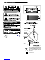
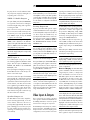
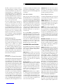
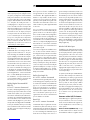
Rotel products are designed to comply with international directives on the
Restriction of Hazardous Substances (RoHS) in electrical and electronic
equipment and the disposal of Waste Electrical and Electronic Equipment
(WEEE). The crossed wheelie bin symbol indicates compliance and that
the products must be appropriately recycled or processed in accordance
with these directives.
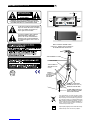
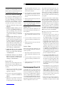
This symbol means that this unit is double insulated. An earth or ground
connection is not required.
H=150 mm
RSX-1058

3
English
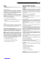
Notice
The
COMPUTER I/O connection
should be handled by authorized persons only.
FCC Information
This equipment has been tested and found to comply with the limits for a Class B digital device,
pursuant to Part 15 of the FCC Rules. These limits are designed to provide reasonable protec-
tion against harmful interference in a residential installation. This equipment generates, uses
and can radiate radio frequency energy and, if not installed and used in accordance with the
instruction, may cause harmful interference to radio communications.
However, there is no guarantee that interference will not occur in a particular installation. If
this equipment does cause harmful interference to radio or television reception, which can be
determined by turning the equipment off and on, the user is encouraged to try to correct the
interference by one or more of the following measures:
• Reorient or relocate the receiving antenna.(TV, radio, etc.)
• Increase the separation between the equipment and receiver
• Connect the equipment to an outlet on circuit different from that to which the receiver is
connected.
• Consult the dealer or an experienced radio/TV technician for additional help.
Caution
This device complies with part 15 of the FCC Rules operation is subject to the following to condi-
tions: (1) This device may not cause harmful interference, and (2) this device must accept any
interference received, including interference that may cause undesired operation.
NOTE TO CATV SYSTEM INSTALLER: Call the CATV system or antenna
installer’s attention to Article 820-40 of the NEC. This provides guidelines for proper grounding
and, in particular, specifies that the cable ground shall be connected to the grounding system of
the building, as close to the point of cable entry as practical. See installation diagram.
NOTE: This equipment has been tested and found to comply with the limits for a Class B
digital device, pursuant to Part 15 of the FCC Rules. These limits are designed to provide rea-
sonable protection against interference in a residential installation. This equipment generates
and can radiate radio frequency energy and, if not installed and used in accordance with the
instructions, may cause interference to radio or TV communications. There is no guarantee that
interference will not occur in a particular installation. If this equipment does cause interference
to radio or television reception, which can be determined by turning the equipment off and on,
try to correct the interference by one or more of the following measures:
• Reorient or relocate the receiving antenna.
• Increase the separation between the unit and the television tuner.
• Connect the unit to an AC power outlet on a different electrical circuit.
• Consult your authorized Rotel retailer for assistance.
Important Safety Instructions
WARNING: There are no user serviceable parts inside. Refer all servicing to qualified
service personnel.
WARNING: To reduce the risk of fire or electric shock, do not expose the unit to mois-
ture or water. Do not expose the unit to dripping or splashing. Do not place objects filled with
liquids, such as vases, on the unit. Do not allow foreign objects to get into the enclosure. If the
unit is exposed to moisture, or a foreign object gets into the enclosure, immediately discon-
nect the power cord from the wall. Take the unit to a qualified service person for inspection
and necessary repairs.
Read all the instructions before connecting or operating the component.
Keep this manual so you can refer to these safety instructions.
Heed all warnings and safety information in these instructions and on the product itself. Fol-
low all operating instructions.
Clean the enclosure only with a dry cloth or a vacuum cleaner.
Do not use this unit near water.
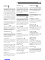
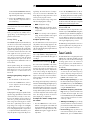
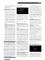
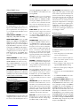
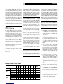
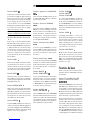
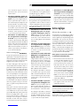
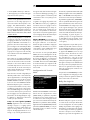
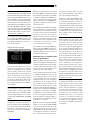
You must allow a minimum 10 cm or 4 inches of unobstructed clearance around
the unit. Do not place the unit on a bed, sofa, rug, or similar surface that could block the ven-
tilation openings. If the unit is placed in a bookcase or cabinet, there must be ventilation of the
cabinet to allow proper cooling.
Keep the component away from radiators, heat registers, stoves, or any other appliance that
produces heat.
The unit must be connected to a power supply only of the type and voltage specified on the rear
panel. (USA: 120 V/60Hz, EC: 230V/50Hz)
Connect the component to the power outlet only with the supplied power supply cable or an
exact equivalent. Do not modify the supplied cable. A polarized plug has two blades, with one
wider than the other. A grounding plug has two blades plus a third grounding prong. These are
provided for your safety. Do not defeat grounding and/or polarization safety provisions. If the
supplied plug does not fit your outlet, please consult an electrician for replacement of the ob-
solete outlet. Do not use extension cords.
The main plug of the power cordset is a disconnect device of the apparatus. In order to com-
pletely disconnect the apparatus from the supply mains, the main plug of the power cordset
should be unplugged from the mains (AC) outlet. The stand-by LED indicator will not be lit up
to show the power cord is unplugged.
Do not route the power cord where it will be crushed, pinched, bent, exposed to heat, or dam-
aged in any way. Pay particular attention to the power cord at the plug and where the cord
exits the back of the unit.
The power cord should be unplugged from the wall outlet during a lightning storm or if the unit
is to be left unused for a long period of time.
Use only accessories specified by the manufacturer.
Use only with a cart, stand, rack, bracket or shelf system recommended by Rotel. Use caution
when moving the unit in a stand or rack to avoid injury from a tip-over.
Use Class 2 wiring for speaker connections to ensure proper installation and minimize the risk
of electrical shock.
Immediately stop using the component and have it inspected and/or serviced by a qualified
service agency if:
• The power supply cord or plug has been damaged.
• Objects have fallen or liquid has been spilled into the unit.
• The unit has been exposed to rain.
• The unit shows signs of improper operation
• The unit has been dropped or damaged in any way
WARNING: The master power switch is located on the rear panel. The unit must be lo-
cated in the open area allowing unobstructed access to the main power switch.

4
RSX-1058 Surround Sound Receiver
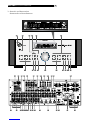
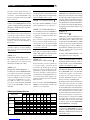
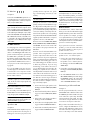
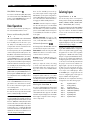
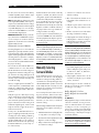
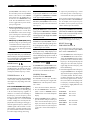
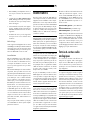
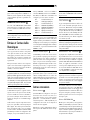
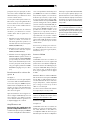
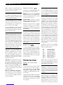
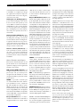
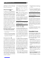
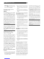
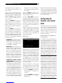
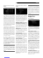
1: Controls and Connections
Commandes et Branchements
H=150 mm
RSX-1058

5
English
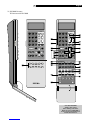
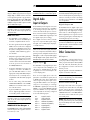
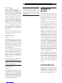
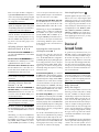
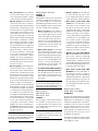
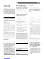
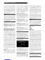
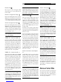
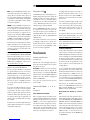
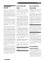
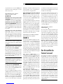
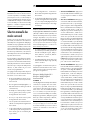
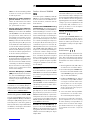
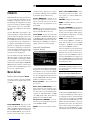
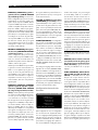
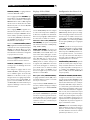
2: RR-1060 Remote
Télécommande RR-1060
Turn off the RSX-1058
and the entire system
before making connections!
Éteignez toujours le RSX-1058 et
tout le système avant d’effectuer le
moindre branchement !
1 2 3
4 5 6
7 8 9
+10 0 X
CM
SR
ENT
FRQ DIRECT
MENUGUIDE
TUNE PRESET
FM MONO BAND
CTR
SUB SUR
SEARCH
-
SEARCH+
OSD
ON OFF
SMT
MUTE
CH VOL
POWER
SMART
MEM
AUD CD TUN TAPE EXT
V1 V2 V3 V4
V5
DEVICE / INPUT
RR-1060
LIGHT
DVD
RESUME REPEAT SLOWGOTOA - B
INPUT 1 INPUT 2 RECORDTV/VCRINPUT 3
ASPECT DISP OUTPUTPOPPIP
1 2 3
4 5 6
7 8 9
+10 0 X
ON OFF
SMT
MUTE
CM
SR
ENT
FRQ DIRECT
MENUGUIDE
TUNE PRESET
FM MONO BAND
CTR
SUB SUR
SEARCH
-
SEARCH+
OSD
CD
DISC2DISC1 DISC3 DISC4 DISC5
PROG RANDOM REPEAT DISC
-
DISC+
DISPLAY AUDIO ZOOMSBTITLEANGLE
DISP
TAPE2 PHONO
TONE D-SLT
EQ DYN REC
ZONE SUR+
2CH PL M 5CH 7CH
PL C
CH VOL
POWER
SMART
MEM
DIGEST OPENP-SCANTITLE
SCAN
PTY P-TUN
TP TA
POWER SETUP


8
RSX-1058 Surround Sound Receiver
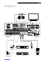
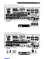
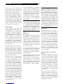
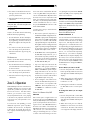
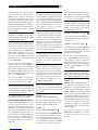
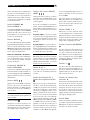
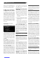
5: TV Analog Connections
Branchements d’un téléviseur
6: DVD Player Analog Connections
Branchements d’un lecteur de DVD en liaison analogique
�� ����

9
English
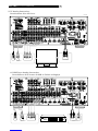
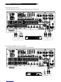
8: Cable, Satellite, or HDTV Analog Connections
Branchements d’un décodeur câble, satellite ou HDTV
7: DVD-A or SACD Player Connections
Branchements d’un lecteur de DVD-Audio ou SACD

10
RSX-1058 Surround Sound Receiver
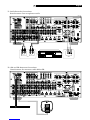
9: VCR Analog Connections
Branchement d’un magnétoscope (VCR) en liaison analogique
10: CD Player/CDR Recorder Connections
Branchement d’un lecteur/enregistreur de CD/CD-R


12
RSX-1058 Surround Sound Receiver
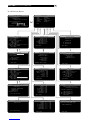
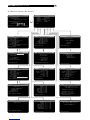
13: On-Screen Menus

13
English
Contents
Boxed numbers refer to RSX-1058 illustration.
Boxed letters refer to RR-1060 illustration.
FCC Information ..................................................3
Caution ...............................................................3
Important Safety Instructions ..................3
1: Controls and Connections ................................4
2: RR-1060 Remote .............................................5
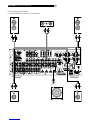
3: Connecting the Speakers .................................6
4: Digital Video Connections ................................7
5: TV Analog Connections ....................................8
6: DVD Player Analog Connections .......................8
7: DVD-A or SACD Player Connections ..................9
8: Cable, Satellite, or HDTV Analog Connections ...9
9: VCR Analog Connections ................................10
10: CD Player/CDR Recorder Connections ..........10
11: Audio Recorder Connections .........................11
12: AM and FM Antennae Connections ...............11
13: On-Screen Menus ........................................12
About Rotel .......................................... 15
Getting Started ..................................... 15
Key Features .....................................................15
Unpacking ........................................................16
Placement ........................................................16
CONNECTIONS 16
Analog Audio Inputs & Outputs ............. 16
CD Inputs ....................................................16
TAPE Inputs .................................................16
TAPE Outputs ..............................................16
VIDEO 1–5 Audio Inputs .............................16
VIDEO 1–2 Audio Outputs ...........................17
MULTI Inputs .............................................17
Speaker Outputs .........................................17
Preamp Outputs .........................................17
ZONE 2–4 Audio Outputs ............................17
Video Inputs & Outputs ........................ 17
VIDEO 1–3 Composite Video Inputs ............18
VIDEO 1–2 Composite Video Outputs ..........18
VIDEO 1–3 S-Video Inputs ..........................18
VIDEO 1–2 S-Video Outputs .......................18
VIDEO 1–3 Component Video Inputs ..........18
VIDEO 1–4 HDMI Inputs ............................18
TV Monitor Outputs ..................18
ZONE OUT Video Outputs ............................19
Digital Audio Input & Outputs ............... 19
Digital Inputs ..............................................19
Digital Outputs ............................................19
Other Connections ................................ 19
AC Input .....................................................19
Master Power Switch ...................................19
12V TRIGGER Connections ...........................20
REM IN Jacks .............................................20
IR OUT Jacks ...............................................20
Computer I/O .............................................20
Making Connections .............................20
CD Player .............................................20
DVD Player ..................20
Cable, Satellite, HDTV Tuner
....................................21
Audio Recorder ..............................21
VCR or Digital Video Recorder
...........21
DVD-A or SACD Player ................................21
TV Monitor ...............................22
Speakers ....................................................22
Connecting a Subwoofer ..............................22
Amplifiers ...................................................23
AM Antenna ................................................23
FM Antenna ...............................................23
OPERATING THE RSX-1058 23
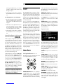
Front Panel Overview ...........................23
Front-panel Display ....................................24
Remote Sensor ............................................24
Remote Control Overview .....................24
Using the RR-1060
AUDIO Button .............................................24
Overview of Buttons and Controls .........24
STANDBY Button
POWER Button ............................................24
ON/OFF Buttons .........................................24
VOLUME Knob
VOLUME Buttons .........................................24
MUTE Buttons .......................................24
LIGHT Button ..............................................24
DEVICE/INPUT Buttons ...................24
D-SLT Button ...............................................24
SEL Button ..................................................25
REC Button ..................................................25
ZONE Buttons .......................................25
UP/DOWN Buttons ......................................25
+/– Buttons ...............................................25
Speaker Selection Buttons ...........................25
EQ Button ...................................................25
TONE Button ...............................................25
Surround Mode Buttons ........................25
SUR+ Button ...............................................25
DYN Button .................................................25
MENU/OSD Button ......................................25
ENTER Button ..............................................25
BAND Buttons .......................................25
TUNING Buttons ....................................25
MEM Buttons ........................................25
NUMERIC Buttons .................................25
DIRECT Button
FRQ DIRECT Button .....................................25
MONO Button
FM MONO Button ........................................25

14
RSX-1058 Surround Sound Receiver
TUNE Button
PRESET Button
P-TUN Button ..............................................25
SCAN Button ...............................................25
RDS/RBDS Buttons .....................................26
Basic Operations ...................................26
Power and Standby On/Off ......26
Volume Adjustments .............................26
Muting the Sound .................................26
Selecting Inputs ....................................26
Input Buttons .................................26
Selecting a Source Input from the Front Panel
................................................27
Selecting a Source from the Remote
.......................................................27
Selecting the Same Input for all Outputs
...............................................27
Selecting Digital Inputs ...............................27
Overview of Surround Formats ..............27
Dolby Surround
Dolby Pro Logic II ..............................................27
Dolby Digital .....................................................28
DTS 5.1
DTS 96/24 ........................................................28
DTS Neo:6 .........................................................28
Dolby Digital Surround EX
DTS-ES6.1 and 7.1 Channel Surround .................28
Dolby Pro Logic IIx
6.1 and 7.1 Channel Surround ...........................29
Rotel XS
6.1 and 7.1 Channel Surround ...........................29
DSP Music Modes ..............................................29
2Ch/5Ch/7Ch Stereo Formats ...........................29
Other Digital Formats ...........................29
Automatic Surround Modes ...................30
Manually Selecting Surround Modes ......30
Dolby Digital 5.1 discs
Dolby Digital Surround EX discs
................................................30
Dolby Digital 2.0 discs ..............31
DTS 5.1 discs
DTS 96/24 discs
DTS-ES 6.1 discs .......................31
Digital Stereo discs
(PCM, MP3, and HDCD) ............31
Analog Stereo ..........................32
Other Settings ......................................32
Speaker Level .......................................32
Group Delay .........................................33
Dynamic Range ..........................................33
Contour/Tone Settings ..........................33
Cinema EQ ..................................................33
Tuner Controls ......................................33
BAND Buttons ...................................... 34
TUNING Buttons ................................... 34
MEMORY Button .................................. 34
NUMERIC Buttons:
Station Presets .............................. 34
DIRECT Button
FRQ DIRECT Button ................................... 34
MONO Button
FM MONO Button .......................................35
TUNE Button
PRESET Button
P-TUN Button .............................................35
SCAN Button ...............................................35
RDS and RBDS Tuning ...........................35
DISP Button ................................................35
PTY Button .................................................35
TP Button ....................................................36
TA Button ....................................................36
Zones 2–4 Operation ............................36
Zones 2–4 Power On/Off ................................36
Controlling Zones 2–4 from the Main Room
..............................36
Controlling Zones 2–4 from the Remote Location
................................................37
SETUP 37
Menu Basics ......................................... 37
Navigation Buttons ...............................37
System Status ....................................................37
Main Menu ........................................................38
Configuring Inputs ................................38
Input Setup .......................................................38
Multi Input Setup ..............................................39
Dolby Pro Logic IIx ............................................39
DTS Neo:6 ........................................................ 40
Configuring Speakers and Audio ............40
Understanding Speaker Configuration .............. 40
Speaker Setup ...................................................41
Advance Speaker Setup .....................................41
Subwoofer Setup ...............................................42
Test Tone ...........................................................43
Delay Setup ......................................................43
Contour Setup .................................................. 44
Miscellaneous Settings ..........................44
Other Options ................................................... 44
Video/HDMI Setup ............................................45
Zones 2–4 Setup ..............................................45
Default Setup ....................................................45
MORE INFORMATION 46
Troubleshooting ....................................46
Specifications .......................................47
Audio ................................................................47
Video ................................................................47
FM Tuner ...........................................................47
AM Tuner ..........................................................47
General .............................................................47

15
English
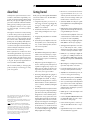
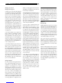
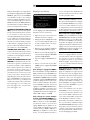
About Rotel
A family whose passionate interest in music
led them to manufacture high fidelity com-
ponents of uncompromising quality founded
Rotel 45 years ago. Through the years that
passion has remained undiminished and the
family goal of providing exceptional value
for audiophiles and music lovers regard-
less of their budget, is shared by all Rotel
employees.
The engineers work as a close team, listening
to, and fine tuning each new product until it
reaches their exacting musical standards. They
are free to choose components from around
the world in order to make that product the
best they can. You are likely to find capacitors
from the United Kingdom and Germany, semi
conductors from Japan or the United States,
while toroidal power transformers are manu-
factured in Rotel’s own factory.
Rotel’s reputation for excellence has been
earned through hundreds of good reviews
and awards from the most respected review-
ers in the industry, who listen to music every
day. Their comments keep the company true
to its goal - the pursuit of equipment that is
musical, reliable and affordable.
All of us at Rotel, thank you for buying this
product and hope it will bring you many
years of enjoyment.
Getting Started
Thank you for purchasing the Rotel RSX-1058
Surround Sound Receiver. The RSX-1058 is
four products in one:
1. A digital audio/video processor for a
wide range of formats including Dolby
Surround®, Dolby Digital®, DTS® and
HDCD® source material.
2. A full-featured audio/video control cen-
ter for analog and digital source compo-
nents.
3. A high-quality AM/FM tuner with RDS
capability.
4. A 5-channel power amplifier to drive two
front speakers (or two center back speak-
ers), a center channel speaker, and two
rear surround speakers.
Key Features
• Rotel’s Balanced Design Concept combines
advanced circuit board layout, compre-
hensive parts evaluation, and extensive
listening tests for superior sound and long
term reliability.
• Dolby® Pro Logic IIx®
decoding (for 5.1, 6.1,
and 7.1 channel systems) with improved
separation and frequency response for
Dolby Surround® matrix encoded record-
ings. Can be optimized for Music or Cin-
ema sources, Pro Logic® or Games.
• Automatic Dolby Digital® decoding Dol-
by Digital® 2.0, Dolby Digital® 5.1, and
Dolby Digital Surround EX® recordings.
• Automatic decoding for DTS® 5.1 channel,
DTS-ES® Matrix 6.1 channel, DTS-ES® Dis-
crete 6.1 channel, and DTS 96/24 digital
recordings.
• Rotel XS (eXtended Surround) automatical-
ly ensures proper decoding and optimum
performance from any multichannel digi-
tal signal on 6.1 and 7.1 channel systems.
Always active in any system with center
back speaker(s), Rotel XS even works with
signals that would not otherwise activate
the proper decoding (such as non-flagged
DTS-ES and Dolby Surround EX discs) or
for which there is no extended surround
decoder (such as DTS 5.1, Dolby Digital
5.1, and even Dolby Pro Logic II decoded
Dolby Digital 2.0 recordings).
• DTS® Neo:6® Surround modes for deriv-
ing surround channels for 5.1, 6.1 or 7.1
channel systems from 2-channel stereo or
matrix surround recordings. Can be opti-
mized for Music or Cinema sources.
• Automatic HDCD® decoding for signals
from High Definition Compatible Digital®
compact discs.
• DVD-A high-resolution multichannel audio
signals are automatically detected when
using an HDMI input connection.
• Surround modes for playback of surround
sound material on 2 channel and 3 chan-
nel systems for total compatibility.
• Automatic decoding of digital signals from
MP3 (MPEG-1 Audio Layer 3) players.
• Analog input and output video connections
for use with Composite video, S-Video,
and Component Video signals, including
conversion to Component Video output.
• HDMI (Ver. 1.1) switching for digital vid-
eo signals up to 1080p and downscal-
ing from 1080i to 480p/576p. Compat-
ible with DVI components with HDMI-DVI
adapter.
• Optical digital, coax digital, and analog
input and output audio connections.
• Five built-in amplifier channels, each de-
livering 75 watts (all channels driven).
• AM/FM tuner with 30 station presets, di-
rect access tuning, and auto-tuning.
• RDS (Radio Data Systems) and RBDS (Ra-
dio Broadcast Data Service) capability.
• Zone 2, 3, and 4 outputs with independent
input selection and volume adjustments
for multi-zone custom installations along
with IR-repeater capability for operation
from the remote zone.
• MULTI Input for outboard adapter and
future upgradeabilty
• User friendly ON-SCREEN DISPLAY with
programmable labels for video compo-
nents. Choice of languages.
• Universal learning remote control to op-
erate the RSX-1058 and other compo-
nents.
• Upgradeable microprocessor software to
accommodate future upgrades.
“DTS”, “DTS-ES Extended Surround”, “DTS ES® Matrix 6.1”,
and “DTS ES® Discrete 6.1”, and “DTS Neo:6®”are trade-
marks of Digital Theater Systems, Inc.
Manufactured under license from Dolby Laboratories. “Dol-
by”, “Pro Logic”, and the double-D symbol are trademarks
of Dolby Laboratories.
, HDCD®, High Definition Compatible Digital ®
and Pacific Microsonics™ are either registered trademarks
or trademarks of Pacific Microsonics, Inc. in the United
States and/or other countries. HDCD system manufactured
under license from Pacific Microsonics, Inc. This product
is covered by one or more of the following: In the USA:
5,479,168, 5,638,074, 5,640,161, 5,808,574, 5,838,274,
5,854,600, 5,864,311, 5,872,531, and in Australia:
669114. Other patents pending.

16
RSX-1058 Surround Sound Receiver
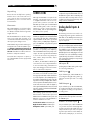
Unpacking
Remove the unit carefully from its packing.
Find the remote control and other acces-
sories. Save the box as it will protect the
RSX-1058 if you move or need to return it
for maintenance.
Placement
Place the RSX-1058 on a solid, level surface
away from sunlight, heat, moisture, or vibra-
tion. Make sure that the shelf can support the
weight of the unit.
Place the RSX-1058 close to the other compo-
nents in your system and, if possible, on its
own shelf. This will make initial hookup, and
subsequent system changes easier.
The RSX-1058 can generate heat during nor-
mal operation. Do not block ventilation open-
ings. Allow a minimum of 10 cm or 4
inches of unobstructed space around
the unit. If installed in a cabinet, make sure
that there is adequate ventilation.
Don’t stack other components or objects on
top of the RSX-1058. Don’t let any liquid fall
into the unit.
CONNECTIONS
Although the RSX-1058’s rear panel looks
daunting, connecting the unit to your system
is straightforward. Each of the source com-
ponents in the system are connected to the
RSX-1058 inputs with a pair of standard RCA
cables for analog audio, a video connection
(Composite, S-Video, Component Video,
and/or HDMI), and an optional digital au-
dio cable (coax or optical).
NOTE: Surround formats like Dolby Digital
and DTS are digital formats and the RSX-1058
can only decode them when a digital input
signal is available. For this reason, you should
always connect your DVD player’s digital out-
puts to the RSX-1058, using either the optical
or coax inputs.
The outputs of RSX-1058 are sent to up to five
speakers or to optional power amplifier(s)
with standard RCA cables from preamp audio
outputs. The video signal from the RSX-1058
is sent to the TV monitor using Composite
video, S-Video, Component Video, and/or
HDMI connections.
In addition, the RSX-1058 has MULTI input
connections for a source component that does
its own surround decoding, remote IR sensor
inputs, and 12V trigger connections for remote
turn-on of other Rotel components.
NOTE: Do NOT plug any system component
into an AC source until all connections have
been properly made.Video cables should have
a 75 ohm impedance. The S/PDIF digital au-
dio interface standard also specifies a 75 ohm
impedance and all good digital cables adhere
to this requirement. Do NOT substitute conven-
tional audio interconnect cables for digital or
video signals. Standard audio interconnects will
pass these signals, but their limited bandwidth
reduce performance.
When making signal connections, connect
LEFT channels to LEFT channel jacks and
RIGHT channels to RIGHT channel jacks. All
RCA-type connections on the RSX-1058 fol-
low these standard color codes:
Left channel audio: white RCA jack
Right channel audio: red RCA jack
Composite video: yellow RCA jack
NOTE: Each source input must be properly
configured using the INPUT SETUP menu of
the OSD menu system. We recommend going
to this menu after connecting each source to
configure it as desired. See Input Setup of the
Setup section for information.
Analog Audio Inputs &
Outputs
The following connections are used for con-
necting analog audio signals to and from the
RSX-1058. See the Making Connections topic
for specific instructions on connecting each
type of component.
NOTE: Normally, the RSX-1058 converts an-
alog inputs to digital signals. All of the digital
processing is available including bass manage-
ment, digital crossovers, speaker level and delay
settings, and a number surround mode options.
Alternatively, there is an analog bypass surround
mode that routes 2-ch and Multi Input analog
signals directly to the Volume control and out-
puts, bypassing the digital processing entirely
for pure analog stereo.
CD Inputs i
A left/right pair of RCA analog audio inputs
for connecting a CD player.
TAPE Inputs
A pair of RCA inputs, labeled TAPE IN, for
connecting the left/right analog audio sig-
nals from an audio tape deck or recording
device.
TAPE Outputs
A pair of RCA inputs, labeled TAPE OUT,
for sending left/right line level analog au-
dio signals for recording on a tape deck or
recording device.
NOTE: These outputs should be connected to
the inputs of the same tape deck connected to
the TAPE IN inputs.
VIDEO 1–5 Audio Inputs
Five pair of RCA inputs, labeled VIDEO IN
1–5, provide connections for left/right ana-
log audio signals from five additional source
components. These inputs have correspond-
ing video inputs and are used for VCRs, sat-
ellite TV tuners, DVD players, etc. However,

17
English
they may also be used for additional audio
only components, simply by omitting the cor-
responding video connections.
VIDEO 1–2 Audio Outputs
Two pair of RCA jacks, labeled VIDEO OUT
1 & 2, provide connections for sending line
level left and right analog audio signals for
recording to a VCR.
These connections correspond to the VIDEO
IN 1–2 connections. Make sure that you are
consistent. If you hook up a particular VCR
to the VIDEO 1 inputs, hook up the VIDEO
1 outputs to the same VCR.
NOTE: There are no analog audio outputs for
VIDEO 3, 4 & 5. Therefore, in an elaborate
system, hook up all of the VCRs and recording
devices to VIDEO 1–2 and use VIDEO 3, 4 &
5 for playback only components.
NOTE: Video 1–2 can be used for audio-only
tape decks, simply omitting the corresponding
video connections.
MULTI Inputs
A set of RCA inputs accept up to 7.1 chan-
nels of analog signals from a DVD-A or SACD
player. There are inputs for FRONT L & R,
CENTER, SUB, REAR L & R, and CENTER
BACK (CB) 1 & 2.
These inputs bypass all digital processing in
the RSX-1058 and are routed directly to the
Volume control and outputs.
There are two subwoofer options for the MULTI
input. Normally, the .1 channel input is passed
through directly to the subwoofer output. An
optional bass redirect feature duplicates the
7 main channels, sums them, and sends this
mono signal through a 100 Hz analog low
filter to the subwoofer output. This provides
an unaltered analog bypass for the seven
main channels along with a subwoofer sig-
nal derived from those channels.
Speaker Outputs
The RSX-1058 has five built-in amplifiers,
two for the front (right and left), one for the
center channel, and two for the rear sur-
round speakers (right and left). There are five
pairs of binding post connections (one pair
for each speaker) which accept bare wire,
spade lugs, or banana plug connectors (in
some markets).
NOTE: The RSX-1058 has a speaker redirect
feature which allows you to use the front chan-
nel amplifiers to drive center back speakers
or remote Zone 2 speakers when a separate
power amplifier is used for the front speak-
ers. This feature is configured in the Default
Setup menu.
Preamp Outputs
A group of ten RCA analog audio outputs
sends the RSX-1058’s line level output signals
to external amplifiers and powered subwoof-
ers. These outputs are variable level, ad-
justed by the RSX-1058 volume control. The
ten connectors provide output for: FRONT L
& R, CENTER 1 & 2, SURROUND (REAR) L
& R, CENTER BACK CB1 & CB2, and SUB-
WOOFER 1 & 2.
NOTE: Depending on your system configura-
tion, you may use some or all of these connec-
tions. For example, if you only have one center
channel, connect it to the CENTER 1 output. If
you only have one center back channel, con-
nect it to the CB1 output.
ZONE 2–4 Audio Outputs
Three pair of RCA inputs, labeled ZONE OUT,
sending analog audio signals to external am-
plifiers for a remote zones. These outputs can
be configured as either fixed or variable level
using the ZONE 2–4 SETUP menu.
NOTE: Only analog input signals are avail-
able at the Zone 2–4 outputs. Source compo-
nents connected to only the digital inputs are
not available in Zone 2–4.
To configure your system for Zone 2–4 op-
eration, connect the left and right Zone 2, 3
or 4 outputs on the RSX-1058 to the left and
right channel inputs of the amplifier power-
ing the remote speakers in the appropraite ,
using standard RCA audio cables.
Video Inputs & Outputs
These connections are used for connecting
video signals to and from the RSX-1058. See
the Making Connections section for specific
instructions for each type of component.
The RSX-1058 provides Composite, S-Video,
Component Video, and HDMI connections.
Composite video connections simplify system
configuration; however, S-Video connections
typically provide better picture quality. Com-
ponent Video or HDMI connections provide
the best signal quality and are required for
HDTV or progressive scanned DVD video.
NOTE: The HDMI digital connections are
compatible with DVI components with an ap-
propriate DVI-D cable adapter.
The RSX-1058 provides upscaling and down-
scaling for the various video formats. Com-
posite Video or S-Video video signals can
be upscaled to 480p/576p, 720p, 1080i
and 1080p on HDTV Component or HDMI
monitors by choosing the appropriate output
setting in the VIDEO/HDMI menu.
Also, HDMI or Component input video sig-
nals at 1080i or 720p can be downscaled
to 480p/576p for a HDTV monitor by choos-
ing this output setting in the VIDEO/HDMI
menu.
When the input is 1080p, it cannot be down-
scaled but is pass-through only and is not af-
fected by the output setting.
NOTE: The HDTV Component Video output
is subject to HDCP copy protection. It may not
display 720p or 1080i resolution when the
source signal incorporates copy protection.
Consider the following implications for your
system configuration:
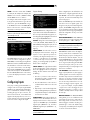
On Screen Display: The RSX-1058 OSD
system is available on the TV monitor, when
using Composite, S-Video, or Component
Video and HDMI connections from the
RSX-1058 outputs to the TV set. OSD menus
are available on all video monitors. But,
the OSD menu video resolution is available
only at 480i/576i for a Composite/S-Video
monitor, and 480p/576p only for a HDTV
monitor. When the monitor is connected by
Component Video only (not together with
HDMI), the OSD is available at 480i/576i.
NOTE: With the RSX-1058, the TV monitor
cannot display the video signal and the OSD
menus at the same time. When the main OSD
setup menus are activated, the video input is
interrupted and restored when the OSD menus
are cancelled. When the temporary OSD is
displayed on the the TV monitor in the case
of Composite or S-Video video input, it is not
related to the video output resolution.
Output Conversion: The RSX-1058 converts
Composite and S-Video signals to Component
Video signals for output to an NTSC or PAL

18
RSX-1058 Surround Sound Receiver
TV monitor. S-Video signals cannot be con-
verted to Composite outputs. For maximum
convenience, connect the RSX-1058 to the
TV monitor with Component Video or HDMI
Video connections.
NOTE: When you have changed the output
resolution in the VIDEO/HDMI menu during
operation, restart by switching power OFF and
ON again, to stabilize the picture image in the
new resolution setup.
Many digital HDTV monitors adjust scan
rates and other video parameters depend-
ing on the type of input connection. You may
wish to make multiple connections between
the RSX-1058 and the TV monitor, switch-
ing inputs on the TV to take advantage of
these features.
NOTE: Do not connect HDMI and Compo-
nent Video outputs to a monitor simultane-
ously, as the two video image signals may
affect each other.
VIDEO 1–3
Composite Video Inputs
Three inputs accepts standard Composite
video signals from source components using
standard 75 ohm RCA video cables.
VIDEO 1–2
Composite Video Outputs
Two RCA jacks, labeled COMPOSITE OUT
1 & 2, provide connections for sending Com-
posite video signals for recording on a VCR
or other recording device. These connections
correspond to the VIDEO IN 1–3 connec-
tions. Make sure that you are consistent. If
you hook up a particular VCR to the VIDEO
1 inputs, hook up the VIDEO 1 output to the
same VCR.
NOTE: The RSX-1058 cannot convert S-Video
or Component Video to Composite Video. There-
fore, only signals from the Composite Video
inputs are available at these outputs.
VIDEO 1–3 S-Video Inputs
Three inputs, labeled S-VIDEO IN 1–3 accept
S-Video signals from source components.
VIDEO 1–2 S-Video Outputs
Two S-VIDEO jacks, labeled S-VIDEO OUT 1
& 2, provide connections for sending S-Vid-
eo signals for recording on a VCR or other
recording device.
These connections correspond to the VIDEO
IN 1–3 connections. Make sure that you are
consistent. If you hook up a particular VCR
to the VIDEO 1 inputs, hook up the VIDEO
1 output to the same VCR.
NOTE: The RSX-1058 cannot convert Com-
posite video or Component Video signals to
S-Video. Only signals received at the S-Video
inputs are available at these outputs.
VIDEO 1–3
Component Video Inputs
Component Video connections split the vid-
eo into three signals – luminance (Y) and
chrominance (PB and PR) signals, allowing
delivery of a reference quality picture with
high definition signals. Component Video
connections should be used for progressive
scan DVD players and high-definition televi-
sion receivers. Each of these signals is car-
ried by a separate 75 ohm video cable with
RCA connectors.
Three sets of inputs, labeled COMPONENT
VIDEO IN 1–3 accept Component video sig-
nals from source components.
NOTE: When using a progressive scan or
1080i HDTV video signal from the Component
Video inputs, the TV monitor cannot display
the video signal and the OSD menus at the
same time. When the main OSD setup menus
are displayed, the progressive video signal is
interrupted and restored when the OSD menus
are cancelled. The temporary OSD informa-
tion displays (such as volume setting, etc.) are
not displayed.
VIDEO 1–4
HDMI Inputs
HDMI inputs provide various digital video con-
nections for use with components that have
either HDMI outputs or DVI-D outputs (with
an appropriate DVI-HDMI adapter). HDMI
connections carry video signals in all formats
including progressive scan up to 1080p. The
implementation of HDMI supports audio sig-
nals, or a separate audio connection from
an HDMI component.
Four inputs, labeled HDMI VIDEO IN 1–4 ac-
cept signals from source components.
NOTE: When using HDMI connections, the TV
monitor can display the OSD menus and can
also display video from Composite, S-Video, or
Component Video sources, as the RSX-1058 is
capable of upscaling these signals.
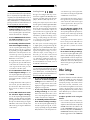
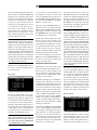
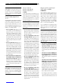
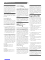
TV Monitor Outputs
The TV MONITOR outputs of the RSX-1058
send the video signal to your TV monitor.
Four types of video output connections are
provided – RCA Composite video, S-Video,
Component Video, and HDMI digital.
The Composite Video output sends all interlace
video inputs to the TV monitor; the S-Video
output also sends all interlace video inputs to
the TV. The HDMI output sends all format video
inputs to the TV; the Component Video output
also sends all format source inputs to the TV.
Therefore, HDMI and Component Video are
the most convenient type of connection. It is
always possible to use Component or HDMI
as a single output connection, because the
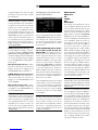
RSX-1058 includes upconversion and scaling
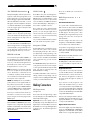
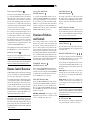
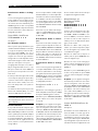
for all video inputs. See the VIDEO INPUT/
OUPUT FORMATS list, on this page.
NOTE: When you have changed the output
resolution in the VIDEO/HDMI menu during
operation, restart by switching power OFF and
ON again, to stabilize the picture image in the
new resolution setup.
● ● ● ● ● ● ● ●
● ● ● ● ● ● ● ●
● ● ● ● ● ● ●
● ● ● ● ● ● ●
● ● ● ● ● ● ●
● ● ● ● ● ● ● ●
● ● ● ● ● ● ●
● ● ● ● ● ● ●
● ● ● ● ● ● ●
●
*
* *
* *
* *
* *
* *
* *
* *
* *
* *
Video Input/Output formats

19
English
NOTE: HDTV Component Video output is
subject to HDCP copy protection. It may not
display 720p or 1080i resolution when the
source signal incorporates copy protection.
However, when Video Out is set to 480p/576p
in the VIDEO/HDMI menu, all sources will be
available. Component Video output is not avail-
able for 480i/576i images.
NOTE: Do not connect HDMI and Compo-
nent Video outputs to a monitor simultane-
ously, as the two video image signals may
affect each other.
HDMI connections:
• The RSX-1058 uses the HDMI Ver. 1.1
standard. TV monitors with HDMI inputs
should be compatible with this version.
• The video signal sent to the TV through the
HDMI connection will not be displayed
properly unless all HDMI components in
the system, including the TV monitor, are
compatible with the HDCP copy protec-
tion standard.
• Only audio signals passed-through directly
from the source component are sent to the
TV set through the HDMI connection. To
send decoded audio from the RSX-1058
to the TV, you must select ‘TV mode’ in
the VIDEO/HDMI menu.
• TV monitors with DVI-D connections can
usually be connected to the HDMI out-
put of the RSX-1058 with the use of an
appropriate 24-pin DVI-HMDI adaptor.
However, there are occasionally some in-
compatibilities with older DVI-D equipped
monitors.
• Use the scaler setting of the RSX-1058
‘VIDEO OUT FORMAT’ in the VIDEO/
HDMI menu to match the natiive resolu-
tion of the TV monitor.
• In general, HDMI is the optimum connec-
tion for digital high-definition monitors
such as LCD, plasma, or DLP monitors.
NOTE: Do not connect HDMI and Compo-
nent Video outputs to a monitor simultane-
ously, as the two video image signals may
affect each other.
ZONE OUT Video Outputs
The ZONE OUT Video outputs of the RSX-1058
send a Composite video signals to TV moni-
tors in Zone 2, 3 & 4.
NOTE: Only Composite video input signals are
available at the Zone 2, 3 & 4 video outputs.
Digital Audio
Input & Outputs
The RSX-1058 provides digital connections
which may be used in place of, or in addition
to, the analog audio input and output con-
nections described in the previous sections.
These connections include seven digital inputs
and also an HDMI Audio digital input. and
two digital outputs (for recording),
These digital connections can be used with
any source component that supplies a digi-
tal signal, such as a DVD player, CD player,
or satellite TV tuner.
NOTE: With a digital connection, the RSX-1058
will be used to decode the signal, rather than
the source component’s internal decoders. In
general, you must use digital connections for a
DVD player or other component that supplies
a Dolby Digital or DTS signal; otherwise the
RSX-1058 will not decode these formats.
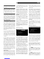
Digital Inputs
The RSX-1058 accepts digital inputs from
source components such as CD players, sat-
ellite TV tuners, and DVD players. The built-
in digital processor senses and adjusts to the
correct sampling rates.
There are seven digital inputs on the rear
panel, three coaxial and four optical, as well
as HDMI Audio input. These digital inputs
can be assigned to any of the input sources
using the INPUT SETUP screen during the
setup process. For example, you can assign
the COAXIAL 1 digital input connector to the
VIDEO 1 source and the OPTICAL 2 digital
input to the VIDEO 3 source. By default, the
source input buttons are factory configured
to select the following inputs:
CD: Digital Coaxial 2
Tuner: Analog (built-in)
Tape: Digital Coaxial 3
Video 1: HDMI Audio (HDMI 1)
Video 2: HDMI Audio (HDMI 2)
Video 3: Digital Optical 1
Video 4: Digital Optical 2
Video 5: Digital Coaxial 1
NOTE: When using digital connections, you
should also make the analog audio input con-
nections described previously. The analog con-
nection is necessary to record to an analog
recorder in some circumstances or for ZONE
2, 3 & 4 operation.
Digital Outputs
The RSX-1058 has two digital outputs (one
coaxial and one optical) to send the digital
signal from any of the digital inputs to a dig-
ital recorder or outboard digital processor.
When a digital input source signal is selected
for listening, that signal is automatically sent
to both digital outputs for recording.
NOTE: Only digital signals from source com-
ponents are available at these outputs. Analog
signals cannot be converted and are not avail-
able at the digital outputs.
Other Connections
AC Input
Your RSX-1058 is configured at the factory
for the proper AC line voltage in the country
where you purchased it (USA: 120 volts/60Hz
AC or CE: 230 volts /50 Hz AC ). The AC
line configuration is noted on a decal on the
back of your unit.
Plug the supplied cord into the AC INPUT re-
ceptacle on the back of the unit.
NOTE: Memorized settings and video labels
are preserved indefinitely, even if the RSX-1058
is disconnected from AC power.
Master Power Switch
The large rocker switch on the rear panel is
a master power switch. When it is in the OFF
position, power to the unit is completely off.
When it is in the ON position, the front-panel
STANDBY and remote control ON/OFF but-
tons can be used to activate the unit or put it
into standby mode.
NOTE: After all connections are completed,
the rear panel master power switch should
be put in the ON position and usually left in
that position.

20
RSX-1058 Surround Sound Receiver
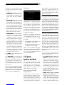
12V TRIGGER Connections
Many Rotel amplifiers offer the option of turn-
ing them on and off using assignable 12 volt
trigger signals. These six connections provide
this 12 volt trigger signal from the RSX-1058.
When the RSX-1058 is activated, a 12 volt
DC signal is sent to the amplifiers to turn them
on. When the RSX-1058 is put in STANDBY
mode, the trigger signal is interrupted and
the amplifiers turn off.
NOTE: The 12V Trigger outputs can be as-
signed to turn on only when specific input
sources are activated. See the Input Setup and
Zone 2–4 Setup menus in the Setup section of
this manual for details.
To use the remote turn on feature, connect
one of the RSX-1058’s 12V TRIG OUT jacks
which is assigned to the 12 volt trigger input
of a Rotel amplifier, using a cable with mono
3.5 mm mini-plugs on both ends. The +12 V
DC signal appears at the “tip” connector.
REM IN Jacks
Four 3.5 mm mini-jacks (labeled ZONE 2, 3
& 4, and EXT) receive command codes from
an industry-standard infrared receiver (Xan-
tech, etc.), used when the IR signals from a
hand held remote control cannot reach the
front-panel IR sensor or zone rooms.
EXT: The EXT jack is used with an outboard
IR receiver to duplicate the front-panel IR
sensor. This feature is useful when the unit
is installed in a cabinet and the front-panel
sensor is blocked or when IR signals need to
be relayed to other components.
ZONE: The ZONE jacks are used with IR re-
peater systems to receive signals from IR con-
trol systems in remote locations. For example,
remote signals sent to the ZONE 2 REM IN
control the ZONE 2 features of the RSX-1058
and can be relayed to other components.
Consult your authorized Rotel dealer for
information on external receivers and the
proper wiring of 3.5 mm mini-plugs to fit the
REM IN jacks.
NOTE: The IR signals from the EXT REMOTE
IN and ZONE 2–4 REMOTE IN jacks can be
relayed to source components using external
IR emitters or hard-wired connections from the
IR OUT jacks. See the following section for ad-
ditional information.
IR OUT Jacks
The IR OUT 1 & 2 jacks send IR signals re-
ceived at the ZONE 2–4 REM IN or the EXT
REM IN jacks to an infrared blaster or emit-
ter placed in front of a source component’s IR
sensor. In addition, the IR OUT can be hard-
wired to Rotel CD players, DVD players, or
tuners with a compatible connector.
These outputs are used to allow IR signals
from Zones 2–4 to be sent to the source com-
ponents, or to pass along IR signals from a
remote in the main room when the sensors
on the source components are blocked by
installation in a cabinet.
See your authorized Rotel dealer for informa-
tion on IR emitters and repeater systems.
Computer I/O
The RSX-1058 can be operated from a com-
puter with audio system control software
from third-party developers. This control is
accomplished by sending operating codes
from the computer via a hard-wired RS-232
serial connection. In addition, the RSX-1058
can be updated using special software
from Rotel.
The COMPUTER I/O input provides the nec-
essary network connections on the rear pan-
el. It accepts standard RJ-45 8-pin modular
plugs, such as those commonly used in 10-
BaseT UTP Ethernet cabling.
For additional information on the connections,
cabling, software, and operating codes for
computer control or updating of the RSX-1058,
contact your authorized Rotel dealer.
Making Connections
CD Player
See Figure 10
Connect the left and right analog outputs
from the CD player to the AUDIO IN jacks
labeled CD (left and right).
Optional: Connect the digital output of
the CD player to any of the Optical or Coax
digital inputs on the RSX-1058. Use the IN-
PUT SETUP screen to assign that digital input
to the CD source. The default assignment is
COAXIAL 2.
There are no default video connections for
a CD Player.
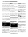
DVD Player
See Figure 6
Standard Definition TVs:
In a system with a standard definition TV,
DVD connections can be made to the VIDEO
1, 2, 3, 4 or 5 inputs. You may wish to use
assigned Video Inputs with interlace picture
for DVD players. The video picture is then
available by the assigned Video Inputs. The
analog audio is the same as the input la-
belled terminals.
The video setting in each video source is by
assignment, so the INPUT labels of VIDEO 1-5
do not relate to video terminal numbers.
It is possible to assign any type of video ter-
minals, from the available three Composite
Video, three S-Video, three Component Vid-
eo and four HDMI.
If the monitor used is SDTV, an interlace source
(480i/576i) should be used.
NOTE: If you plan to distribute video from
the DVD player to a TV monitor in Zone 2, 3
or 4, you must make a composite video con-
nection.
High Definition TVs:
It is possible to connect any video input for
use with an HDTV monitor, as the RSX-1058
has a built-in video converter and scaler in-
side. However, the higher the resolution of
the input signal, the higher the quality of
the picture.
If you intend to use the progressive scan
feature with an HDTV monitor, you should
use Component Video and/or HDMI video
connections from the DVD player. If the DVD
player has a DVI-D output, this can usually be
connected to the HDMI input on the RSX-1058
using a DVI-HDMI adapter.
Connect a set of Component Video cables or
an HDMI cable from the DVD player to the
appropriate VIDEO 1, 2 or 3 input or HDMI
1–4 input on the RSX-1058.
Digital Audio connections:
Connect the digital output of the DVD player
to any one of the OPTICAL IN or COAXIAL IN
digital inputs on the RSX-1058. Use the INPUT
SETUP screen to assign that digital input to
La page est en cours de chargement...
La page est en cours de chargement...
La page est en cours de chargement...
La page est en cours de chargement...
La page est en cours de chargement...
La page est en cours de chargement...
La page est en cours de chargement...
La page est en cours de chargement...
La page est en cours de chargement...
La page est en cours de chargement...
La page est en cours de chargement...
La page est en cours de chargement...
La page est en cours de chargement...
La page est en cours de chargement...
La page est en cours de chargement...
La page est en cours de chargement...
La page est en cours de chargement...
La page est en cours de chargement...
La page est en cours de chargement...
La page est en cours de chargement...
La page est en cours de chargement...
La page est en cours de chargement...
La page est en cours de chargement...
La page est en cours de chargement...
La page est en cours de chargement...
La page est en cours de chargement...
La page est en cours de chargement...
La page est en cours de chargement...
La page est en cours de chargement...
La page est en cours de chargement...
La page est en cours de chargement...
La page est en cours de chargement...
La page est en cours de chargement...
La page est en cours de chargement...
La page est en cours de chargement...
La page est en cours de chargement...
La page est en cours de chargement...
La page est en cours de chargement...
La page est en cours de chargement...
La page est en cours de chargement...
La page est en cours de chargement...
La page est en cours de chargement...
La page est en cours de chargement...
La page est en cours de chargement...
La page est en cours de chargement...
La page est en cours de chargement...
La page est en cours de chargement...
La page est en cours de chargement...
La page est en cours de chargement...
La page est en cours de chargement...
La page est en cours de chargement...
La page est en cours de chargement...
La page est en cours de chargement...
La page est en cours de chargement...
La page est en cours de chargement...
La page est en cours de chargement...
La page est en cours de chargement...
La page est en cours de chargement...
La page est en cours de chargement...
La page est en cours de chargement...
La page est en cours de chargement...
La page est en cours de chargement...
La page est en cours de chargement...
La page est en cours de chargement...
La page est en cours de chargement...
La page est en cours de chargement...
La page est en cours de chargement...
La page est en cours de chargement...
La page est en cours de chargement...
La page est en cours de chargement...
La page est en cours de chargement...
La page est en cours de chargement...
-
 1
1
-
 2
2
-
 3
3
-
 4
4
-
 5
5
-
 6
6
-
 7
7
-
 8
8
-
 9
9
-
 10
10
-
 11
11
-
 12
12
-
 13
13
-
 14
14
-
 15
15
-
 16
16
-
 17
17
-
 18
18
-
 19
19
-
 20
20
-
 21
21
-
 22
22
-
 23
23
-
 24
24
-
 25
25
-
 26
26
-
 27
27
-
 28
28
-
 29
29
-
 30
30
-
 31
31
-
 32
32
-
 33
33
-
 34
34
-
 35
35
-
 36
36
-
 37
37
-
 38
38
-
 39
39
-
 40
40
-
 41
41
-
 42
42
-
 43
43
-
 44
44
-
 45
45
-
 46
46
-
 47
47
-
 48
48
-
 49
49
-
 50
50
-
 51
51
-
 52
52
-
 53
53
-
 54
54
-
 55
55
-
 56
56
-
 57
57
-
 58
58
-
 59
59
-
 60
60
-
 61
61
-
 62
62
-
 63
63
-
 64
64
-
 65
65
-
 66
66
-
 67
67
-
 68
68
-
 69
69
-
 70
70
-
 71
71
-
 72
72
-
 73
73
-
 74
74
-
 75
75
-
 76
76
-
 77
77
-
 78
78
-
 79
79
-
 80
80
-
 81
81
-
 82
82
-
 83
83
-
 84
84
-
 85
85
-
 86
86
-
 87
87
-
 88
88
-
 89
89
-
 90
90
-
 91
91
-
 92
92


Rotel RSX-1058 Le manuel du propriétaire
- Taper
- Le manuel du propriétaire
dans d''autres langues
- English: Rotel RSX-1058 Owner's manual
Documents connexes
-
Rotel RSX-972 Manuel utilisateur
-
-
-
-
-
-
-
-