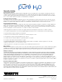
Watts Pure H20-DWRO300 Guide d'installation
- Taper
- Guide d'installation

Refer to enclosed warranty for operating parameters
to ensure proper use with your water supply.
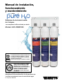
Installation, Operation and
Maintenance Manual
3-Stage Reverse Osmosis System
With Push-Button Filter Replacement
Model: H2O-DWRO300
System tested and certified by WQA against
NSF/ANSI Standards 42, 58, and NSF/ANSI/CAN
372 for Lead Free Compliance. For specific
performance and reduction claims verified
and substantiated through test data see the
performance data sheet.
P/N 88005233
WARNING
!
Please read carefully before proceeding with
installation. Your failure to follow any attached
instructions or operating parameters may lead to
the product’s failure.
Keep this Manual for future reference.

Page 2
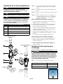
Overview
Thank you for your purchase of a state of the art Pure H2O
Reverse Osmosis (RO) water treatment system. Water quality
concerns are becoming more of a focus for the public. You
may have heard about contaminants in the drinking water
such as Arsenic, Chromium, Cryptosporidium or Giardia.
There may also be some local water issues such as high levels
of Lead and Copper. This Pure H2O water treatment system
has been designed to provide you with high quality drinking
water for years to come. The following is a brief overview of
the system.
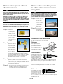
Your Reverse Osmosis System:
Osmosis is the process of water passing through a semi-
permeable membrane in order to balance the concentration of
contaminants on each side of the membrane. A semi-permeable
membrane is a barrier that will pass only certain particles like
clean drinking water, but not other particles like arsenic and lead.
Reverse osmosis uses a semi-permeable membrane; however,
by applying pressure across the membrane, it concentrates
contaminants (like a strainer) on one side of the membrane,
producing crystal clear water on the other. This is why RO
systems produce both clean drinking water and rinse water that
is flushed from the system. This reverse osmosis system also
utilizes carbon block filtration technology, and can therefore
provide a higher quality drinking water than carbon filtration
systems alone.
Your system is a three stage Reverse Osmosis which is based
upon separate treatment segments within the one complete
water filtration system. These stages are as follows:
WARNING
!
Do not use with water that is microbiologically unsafe or of
unknown quality without adequate disinfection before or after
the system.
If you are unsure about installing your Watts® water filter, contact
a Watts representative or consult a professional plumber.
IMPORTANT
CAUTION
!
NOTICE
Stage 1 – Carbon Block Filter, recommended change
every 6 months.
The first stage contains a 5 micron carbon block filter. This helps
ensure that chlorine and other materials that cause bad taste
and odor are greatly reduced. It is independently tested and
verified to trap matter like dirt, silt, and rust.
Stage 2- Reverse Osmosis Membrane, recommended
change every 2-5 years.
The second stage is the heart of the reverse osmosis system,
the 50GPD (Gallons Per Day) RO membrane. This independently
tested and verified semi-permeable membrane will effectively
reduce TDS, Sodium and a wide range of contaminants such
as Chromium, Arsenic, Copper, and Lead, as well as Cysts,
such as Giardia and Cryptosporidium. Because the process of
extracting this high quality drinking water takes time, your RO
water treatment system is equipped with a storage tank.
Stage 3- Granular Activated Carbon filter, recommended
change every 12 months.
The third stage is a Granular activated carbon (GAC) filter.
This filter is used after the water storage tank, as a final
polishing filter to the product water. There is an average of
4 gallons of reject water for every 1 gallon of product water
produced. That is why the life of the GAC filter is extended to
12 months vs the 6 months Carbon block.
Note: Filter and Membrane life may vary based upon local water
conditions and/or use patterns.
System Maintenance
It is important to change filters at the recommended interval
indicated in this manual. Many contaminants are not detectable
by taste. In addition, other bad tastes and odors may become
apparent over time if filters are not replaced.
It is important to change out your filters at the recommended
intervals as indicated in this system manual. When replacing the
filter elements, pay special attention to any cleaning instructions.
Should you have any further questions please call our retail
customer service at (888) 321-0500.
Failure to install the system correctly voids the warranty.
Handle all components of the system with care. Do not drop,
drag or turn components upside down.
Be sure the floor under the water filter system is clean, level
and strong enough to support the unit.
Discard small parts remaining after the installation.

Page 3
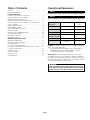
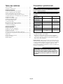
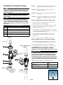
Operational Parameters
NOTICE
Installation must comply with state and local plumbing regulations.
Operating
Temperatures: Maximum 100°F (37.8°C) Minimum 40°F
(4.4°C)
Operating Pressure: Maximum 100 psi (690 kPa) Minimum 35 psi
(341 kPa)
pH Parameters: Maximum 11 Minimum 2
Iron: Maximum 0.2 ppm
TDS
(Total Dissolved Solids) < 1800 ppm
Turbidity < 5 NTU
Hardness Maximum 10 Grains
Per Gallon *
Hardness: Recommended hardness not to exceed 10 grains per
gallon, or 170 parts per million.
* System will operate with hardness over 10 grains but the
membrane life may be shortened. Addition of a water
softener may lengthen the membrane life.
Water Pressure: The operating water pressure in your home
should be tested over a 24 hour period to attain the maximum
pressure. If the incoming water pressure is above 100 psi then a
water pressure regulator is required. A booster pump is needed
for incoming water pressure under 35psi.
NOTICE
Table of Contents
Overview ........................................2
Operational Parameters.............................3
Installation and Startup
Contents of Reverse Osmosis System..................4
Recommended Tools For Installation ...................4
Plumbing Diagram and Parts List......................5
Drill a Hole for the Reverse Osmosis Faucet..............6
How to use Quick Connect Fittings on Your RO System ....6
Faucet Installation .................................7
Adapt-a-Valve Installation ...........................8
Drain Saddle Installation ............................8
Drain Saddle Tube Connection .......................9
Tube Connections .................................9
Reverse Osmosis Module Mounting ..................10
Tank Ball Valve Installation ..........................10
Blue Tube Connection .............................10
Start up Instructions ..............................10
Maintenance and Troubleshooting
Membrane Replacement ..........................11
Changing The Filter Cartridges ......................11
Annual Sanitization ...............................12
Check Air Pressure in the Tank ......................13
Procedure for Extended Non-Use (More than 2 months) ...13
Performance Data Sheet ...........................14
Troubleshooting .................................15
Arsenic Fact Sheet ...............................15
Service Record ..................................16
Limited Warranty .................................18
Copper Tube: Reverse Osmosis water should not be run through
copper tube as the purity of the water will leach copper causing
an undesired taste in water and pin holes may form in the tube.
System is intended to be installed using the cold water supply only.
WARNING
!

Page 4
If any of the items are missing please contact retail customer
service at (888) 321-0500 prior to installing.
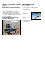
Contents of the Reverse Osmosis
(RO) System
Please make sure all of the items listed below are contained in the
box. If any of the items are missing please contact retail customer
service at (888) 321-0500 prior to installing.
• Tank
• Module - Carbon Block , Reverse Osmosis Membrane,
Granular Activated Carbon Filters (attached to filter head)
• Part bag - Water line tubing, Drain saddle, Adapt-a-valve with
brass adapters, drain saddle, tank ball valve, mounting screws
and PTFE thread seal tape
• Faucet with all assembly parts
Recommended Tools
For Installation
• 1¼" Diamond Tipped Hole Saw bit for faucet opening
(Counter Tops/Porcelain and Stainless Sinks)
• 1¼" adjustable wrench
• Phillips bit for electric drill
• ½" open end wrench
• Needle nose pliers
• 5⁄8" open end wrench
• Adjustable pliers
• Electric drill
• Sharp knife or tube cutter
• 1⁄8" diamond tip bit, pilot hole
• Phillips screw driver
• ¼" drill bit for drain saddle hole

Page 5
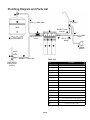
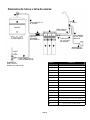
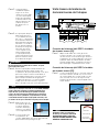
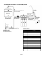
Plumbing Diagram and Parts List
1
9
5
13
3
11
7
15
2
10
10
6
14
4
12
8
Parts List
Item Description
1Filter Module
2Automatic Shut off Valve
3Storage Tank - 3 Gallons
4Adapt-a-Valve
5Faucet - Standard A/G Chrome
6Tank Valve - ¼" FNPT x ¼" C
7Drain Saddle - 3⁄8 QC - Kit
8Tank Stand
9¼" Green Tubing
10 ¼" Blue Tubing
11 3⁄8" Black Tubing - 3ft. X 1
12 ¼" Red Tubing
13 Carbon Block Filter (H2O-F12)
14 Reverse Osmosis Membrane Filter (H2O-F16)
15 Granular Activated Carbon Filter (H2O-F17)
16 Union Fitting - ¼" QC X ¼" QC
COLD WATER
ANGLE-STOP
SUPPLY
ADAPT
-A-
VALVE
GREEN ¼" TUBE FEED
TANK
AUTO-SHUT OFF
VALVE
BLUE ¼" TUBE TANK
BLUE ¼" TUBE
FAUCET
FAUCET
BLACK 3⁄8" TUBE
DRAIN
RED ¼" TUBE
BRINE
DRAIN
SADDLE
16

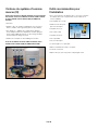
Page 6
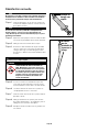
Step 1 - Determine desired
location for the
faucet on your sink
and place a piece of
masking tape over
where the hole is to
be drilled. Mark the
center of the hole on
the tape.
Step 2 - Using a variable
speed drill set on the
slowest speed, drill
a 1⁄8" pilot hole with
the 1⁄8th in diamond
drill bit through both
porcelain and metal
casing of sink at the
marked center of
the desired location.
Use lubricating oil or
liquid soap to keep the drill bit cool (If drill bit gets hot
it may cause the porcelain to crack or chip).
Step 3 - Using a 1¼" diamond tip hole saw, proceed to drill
the large hole. Keep drill speed on the slowest speed
and use lubricating oil or liquid soap to keep the hole
saw cool during cutting.
Step 4 - After drilling, remove all sharp edges and make
sure the surroundings of the sink are cooled before
mounting the faucet.
NOTICE
NOTICE
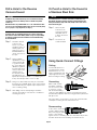
Drill a Hole for the Reverse
Osmosis Faucet
For Marble and granite Counter-tops, we recommend contacting
a qualified contractor for drilling a hole in a marble and granite
counter-top.
Note: Most sinks are predrilled with 1½" or 1¼" diameter hole that
you can use for your Drinking Water faucet. (If you are already using
it for a sprayer or soap dispenser, see Step 1).
Porcelain sinks are extremely hard and can crack or chip easily.
Use extreme caution when drilling. Watts accepts no responsibility
for damage resulting from the installation of faucet. Diamond tip
bit recommended.
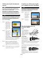
Cut the tube square. It is
essential that the outside
diameter be free of score
marks, and that burrs and
sharp edges be removed
before inserting into fitting.
Using Quick-Connect Fittings
Cutting
Make certain to push
the tubing completely
into the connector until
it comes into contact
with the internal tubing
stop. The collet (gripper) has stainless steel teeth which hold
the tube firmly in position while the O-ring provides a permanent
leak proof seal.
Pull on the tube to check that it is secure. The system must be
tested prior to leaving the site and/or before use.
Connecting
To disconnect, ensure the
system is depressurized
before removing the tube.
Push in collet squarely
against the face of the fitting. With the collet held in this position,
the tube can be removed. The fitting can then be reused.
Disconnecting
NOTICE
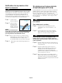
Or Punch a Hole for the Faucet in
a Stainless Steel Sink
If mounting faucet to a Stainless Steel Sink you will need a 1¼"
Hole Punch. The faucet opening should be centered between the
back splash and the edge of the sink, ideally on the same side as
the vertical drain pipe.
Step 1 - Drill a 1¼" pilot
hole. Use a 1¼"
Hole Punch and an
adjustable wrench
to punch the hole in
the sink.
Step 2 - The Faucet can
now be installed

Page 7
Step 1 - Remove water connector nut (Item 13) and blue
tubing (Item 14) from faucet.(Leave the plastic tube
insert and plastic delrin sleeve (Item 11 and 12) on
the blue tube).
Step 2 - Feed both the red (Item 3) and black tubing (Item 2)
through the pre-drilled hole in the sink/counter until
faucet is seated.
Step 3 - Under the sink - on to the threaded faucet stem (in
order ) first slide on the slotted metal washer (Item 6),
the plastic sleeve (Item 7) with the open end UP, the
plain washer (Item 8), the hex nut washer (Item 9) and
lastly secure with hex nut (Item 10).
Step 4 - Make sure the plastic delrin sleeve (Item 12) is on
the end of the blue tube; push the white plastic tube
insert (Item 11) into the end of blue tubing with the
delrin sleeve. Insert the blue tube (Item 14) into the
faucet stem and secure with water connector nut
with wrench (Item 13).
NOTICE
Secure the nut with a wrench but do not over tighten it.
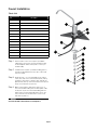
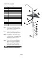
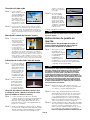
Faucet Installation
4
STEP 2
Step A – Remove nut (Item 13) and blue tubing (Item 14) from fau-
cet. (Leave the nut and plastic delrin sleeve (Item 11 & 12)
on the blue tube).
Step B – Feed both the red and black tubing through the pre-drilled
hole in the sink/counter until faucet is seated.
Step C – Under the sink - on to the threaded faucet stem in order
first slide on the slotted washer (Item 6), the white spacer
with the open end UP (Item 7), the hex nut washer (Item 8),
the slotted washer (Item 9) and lastly secure with nut (Item
10).
Step D – Make sure the plastic delrin sleeve (Item 12) is on the end
of the blue tube; push the white plastic insert (Item 11) into
the end of blue tubing with the delrin sleeve. Insert the blue
tube (Item 14) into the faucet stem and secure with nut
(Item 13).
DO NOT overtighten nut.
1. Faucet
2. Black Drain Tube (3/8” Black)
3. Red Tube 1/4”
4. Escutcheon Plate
5. Full Circle Rubber Gasket
6. Slotted Metal Washer
7. Plastic Sleeve
8. Plain Washer
9. Hex Nut Washer
10. Hex Nut
11. Plastic Tube Insert
12. White Plastic Delrin Sleeve
13. Water Connector Nut
14. Blue Tube 1/4”
Parts List
1
2
3
4
5
6
7
8
9
10
11
12
13
14
NOTICE
1
9
3
11
5
12
7
14
2
10
4
6
13
8
Parts List
Item Description
1Faucet
2Black Drain Tube (3⁄8" Black)
3Red Tube ¼"
4Escutcheon Plate
5Full Circle Rubber Gasket
6Slotted Metal Washer
7Plastic Sleeve
8Plain Washer
9Hex Nut Washer
10 Hex Nut
11 Plastic Tube Insert
12 White Plastic Delrin Sleeve
13 Water Connector Nut
14 Blue Tube ¼"

Page 8
If you have a garbage disposal, do not install the drain saddle near
it. Installation of the drain saddle must be either above the garbage
disposal, or if a second sink drain is available, install it above the
cross bar on the second drain. Installation of the drain saddle near
a garbage disposal may cause the drain line to plug.
Drain Saddle fits standard 1¼" – 1½" drain pipes
Drain Saddle Installation
CAUTION
!
1 Semicircle bracket with opening 2 Screws
1 Foam gasket 2 Nuts for screws
1 Semicircle bracket
Step 1 - Gather the pieces of the drain saddle
Step 1 - Turn off the cold water supply to the faucet by turning
the angle stop valve completely off.
Step 2 - Open cold water sink faucet to relieve pressure.
Step 3 - Disconnect the Faucet Line from the Cold water
supply.
Step 4 - Choose the configuration that fits your plumbing
needs and attach Adapt-a-ValveTM as instructed and
illustrated below.
Option 1: 3⁄8" Configuration (diagram to left)
a. Insert the White Rubber Washer (C) into the opening of Brass
Adapter with no washer (D)
b. Attach the female end of the Brass Adapter / White rubber
washer assembly (C&D) into the male end of the cold water
supply
c. Attach the female end of the plastic Adapt-a-Valve and
Black Collet (B) to the Brass Adapter/White Rubber Washer
Assembly (C&D)
d. Attach the female end of the Brass Adapter (A) to the male
end of the Plastic Adapt-a-Valve and black Collet (B)
e. Attach the faucet line to the Brass adapter (A)
Option 2: ½" Configuration (diagram to left)
a. Attach the Male end of Adapt-a-Valve and Black Collet (B) into
the Female end of the cold water supply
b. Attach the Male End of the Faucet Connection into the Female
end of the Adapt-a-Valve and Black Collet (B)
Parts List for Adapt-a-Valve
Item Description
ABrass Adapter with black washer
BPlastic Adapt-a-Valve and black collet
CWhite Rubber Washer
DBrass Adapter with no washer
NOTICE
NOTICE
NOTICE
Adapt-a-Valve Installation
Water supply line to the system must be from the cold water supply
line only. Hot water will severely damage your system.
Make sure that the black collet is installed into the ¼" opening on
the Adapt-a-Valve. Don’t forget to install the white compression
washer with the 3⁄8" configuration. The Brass Adapters do not need
to be tightened with a wrench, only finger tight.
Do not use PTFE thread seal tape with the Adapt-a-Valve™.
D
B
Line from
Cold Water
Supply
Faucet
Connection
Faucet Line
Cold
Water
Supply
C
B
A
D
B
Line from
Cold Water
Supply
Faucet
Connection
Faucet Line
Cold
Water
Supply
C
B
A
For ½" Configuration
(Option 2)
For 3⁄8" Configuration
(Option 1)

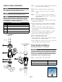
Page 9
Rear View of 3 stage Reverse
Osmosis System
Blue Tube Connection (From FAUCET To The
Reverse Osmosis (RO) Module)
Red Tube Connection (From FAUCET To The
Reverse Osmosis (RO) Module)
Do not over tighten the screws. It may crack the drain saddle.
CAUTION
!
Step 2 - The small square black
foam gasket with a circle
cut out of the middle
must be applied to the
inside of the drain saddle.
Remove sticky tape
backing and stick to the
drain saddle as shown.
Step 3 - The drain saddle must
be installed at least 1½"
above the nut of the P-Trap
elbow or cross bar from the
garbage disposal to insure
proper drainage. Using
the ¼" drill bit, drill into the
drain pipe at best available
location as specified above,
for drain saddle installation.
Take extreme caution to
only drill through one side of
the drain pipe.
Step 4 - Assemble the drain saddle around the drain pipe
and align drain saddle fitting opening with the hole
drilled in the previous step - you may use a small
screwdriver to feed through the drain saddle into the
drain pipe to aid with the alignment. Using a Phillips
screw driver tighten the drain saddle bolts evenly and
securely on both sides.
Step 5 - Measure the 3⁄8" black
tube from faucet to the
drain saddle on the drain
pipe and make a straight
cut to the correct length.
Step 6 - Connect the black tube to
the open quick connect
fitting on the drain saddle
by pushing the tube all the
way to the tube stop.
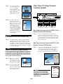
Step 1 - Locate the ¼" BLUE tube from the RO faucet.
Position the module as indicated in the “rear view”
picture. Insert the Blue Faucet tube into the ¼" quick
connect fitting (position A) located behind the GAC
Filter head making sure the tube is pushed in all the
way to the tube stop.
Step 1 - Locate the ¼" RED tube attached to the RO faucet.
Insert the end of the red tube into the ¼" quick
connect fitting attached to the red tubing that's
connected to the RO fitting (position B). Make sure
the tube is pushed in all the way to the tube stop.
NOTICE
The black 3⁄8" drain tube must be as SHORT and STRAIGHT as
possible to the drain saddle, making a downward slope from faucet
to drain saddle to allow for proper drainage. This is a gravity fed
line and if there is any bend or dip in the tube, the rinse water will
not flow into the drain properly. Water may back up and come out
the air gap hole in the back of the faucet.
A
B
CD
NOTICE
The Flow Restrictor is installed inside
of the red tube at the bent end. DO NOT
DISCONNECT OR CUT THE RED TUBING NEAR
THE BENT END AS IT WILL DAMAGE THE
FLOW RESTRICTOR.
CARBON BLOCK
H2O-F12
RO MEMBRANE
H2O-F16
GAC
H2O-F17
MOUNTING HOLES
GREEN TUBE-FEED
BLUE TUBE-TANK
RED TUBE-DRAIN
BLUE TUBE-FAUCET
Red Tube
Connection

Page 10
Step 1 - Turn on the incoming
cold water at the angle
stop valve and the
Adapt-a-Valve. Check
the system for leaks
and tighten any fittings
as necessary. (Check
frequently over the next 24 hours to ensure no leaks
are present).
Step 2 - Open the RO faucet and leave it open until water
begins to trickle out (this may take a few minutes and
the water will come out slowly).
Step 3 -
Close the RO faucet allowing the storage tank to fill with
water. It may take 3 to 6 hours to fill the tank completely
depending on the production capability of the
membrane, local water temperature and water pressure.
You will know that the water tank is filled when you no
longer hear the water flow sound from the tank.
Green Tube Connection
Step 1 - Insert the open end
of the green ¼" tube
from AUTO-SHUT OFF
VALVE into the Black
Collet of the Adapt-
a-Valve making sure
the tube is pushed in
all the way to the tube
stop. See Diagram on
the right
Reverse Osmosis Module Mounting
Step 1 - Determine best
location for the RO
module to be mounted
to allow for future
system maintenance.
Recommended best
location is 6" away
from the cabinet side
walls, and 10" from the
bottom of the cabinet for ease of installation and filter
change. The parts bag has 2 self tapping screws.
Using an electric drill with a Phillips bit, secure the
screws to the cabinet wall at locations that align with
the hole spacing on the module bracket.
Tank Ball Valve Installation
Step 1 - PTFE thread seal tape
must be applied in a
clockwise direction.
Wrap (7 to 12 turns)
around the male pipe
threads (MPT) on the
stainless steel fitting on
top of the tank.
Step 2 - Thread the
compression tank
ball valve (supplied in
the parts bag) onto
the stainless steel
connector on the tank.
NOTICE
NOTICE
Set the blue Tank valve knob in-line with the blue tube, this is the
“open” position.
If you have connected your RO system to a refrigerator / ice maker,
make sure the ice maker is off (do not allow water to flow to the
ice maker) until flushing (Step 4) is complete and the tank has
been allowed to fill completely. Connection from the RO to the ice
maker system should have an in-line valve installed before the ice
maker so it can easily be closed to prevent water flowing to the ice
maker during start up and periodic maintenance. Your storage tank
must be allowed to fill up fully in order for the ice maker system to
work properly.
Green Tube
Adapt-a-Valve
Start up Instructions
Congratulations! You have completed the
installation of your new water filtration system.
Please Follow the Startup Instructions.
ON
Step 4 - After the storage tank has filled open the RO Faucet
to flush the tank completely. You will know that the
tank is empty when the flow rate from the RO faucet
is down to a trickle. Repeat this step two more times.
The fourth tank can be used for drinking.
The flushing process should take about a day to complete.
Blue Tube Connection (From The Tank to
Shut off Valve and from Shut off Valve to the
Reverse Osmosis Module)
Step 1 - Position tank in desired location. Stand it upright
or lay it on its side (using the black plastic stand).
Measure the blue tube (marked “TANK”) from the
RO module to the tank and cut it to length leaving a
straight, square edge.
Step 2 - To the Blue tank tube (from position C) apply the
compression fitting to the cut edge side of the
tube. Make sure the
compression fitting
threaded opening is
facing the cut end of
the tube as shown in
the figure.
Step 3 - Insert the square edge
cut end of the blue
tube into the Tank
Valve opening. Using
clockwise rotation,
tighten the compression
fitting to the Tank Valve securing the tube in place.
See Diagram to right.

Page 11
NOTICE
NOTICE
Flushing of the tank 3 times is only necessary during the initial
startup and after replacing the reverse osmosis membrane.
Flush first tank after completing the annual maintenance.
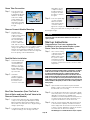
Step 1 - Place a towel under the RO module to catch any
excess water that may drip out from the filters during
the changeover.
Step 2 - To remove a filter cartridge: Push and hold the
button on the valve head above the filter. Twist filter
counter-clockwise for about 45 degree while pulling
downward (from the head). Release button and
discard old filter.
Step 3 - To install a filter cartridge: Remove the seal cap and
insert the cartridge into the filter head, push upward
and twist the filter clock-wise for about 45 degree
until you hear an audible “click” (the button does not
need to be pressed to install new filters)
Changing The Filter Cartridges
Your RO module is equipped with valve heads which will
automatically turn off the water supply to each filter when the
filter is released, thus you do not need to turn off the incoming
water supply at the Adapt-a-Valve. The RO faucet must be
off when filters are replaced. To make the removal of the filter
cartridges easier, the heads and cartridges may be swiveled up
to 90 degrees as shown in the pictures to the right.
To buy replacement part(s) please visit the retail store or their
website or contact Watts retail customer service at
(888) 321-0500
This reverse osmosis system contains a replaceable component
(the RO membrane) which is critical to the efficiency of the system.
Replacement of this reverse osmosis membrane should be with
H2O-F16 as defined by Pure H2O to assure the same efficiency
and contaminant reduction performance.
Annual Maintenance -
(Sanitization Recommended See page - 12)
• Carbon Block Filter............H2O-F12 (P/N # 88005217)
Capacity- 6 months / 2000 Gallons
• Granular Activated Carbon Filter...H2O-H17 (P/N # 88005219)
Capacity- 12 months / 2000 Gallons
• Carbon Block Filter............H2O-F12 (PN # 88005217)
Capacity- 6 months / 2000 Gallons
• Reverse Osmosis Membrane Filter...H2O-F16 (P/N 88005218)
Capacity- 2-5 years
Replace:Replace:
Replace:
Replace:
6 Month System Maintenance
TIP: This is a good time to check the air pressure in your storage
tank. For instructions please see page 13.
Membrane Replacement (2 - 5 Years)
Membranes have a life expectancy between 2 and 5 years,
depending on the incoming water conditions and the amount the RO
system is used. This reverse osmosis membrane is critical for effective
reduction of total dissolved solids (TDS). The product water should be
tested periodically to verify that the system is performing satisfactorily.
Normally, a membrane would be replaced during a semiannual or
annual filter change. However, if at any time you notice a reduction in
water production or an unpleasant taste in the reverse osmosis water,
it could be time to replace the membrane. Pure H2O recommends
replacing the membrane when TDS reduction falls below 75%.
A water sample may be sent to Pure H2O for a free diagnosis of
your membranes performance. To send a water sample, use 2 clean
containers and fill ½ cup of tap water in one container and 1/2 cup
of RO water in 2nd container. Clearly label each sample. Send the
samples to the address listed on the cover of this manual attention
“Water Samples”. Pure H2O will test the water and mail or call you
with the results.
Step 3-1
Step 3-3
Step 2
Step 3-2
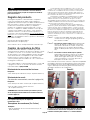
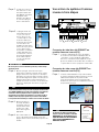
Product Registration
To Register your product, please visit www.watts.com/pureh2o
and select “Register Now”. Watts is concerned for the safety of
your personal information. Watts collects personal information
when you register with Watts. This information is stored in our
data base and we do not rent, sell, or share personal information
with other people or nonaffiliated companies. We will send you
certain types of communications such as direct mail, email, or
by telephone relating to our products or products that you have
purchased only with your prior permission. We limit access to
your personal information to those employees who will directly
provide you with services or products in order to do their jobs.
See our privacy policy at - http://www.watts.com/privacy.asp
See Terms of Use at - http://www.watts.com/terms.asp
Tubing not shown in above pictures. Do not remove the tubing
while changing the filter. Photographs for reference purposes
only. Your system may contain 1, 2, or 3 filter cartridges.
NOTICE

Page 12
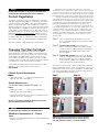
Point Hose
Ends Away
From Face
Dosing Syringe
With No Needle
NOTICE
NOTICE
Do not change your Granular Activated Carbon filter until the
sanitization has been completed. The Carbon Block and Reverse
Osmosis Membrane can be changed before the sanitization.
If you have connected your RO system to a refrigerator/ice maker,
make sure the connection has been turned off. Do not re-open the
connection until the sanitization process is complete.
Step 1 - Turn off the water supply to your RO system at the
Adapt-a-Valve and open the RO faucet to drain the
storage tank.
Step 2 - Locate the tube that runs between your filter module
and the storage tank and disconnect at both ends.
Step 3 - Drain any remaining water in the tube.
Step 4 - Hold both ends of the tube together with the ends
pointed away from your face. Using a dosing syringe
(see figure) slowly insert 1 teaspoon (5 mL) of
common household bleach into the tube.
Step 5 - While covering one end of the tube with your finger,
insert the other into the tank. Then insert the open
end into the filter module.
Step 6 - Turn the incoming water back on and let the system
fill for approximately 3 to 6 hours.
Step 7 - Turn off the incoming water and let the system sit for
1 minute.
Step 8 - Drain the system completely and then follow the
startup procedure - filling then draining three full
tanks of water.
Step 9 - Replace the Granular Activated Carbon filter once
complete.
Annual Sanitization
Do not use needle syringe
WARNING
!
DANGER
IF BLEACH GETS IN EYES: Hold eye open and rinse
slowly and gently with water for 15 - 20 minutes.
Remove contact lenses if present, after the first 5
minutes, then continue rinsing eye. Call a poison
control center or doctor for treatment advice.
!WARNING

Page 13
To Restart System:
Step 1 - Install the filters as shown in the 'Changing The Filter
Cartridges' section on page 11.
Step 2 - Turn on water supply to the system at the Adapt-a-
Valve. (Check frequently over the next 24 hours to
ensure no leaks are present).
Step 3 - Open the RO faucet and leave it open until water
begins to trickle out (it will come out slowly).
Step 4 - Close the RO faucet allowing the storage tank to fill
with water. It may take 3 to 6 hours to fill the tank
completely depending on the production capability
of the membrane, local water temperature and water
pressure.
Step 5 - After the Tank has filled, open the RO Faucet to flush
the tank completely. You will know that the tank
is empty when the flow rate from the RO faucet is
down to a trickle. The second tank can be used for
drinking.
NOTICE
NOTICE
NOTICE
Check air pressure only when tank is empty of water!
DO NOT FREEZE.
If you have connected your RO system to a refrigerator / ice maker,
make sure the ice maker is off (do not allow water to flow to the ice
maker) until the tank has been allowed to completely fill.
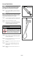
Step 1 - Turn off the incoming
water supply to the
RO.
Step 2 - Open the RO Faucet
and allow water to
drain from the tank
until it is completely
empty.
TIP:
When water from the RO faucet slows to a trickle, with the faucet still
in the open position, you may add air to the tank to purge any left
over water, this will ensure that the tank is completely empty.
Step 3 - Once all water in the tank is purged, check air
pressure using an air pressure gauge, it should read
between 5 - 7 PSI. (Digital air pressure gauge is
recommended)
Step 4 - Follow startup procedure on page 10.
Check air pressure in the storage tank when you notice a
decrease in available water from the RO system. Air can
be added with a bicycle pump using the schrader valve
that is located on the lower side of the tank behind the
blue plastic cap.
Turn off the water supply to your RO system at the Adapt-a-
Valve and open the RO faucet to drain the storage tank. Once
the storage tank is empty, remove all filter cartridges as shown
in the 'Changing The Filter Cartridges' section on page 11 (order
not important), place them into a sealed plastic bag and store in
your refrigerator.
Check Air Pressure in the Tank Procedure for Extended Non-Use
(More than 2 months)

Page 14
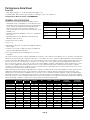
Performance Data Sheet
Pure H2O
-In U.S.-Watts Regulator Co., N. Andover, MA 01845 (Watts.com)
-In Canada-Watts, Water Technologies (Canada), Inc. Burlington, ON L7L 5H7 (Watts.ca)
3-Stage Reverse Osmosis System - H2O-DWRO300
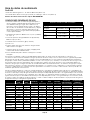
Recommended Replacement Parts and Change Interval
Note: Depending on incoming feed water conditions replacement time frame may vary.
Description Model / Part Number Change Time Frame
Carbon Block Filter H2O-F12 / 88005217 6 Months or 2000 Gallons
Reverse Osmosis
Membrane H2O-F16 / 88005218 2 to 5 years
Granular Activated Carbon
Filter H2O-F17 / 88005219 12 Months or 2000 Gallons
Avg. In. (mg/L) Avg. Eff. (mg/L) % Reduction pH Pressure Max Eff. mg/L Inf. challenge
concentration mg/L
Max Allowable
concentration mg/L
Arsenic (Pentavalent) 0.30 0.004 98.8% 7.77 50psi 0.009 0.30±10% 0.010 mg/L
Barium Reduction 9.7 0.19 98.0% 7.21 50psi 0.27 10.0±10% 2.0
Cadmium Reduction 0.03 0.0013 95.7% 7.61 50psi 0.0008 0.03±10% 0005
Chlorine 2.05 0.03 97% 7.0 - 8.0 N/A 2.4 2.0 mg/L ± 10% 2.2
Chromium (Hexavalent 0.29 0.002 95.8% 7.77 50psi 0.002 0.03±10% 0.1
Chromium (Trivalent) 0.33 0.004 98.9% 7.21 50psi 0.004 0.03±10% 0.1
Copper Reduction 3.1 0.0056 96.3% 7.61 50psi 0.062 3.0±10% 1.3
Cysts 92,000/ml 3/ml 99.97% 7.44 50psi 18 minimum 50,000/mL N/A
Fluoride Reduction 8.5 0.3 96.5% 7.24 50psi 0.3 8.0±10% 1.5
Lead Reduction 0.15 0.002 98.8% 7.39 50psi 0.005 0.15±10% 0.0107
Radium 226/228 25pCi/L 5pCi/L 98.0% 7.21 50psi 5pCi/L 25pCiL±10% 5pCiL
Selenium 0.11 <0.001 >99.1% 7.37 50psi <0.001 0.10±10% 0.05
TDS 727 13.7 98.1% 7.28 50psi 19.9 750±40mg/L 187
Turbidity 11 <0.1 NTU 99.1% 7.67 50psi <0.1 NTU 11±1mg/L 0.5NTU
Recovery - 24.7% Production Rate - 23.4 GPD Efficiency - 12.7%
GENERAL USE CONDITIONS
1. System to be used with municipal or well water sources
treated and tested on regular basis to insure bacteriological
safe quality. DO NOT use with water that is microbiologically
unsafe or unknown quality without adequate disinfection
before and after the system. Systems certified for cyst
reduction may be used on disinfected water that may contain
filterable cysts.
2. Operating Temperature: Maximum: 100°F (37.7°C) Minimum
40°F (4.4°C)
3. Operating Water Pressure: Maximum 100-psi (690 kPa)
Minimum: 35 psi (341 kPa)
4. Rated service flow: 0.5 GPM
5. pH 2 to 11
6. Maximum Iron present in incoming water supply must be less
than 0.2 ppm.
7. Hardness of more than 10 grains per gallon (170 ppm) may
reduce RO membrane life expectancy.
8. Recommend TDS (Total Dissolved Solids) not to exceed
1800 ppm.
This system has been tested according to NSF/ANSI 58 for reduction of the substances listed below. The concentration of the indicated
substances in water entering the system was reduced to a concentration less than or equal to the permissible limit for water leaving the
system as specified in NSF/ANSI 58 and 42. This system has been tested for the treatment of water containing pentavalent arsenic (also
known as As (V), As (+5), or arsenate) at concentrations of 0.30 mg/L or less. This system reduces pentavalent arsenic, but may not
remove other forms of arsenic. This system is to be used on water supplies containing a detectable free chlorine residual at the system
inlet or on water supplies that have been demonstrated to contain only pentavalent arsenic. Treatment with chloramine (combined
chlorine) is not sufficient to ensure complete conversion of trivalent arsenic to pentavalent arsenic, Please see the Arsenic Facts section
of the Performance Data Sheet for further information.
While testing was performed under standard laboratory conditions, actual performance may vary. Depending on water chemistry, water
temperature, and water pressure the systems production and performance will vary. Efficiency rating means the percentage of the
influent water to the system that is available to the user as reverse osmosis treated water under operating conditions that approximate
typical daily usage. Recovery rating means the percentage of the influent water to the membrane portion of the system that is available
to the user as reverse osmosis treated water when the system is operated without a storage tank or when the storage tank is bypassed.
There is an average of 4 gallons of reject water for every 1 gallon of product water produced.

Page 15
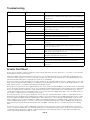
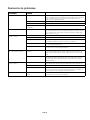
Troubleshooting
Arsenic Fact Sheet
Problem Cause Solution
Low/Slow Production Low Water Pressure Assure a minimum of 35 psi incoming water pressure. Watts sells a booster pump if
home water pressure is low. Make sure water supply is turned on and feed water valve
is all the way open.
Crimps in tubing Check tubing and straighten or replace as necessary.
Clogged Carbon Block Filter Replace Carbon Block Filter.
Fouled Reverse Osmosis Membrane Replace membrane.
Milky colored Water Air in system Air in the system is a normal occurrence with initial start up of the RO system. This milky
look will disappear during normal use within 1-2 weeks. If condition reoccurs after filter
change, drain tank 1 to 2 times.
Water constantly running, unit will not
shut off
Low water pressure See #1 Above
Crimp in supply tube Check tubing and straighten or repair as necessary
High water pressure Check incoming water pressure to make sure it does not exceed 100 psi. A pressure
regulator will be required (not included with the system).
High pressure in Tank Empty storage tank of water. Set tank air pressure between 5-7 psi. See previous page.
Low Pressure in Tank Use a Digital Air Gauge for best results. The empty tank pressure should be 5-7 psi.
See page 13.
Water from faucet vent hole or noise
from drain
Crimp or restriction in drain line Check tubing and straighten or repair as necessary. Straighten all drain lines. Clear
blockage. Cut off any excess tubing from the drain line and reinstall the drain line per
the instructions. Check for leaks
Drain tube clogged Caused from dishwasher or garbage disposal. Disconnect the 3⁄8" black line at the
drain, clean the 3⁄8" black line out with a wire, then reconnect. Check for leaks. blowing
air through the line will not always remove the clog.
Small amount of water in storage tank System starting up Normally it takes 3 hours to fill tank. Note: low incoming water pressure and/or
temperature can drastically reduce production rate.
Low water pressure See #1 above.
Too much air in tank Tank air pressure should be 5-7 psi when empty of water. If below 5 psi add air or bleed
if above 7 psi. Check only when tank is empty of water. See previous page.
Low water flow from faucet Check air pressure in tank Use a Digital Air Gauge for best results. The empty tank pressure should be 5-7 psi.
See page 13.
Arsenic (As) is a naturally occurring contaminant found in many ground waters. Arsenic in water has no color, taste or odor. It must be
measured by an arsenic test kit or lab test.
Public water utilities must have their water tested for arsenic. You can obtain the results from your water utility contained within your
consumer confidence report. If you have your own well, you will need to have the water evaluated. The local health department or the
state environmental health agency can provide a list of test kits or certified labs.
There are two forms of arsenic: pentavalent arsenic (also called As (V), As (+5)) and trivalent arsenic (also called As (III), As (+3)). In well
water, arsenic may be pentavalent, trivalent, or a combination of both. Although both forms of arsenic are potentially hazardous to your
health, trivalent arsenic is considered more harmful than pentavalent arsenic.
RO systems are very effective at removing pentavalent arsenic. A free chlorine residual will rapidly convert trivalent arsenic to pentavalent
arsenic. Other water treatment chemicals such as ozone and potassium permanganate will also change trivalent arsenic to pentavalent
arsenic. A combined chlorine residual (also called chloramine) where it does convert trivalent arsenic to pentavalent arsenic, may not
convert all the trivalent arsenic in to pentavalent arsenic. If you get your water from a public water utility, contact the utility to find out if
free chlorine or combined chlorine is used in the water system.
This Pure H2O reverse osmosis system is designed to remove up to 98% of pentavalent arsenic. It will not convert trivalent arsenic to
pentavalent arsenic. Under laboratory standard testing conditions, this system reduced 0.30 mg/L (ppm) pentavalent arsenic to under
0.010 mg/L (ppm) (the USEPA standard for drinking water). Actual performance of the system may vary depending on specific water
quality conditions at the consumer’s installation. In addition to the independent laboratory standard testing conditions Pure H2O has
conducted additional field testing on our reverse osmosis units to determine trivalent arsenic reduction capabilities. Based upon Pure
H2O field testing, it has been determined that the RO units are capable of reducing up to 67% of trivalent arsenic from the drinking
water.
This reverse osmosis system contains a replaceable component critical to the efficiency of the system. Replacement of the reverse
osmosis component should be with one of identical specifications, as defined by the manufacturer, to ensure the same efficiency and
contaminant reduction performance. Specific component identification and ordering information can be found in the maintenance
section of this manual, by phone at (888) 321-0500.

Page 16
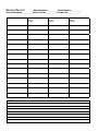
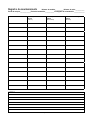
Service Record
Date of Purchase:__________ Date of Install:___________ Installed by:_____________
NOTES:
Model Number:__________ Serial Number:___________
Date Carbon Block Filter
H2O-F12
(6 months)
Reverse Osmosis Membrane
H2O-F16
(2-5 years)
Granular Activated Carbon Filter
H2O-F17
(12 months)

Page 17

IOM-WQ-H2O-DWRO300 2238 EDP# 88005433 © 2022 Watts
Limited Warranty
What Your Warranty Covers:
Watts warrants your H2O-DWRO300 (excluding replaceable filters) to be free from defects in material and workmanship under normal
usage for a period of one year from the date of original purchase. If any part of this system is found to be defective within the warranty
period, return the system after obtaining a return authorization from Watts (see below), and Watts will repair, or at Watts’ option, replace
the system at no charge.
How to Obtain Warranty Service:
To obtain warranty service, call 888-321-0500 for a return authorization number. Then, ship your system to our factory, freight and
insurance prepaid, with proof of the date of original purchase. Please include a note stating the warranty problem. Watts will repair, or
at Watts’ option, replace the system and ship it back to you at no charge.
What this Warranty Does Not Cover:
This warranty does not cover defects resulting from improper installation (installation contrary to Watts printed instructions), abuse,
misuse, misapplication, improper maintenance, neglect, alteration, accidents, casualties, fire, flood, freezing, environmental factors,
water pressure spikes, adverse water conditions or other events or conditions beyond Watts’ control.
This warranty will be void if defects occur due to failure to observe the following conditions:
1. The system must be hooked up to a potable municipal or well cold water supply.
2. The pH of the water must not be lower than 2 or higher than 11.
3. The incoming water pressure must be between 35 and 100 pounds per square inch.
4. Incoming water to the system cannot exceed 100 degrees F (38 degrees C.)
5. The hardness of the water should not exceed 10 grains per gallon, or 170 ppm.
6. Maximum incoming iron must be less than 0.2 ppm.
7. Incoming TDS/Total Dissolved Solids not to exceed 1800 ppm. This warranty does not cover any equipment that is relocated from
the site of its original installation.
This warranty does not cover any charges incurred due to professional installation.
Other Conditions:
If Watts chooses to replace the system, Watts may replace it with reconditioned equipment. Parts used in repairing or replacing the
system will be warranted for 90 days from the date the system is returned to you or for the remainder of the system’s original warranty
period, whichever is longer. This warranty is not assignable or transferable.
Limitations and Exclusions:
THE WARRANTY SET FORTH HEREIN IS GIVEN EXPRESSLY AND IS THE ONLY WARRANTY GIVEN BY WATTS WITH RESPECT TO
THE SYSTEM. WATTS MAKES NO OTHER WARRANTIES, EXPRESS OR IMPLIED. WATTS HEREBY SPECIFICALLY DISCLAIMS
ALL OTHER WARRANTIES, EXPRESS OR IMPLIED, INCLUDING THE IMPLIED WARRANTIES OF MERCHANTABILITY OR FITNESS
FOR A PARTICULAR PURPOSE. The warranty remedy described above shall constitute the sole and exclusive remedy for breach of
warranty, and Watts shall not be responsible for an incidental or consequential damages, including travel expense, telephone charges,
loss of revenue or profits, loss of time, inconvenience, loss of use of the equipment, or loss or damage caused by this system and its
failure to function properly. This warranty sets forth all of Watts responsibilities regarding this system.
Your Rights Under State Law:
Some states do not allow the exclusion or limitation of incidental or consequential damages and some states do not allow limitations
on how long implied warranties may last. Therefore, the above limitations or exclusions may not apply to you. This warranty gives
you specific legal rights and you may also have other rights, which vary from state to state. SO FAR AS IS CONSISTENT WITH
APPLICABLE STATE LAW, ANY IMPLIED WARRANTIES THAT MAY NOT BE DISCLAIMED, INCLUDING IMPLIED WARRANTIES OF
MERCHANTABILITY OR FITNESS FOR A PARTICULAR PURPOSE ARE LIMITED IN DURATION TO ONE YEAR FROM THE DATE OF
ORIGINAL PURCHASE.
USA: T: (888) 321-0500 • Watts.com
Canada: T: (905) 332-4090 • Watts.ca
Latin America: T: (52) 55-4122-0138 • Watts.com

Consulte la garantía adjunta para conocer los
parámetros de funcionamiento a fin de garantizar que
se utilice correctamente con el suministro de agua.
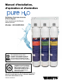
Manual de instalación,
funcionamiento
y mantenimiento
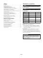
Sistemas de ósmosis inversa
de 3 etapas
Modelo: H2O-DWRO300
con reemplazo de filtro activado por botón
Sistema probado y certificado por la WQA
según las normas NSF/ANSI 42, 58 y NSF/
ANSI/CAN 372 para el cumplimiento de la
ausencia de plomo. Para ver las afirmaciones
específicas de rendimiento y reducción
verificadas y corroboradas mediante
datosde prueba, consulte la hoja de datos
derendimiento.
N.º de pieza: 88005233
ADVERTENCIA
!
Lea atentamente antes de realizar la instalación. Si
no sigue las instrucciones incluidas o no respeta
los parámetros de funcionamiento, es posible que
el producto no funcione bien.
Conserve este manual para consultarlo en el futuro.
PIENSE
PRIMERO EN
LA SEGURIDAD
P
R
O
B
A
D
O
Y
C
E
R
T
I
F
I
C
A
D
O
S
E
G
Ú
N
E
S
T
Á
N
D
A
R
E
S
I
N
D
U
S
T
R
I
A
L
E
S

Page 20
Resumen
Gracias por comprar este sistema de tratamiento de agua por
ósmosis inversa (OI) de Pure H2O de última generación. La
calidad del agua es una preocupación cada vez más presente
entre el público general. Es posible que haya oído hablar
sobre la presencia de contaminantes como arsénico, cromo
y Cryptosporidium o Giardia en el agua potable. También es
posible que existan otros problemas locales en el agua, como
altos niveles de plomo y cobre. El sistema de tratamiento de
Pure H2O está diseñado y probado para ofrecer agua potable
de alta calidad por muchos años. La siguiente es una breve
descripción general del sistema.
Sistema de ósmosis inversa:
La ósmosis es el proceso por el cual el agua atraviesa una
membrana semipermeable para equilibrar la concentración de
contaminantes a ambos lados de la membrana. Una membrana
semipermeable es una barrera que permite el paso de
determinadas sustancias, como el agua potable limpia, pero no
de otras, como arsénico y plomo.
La ósmosis inversa emplea una membrana semipermeable.
Sin embargo, mediante la aplicación de presión sobre toda
la membrana, concentra los contaminantes de un lado de la
membrana (como un colador) y el agua cristalina del otro. Por
este motivo, los sistemas de OI producen agua potable limpia y
agua residual que se expulsa del sistema. El sistema de ósmosis
inversa también emplea tecnología de filtro sólido de carbón y,
por lo tanto, puede ofrecer agua potable de calidad más alta
que los sistemas de filtrado con carbón por sí solos.
Usted ha comprado un sistema de ósmosis inversa de
3etapas basado en segmentos de tratamiento individuales
comprendidos en un sistema completo de filtrado de agua. Las
etapas son las siguientes:
ADVERTENCIA
!
No utilizar con agua microbiológicamente insegura o de
calidad desconocida sin una desinfección adecuada antes
odespués del sistema.
Si tiene dudas sobre la instalación del filtro de agua Watts,
comuníquese con un representante de Watts o consulte a un
plomero profesional
Descarte las piezas pequeñas que quedan después de la
instalación.
Si no se instala correctamente el sistema, se anula la garantía.
Manipule todos los componentes del sistema con cuidado. No deje
caer, no arrastre ni coloque boca abajo los componentes. Asegúrese
de que el piso debajo del sistema de filtración de agua esté limpio,
nivelado y tenga la solidez necesaria para soportar la unidad.
IMPORTANTE
PRECAUCIÓN
!
AVISO
Etapa 1 – Filtro de bloque de carbón. Se recomienda su
cambio cada 6meses.
La primera etapa contiene un filtro sólido de carbón de
5micrones. Este contribuye a garantizar que el cloro y
otras sustancias que causan mal sabor y olor se reduzcan
considerablemente. Es probado y verificado de manera
independiente para atrapar sustancias como polvo, cieno y
óxido.
Etapa 2 - Membrana de ósmosis inversa. Se recomienda
su cambio cada 2 a 5años.
La segunda etapa es el corazón del sistema de ósmosis
inversa, la membrana de OI de 50GPD (galones por día). Esta
membrana semipermeable remueve efectivamente los sólidos
disueltos totales y el sodio, así como una amplia gama de
contaminantes como cromo, arsénico, cobre, plomo y quistes
(por ejemplo, de Giardia y Cryptosporidium). El proceso de
obtención de esta agua potable de alta calidad lleva tiempo. Por
ese motivo, el sistema de tratamiento de agua por OI cuenta
con un tanque de almacenamiento.
Etapa 3: filtro de carbón activado granular, se recomienda
cambiarlo cada 12 meses.
La tercera etapa es un filtro de GAC (carbón activado
granular). Este filtro se utiliza después del tanque de
almacenamiento de agua, como filtro de pulido final del
agua del producto. Hay un promedio de 4 galones de agua
de rechazo por cada galón de agua producida. Por este
motivo, la vida útil del filtro GAC se extiende a 12 meses en
comparación con los 6 meses del bloque de carbón.
Nota: La vida útil de los filtros y de la membrana puede variar de
acuerdo con las condiciones del agua local y/o los patrones de
consumo.
Mantenimiento del sistema
Es importante cambiar los filtros según los intervalos
recomendados que se indican en este manual. Muchos
contaminantes no son detectables por el sabor. Además,
otros malos sabores y olores pueden hacerse evidente en el
transcurso del tiempo si no se reemplazan los filtros.
Es importante cambiar los filtros según los intervalos
recomendados que se indican en el manual del sistema. Al
cambiar los elementos filtrantes, preste especial atención a las
instrucciones de limpieza. Si tiene otras dudas, llame a nuestro
servicio de atención al cliente minorista al (888) 321-0500.
La page est en cours de chargement...
La page est en cours de chargement...
La page est en cours de chargement...
La page est en cours de chargement...
La page est en cours de chargement...
La page est en cours de chargement...
La page est en cours de chargement...
La page est en cours de chargement...
La page est en cours de chargement...
La page est en cours de chargement...
La page est en cours de chargement...
La page est en cours de chargement...
La page est en cours de chargement...
La page est en cours de chargement...
La page est en cours de chargement...
La page est en cours de chargement...
La page est en cours de chargement...
La page est en cours de chargement...
La page est en cours de chargement...
La page est en cours de chargement...
La page est en cours de chargement...
La page est en cours de chargement...
La page est en cours de chargement...
La page est en cours de chargement...
La page est en cours de chargement...
La page est en cours de chargement...
La page est en cours de chargement...
La page est en cours de chargement...
La page est en cours de chargement...
La page est en cours de chargement...
La page est en cours de chargement...
La page est en cours de chargement...
La page est en cours de chargement...
La page est en cours de chargement...
La page est en cours de chargement...
La page est en cours de chargement...
-
 1
1
-
 2
2
-
 3
3
-
 4
4
-
 5
5
-
 6
6
-
 7
7
-
 8
8
-
 9
9
-
 10
10
-
 11
11
-
 12
12
-
 13
13
-
 14
14
-
 15
15
-
 16
16
-
 17
17
-
 18
18
-
 19
19
-
 20
20
-
 21
21
-
 22
22
-
 23
23
-
 24
24
-
 25
25
-
 26
26
-
 27
27
-
 28
28
-
 29
29
-
 30
30
-
 31
31
-
 32
32
-
 33
33
-
 34
34
-
 35
35
-
 36
36
-
 37
37
-
 38
38
-
 39
39
-
 40
40
-
 41
41
-
 42
42
-
 43
43
-
 44
44
-
 45
45
-
 46
46
-
 47
47
-
 48
48
-
 49
49
-
 50
50
-
 51
51
-
 52
52
-
 53
53
-
 54
54
-
 55
55
-
 56
56


Watts Pure H20-DWRO300 Guide d'installation
- Taper
- Guide d'installation
dans d''autres langues
Documents connexes
Autres documents
-
vitapur VRO-3U Manuel utilisateur
-
 Outsunny A20-075 Assembly Instructions
-
brondell RF-50 Le manuel du propriétaire
-
OmniFilter RO2000 Series Manuel utilisateur
-
GE Water Dispenser PXRQ15F Manuel utilisateur
-
-
-
-
-
