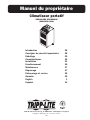
Tripp Lite Portable Air Conditioning Unit Le manuel du propriétaire
- Catégorie
- Climatiseurs split-system
- Taper
- Le manuel du propriétaire

PROTECT YOUR INVESTMENT!
Register your product for quicker service and ultimate peace of mind.
You could also win an ISOBAR6ULTRA surge protector—a $50 value!
www.tripplite.com/warranty
1
Portable Air Conditioning Unit
SRCOOL18K, SRCOOL24K
(208/240V, 60 Hz)
Owner’s Manual
Introduction 2
Important Safety Instructions 2
Unpacking 3
Features 4
Installation 5
Operation 10
Maintenance 11
Troubleshooting 11
Storage and Service 13
Warranty and Product Registration 13
Español 14
Français 27
1111 W. 35th Street, Chicago, IL 60609 USA • www.tripplite.com/support
Copyright © 2015 Tripp Lite. All rights reserved.

SYST
RPS
SYST
RPS
STAT
DUPLX
SPEED
MODE
1
5
X
MASTR
STACK
SYST
RPS
STAT
DUPLX
SPE
ED
MODE
1
5
X
3
1
X
3
3
X
MASTR
STACK
SY
ST
RPS
STAT
DUPLX
S
PEED
MODE
1
5
X
3
1
X
3
3
X
MASTR
STACK
4
7
X
5
0
SYST
RPS
SYST
RPS
STAT
DUPLX
SPEED
MODE
1
5
X
MASTR
STACK
SYST
RPS
STAT
DUPLX
SPEED
MODE
1
5
X
3
1
X
3
3
X
MASTR
STACK
SYST
RPS
STAT
DUPLX
SPEED
MODE
1
5
X
3
1
X
3
3
X
MASTR
STACK
4
7
X
5
0
SYST
RPS
SYST
RPS
STAT
DUPLX
SPEED
MODE
1
5
X
MASTR
STACK
SYST
RPS
STAT
DUPLX
SPEED
MODE
1
5
X
3
1
X
3
3
X
MASTR
STACK
SYST
RPS
STAT
DUPLX
SPEED
MODE
1
5
X
3
1
X
3
3
X
MASTR
STACK
4
7
X
5
0
SRCOOL18K SRCOOL24K SRCOOL18K SRCOOL24K
2
Introduction
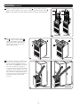
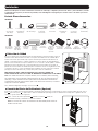
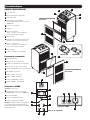
The self-contained Portable Air Conditioning Unit provides 18,000 or 24,000 BTUs of supplemental cooling capacity. Designed for IT
environments, it’s ideal for cooling overheated rack enclosures, IT equipment hot spots and network closets without access to facility air
conditioning. The Portable Air Conditioning Unit can focus cool air through its flexible cooling duct or cool a small room through its louvered vent.
The SRCOOL24K’s cooling output feature allows cool air to be split between two racks. It also filters and dehumidifies air to improve operating
conditions and equipment reliability. Condensate is re-evaporated for drip-free operation, so you won’t waste time emptying water collection
tanks. The self-contained design does not require any plumbing or special circuits, so setup is quick and easy. Eco-friendly R410A refrigerant
meets environmental standards worldwide.
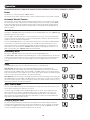
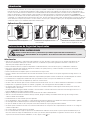
Recommended Applications:
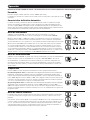
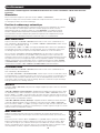
Important Safety Instructions
SAVE THESE INSTRUCTIONS
This manual contains instructions and warnings that should be followed during the installation, operation
and storage of this product. Failure to heed these warnings may affect your warranty.
Warnings
• The individual user should determine prior to use whether this device is suitable, adequate or safe for the use intended. Since individual
applications are subject to great variation, the manufacturer makes no representation or warranty as to the suitability or fitness of this device
for any specific application.
• Install the unit indoors, away from extreme temperatures or humidity, direct sunlight, dust and conductive contaminants.
• Leave adequate space around the unit for ventilation, with rear and vented sides not less than 20 inches (51 cm) from walls or other
obstacles.
• Install the unit on a flat surface with a gradient no more than 10°.
• Connect the unit directly to a grounded AC power outlet. Failure to do so may cause an electric shock or fire.
• This unit is designed to supply supplemental cooling for localized hot spots. It is not intended for continuous use.
• The power supply for the unit must be rated in accordance with the unit’s nameplate.
• Do not modify the plug nor use an adapter that would eliminate the ground connection.
• Do not use an extension cord to connect the unit to an AC outlet. Use only the power cord that came with the unit.
• Comply with all applicable wiring and safety regulations, such as National Electrical Code (NEC) in the United States.
• Do not plug additional equipment into the outlet where the unit is plugged in. Overloading the outlet may cause an electric shock or fire.
• Do not attempt to turn the unit on or off by connecting or disconnecting the AC plug. A serious electric shock may occur. Use the ON/OFF
button to turn the unit on or off.
• Turn the unit off and unplug it from the AC outlet before performing maintenance.
• Before connecting the unit to a dedicated drainage system, turn it off and unplug it. There is a risk of electric shock while the unit is plugged in.
• Maintenance should be performed by trained personnel only.
• Do not use thinners, alcohol, detergents or abrasive brushes to clean the unit’s cabinet. These items may damage the cabinet.
• Do not pour water over the unit. This may cause an electric shock and damage the unit.
• Do not operate the unit without the air filter. This may cause dust accumulation that may damage the unit.
• Do not attempt to operate the unit in a room with inadequate air circulation. Provide makeup air in accordance with applicable building codes.
• Do not place objects on top of the unit.
• Use of this equipment in life support applications where failure of this equipment can reasonably be expected to cause the failure of the life
support equipment or to significantly affect its safety or effectiveness is not recommended. Do not use this equipment in the presence of a
flammable anesthetic mixture with air, oxygen or nitrous oxide.
1. Cooling a small room. 2. Cooling an overheated rack enclosure. 3. Cooling an equipment hot spot inside or
outside a rack enclosure.

1
2
3
A
B
C
3
1
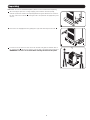
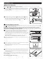
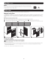
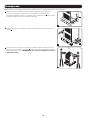
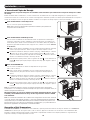
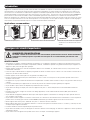
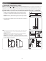
After removing the protective covering, wrapping, foam insulation and other packing
materials (instructions found in the Unpacking Instructions guide attached to the outside of
the unit), remove the four bolts
A
securing the unit to the pallet with an appropriately sized
wrench.
2
Remove the two shipping brackets by pulling the top lip under and away from the unit
B
.
3
Position at least one person on each side of the unit and slowly push it toward the back of
the shipping pallet
C
until all four casters go over the edge of the pallet and touch the floor.
WARNING: Use at least one assistant when removing the unit from the pallet.
Unpacking
Note: Make sure the unit and attached pallet is placed on a level surface before unpacking.

VU
TS
O
W
Q
M
Y
N
X
R
P
Z
I
SRCOOK18K SRCOOK24K
E
D
F
L
H
K
G
J
C
B
A
4
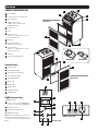
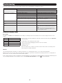
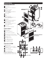
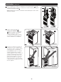
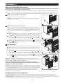
Features
SRCOOL18K/SRCOOL24K
A
Cool Air Output
B
Louvered Vent Insert (Pre-Installed)
C
Warm Air Exhaust
D
SNMP Accessory Slot*
* SNMP card pre-installed with
SRCOOL24K model
E
Control Panel
F
Casters
G
Condenser Filters
(Included – see Maintenance section
for filter replacement)
H
Front Panel
I
Cooling Duct Adapter
(Optional, Varies by Model)
J
Evaporator Filters
(Included – see Maintenance section
for filter replacement)
K
Rear Panel
L
Evaporator Drainage Outlets
Control Panel
M
Numeric Display
N
Operating Mode LEDs
O
Temperature Control Buttons
P
Fan Speed Mode LEDs
Q
“FAN SPEED” Button
R
“QUIET” LED
S
“QUIET” Button
T
“TIMER” Button
U
“FUNCTION” Button
V
“POWER” Button
SNMP Connections
(SRCOOL24K Only)
W
PS/2 Port (for use with ENVIROSENSE
accessory – included with SRCOOL24K)
X
Mini-DIN Serial Port
Y
RJ45 Ethernet Network Port
Z
SNMP Reset Button
Note: Use a pin, paper clip, or point tool to
access the recessed reset button. Do not
use excessive force when engaging the reset
button.
SRCOOL18K/SRCOOL24K
Front View
SRCOOL18K/SRCOOL24K
Rear View
Control Panel
SNMP Connections

>
20 in. (51 cm)
>
20 in. (51 cm)
WALL
WALL
100 in.
2
(645 cm
2
)
Vent (For
Confined Spaces)
1
2-1
A
B
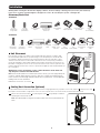
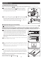
5
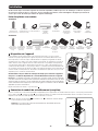
Installation
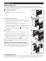
Warning: After removing the unit from the shipping container, check for damage or missing parts (refer to the parts list below).
If you notice a problem, visit www.tripplite.com/support for service. Do not attempt to operate a damaged unit.
Accessory Parts List:
SRCOOL18K
2 x Gray
Exhaust Duct
(Longer Tube)
1 x Black
Cooling Duct
(Shorter Tube)
2 x Exhaust Duct
Adapter
2 x Adjustable
Exhaust Panel
(2 Sections)
4 x Self-Tapping
Screw
Cooling Duct
Adapter (Optional)
Louvered Vent Insert
(Pre-installed)
Drainage
Plug
(2 Pre-installed)
2 x Gray
Exhaust Duct
(Longer Tube)
2 x Black
Cooling Duct
(Shorter Tube)
2 x Exhaust Duct
Adapter
2 x Adjustable
Exhaust Panel
(2 Sections)
4 x Self-Tapping
Screw
Cooling Duct
Adapter – 2 pcs.
(Optional)
Louvered Vent
Insert
(Pre-installed)
Drainage
Plug
(2 Pre-installed)
ENVIROSENSE
Environmental
Sensor
SNMP
Configuration
Cable
SRCOOL24K
1
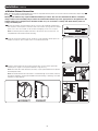
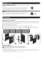
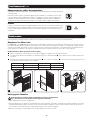
Unit Placement
Place the unit on a flat, level surface near a grounded AC outlet rated in accordance with
the unit nameplate (90-110% of specified voltage). Leave adequate space around the unit
for ventilation, with the front and rear not less than 20 inches (51 cm) from walls or other
obstacles. Place the unit in a location with convenient access to a drop ceiling or window to
provide the straightest, shortest path available for the flexible exhaust duct. If you plan to use
the flexible cooling duct to focus cool air on a specific rack enclosure or device, place the unit
near the targeted rack enclosure or device to provide the straightest, shortest path available for
the cooling duct.
Warning: Do not use an extension cord to connect the unit to an AC outlet. Use
only the power cord that came with the unit.
Note: If the unit will operate in a confined space (such as closet), you must supply makeup air
in order to maintain airflow efficiency. A 100 in.
2
(645 cm
2
) or larger vent installed near the
bottom of the door should supply adequate makeup air for a typical closet. Consult applicable
building codes for more information.
Exhaust hose not shown—see Section
3
.
2
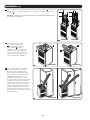
Cooling Duct Connection (Optional)
The pre-installed louvered vent insert is appropriate for room cooling applications. If you plan to cool a room, skip step
2
and proceed to step
3
.
If you plan to use the flexible cooling duct to focus cool air on a specific device or rack enclosure, follow the instructions below.
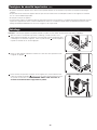
2-1
Remove the louvered vent insert
A
by removing the screws
B
using a Phillips screwdriver
and lifting the vent from the unit.
Note: The SRCOOL24K’s cooling duct connection allows cool air to be split between two
racks.

2-2
A A
B B
SRCOOL18K SRCOOL24K
1
2
1
2
2-3
AA
BB
2-4
SRCOOL18K SRCOOL24K
SRCOOL18K SRCOOL24K
6
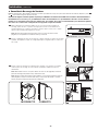
Installation (continued)
2-2
Align the cooling duct adapter with the cool air output
A
. Using a Phillips screwdriver,
secure it to the unit with the screws used for securing the pre-installed louvered vent
B
.
Note: The SRCOOL24K cooling duct adapter requires four additional screws (included).
2-3
Connect the flexible black cooling duct
tube
A
to the cooling duct adapter
B
.
Align the duct with the circular adapter
opening, push the duct downward and
turn the duct clockwise until it screws
into the adapter solidly.
2-4
Place the other end of the cooling duct near
the air intake of the target device or rack
enclosure, using the straightest, shortest
path available (for SRCOOL24K, repeat with
the second cooling duct). If you plan to
cool a rack enclosure, place the end of the
cooling duct over a perforated area near the
top of the enclosure’s front door (or near the
top of the bank of equipment that requires
cooling). Cool air will sink and spread across
the air intakes at the front of the rack
enclosure.

1
2
1
2
3-1
3-2
B
A
1
2
1
2
A
B
Self-Tapping Screw
Vertical
Window
Opening
Horizontal Window
Opening
4-1
4-2
4-3
4-4
Ceiling Panel
(From Below)
Ceiling Panel
(From Above)
Exhaust Panel
7
Installation (continued)
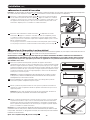
3
Exhaust Duct Connection
Note: The SRCOOL18K and SRCOOL24K both contain two exhaust ducts (one for each warm air exhaust) and two exhaust duct adapters.
Repeat steps
3-1
and
3-2
install the second exhaust duct and adapter.
3-2
Connect the other end of the exhaust duct
A
to the exhaust duct adapter
B
. Align the
duct with the circular adapter opening, push the duct inward and turn the duct clockwise
until it screws into the adapter solidly. Repeat for the second exhaust duct tube.
If you plan to connect the exhaust duct to a drop ceiling, proceed to step
4
. If you plan to
connect the exhaust duct to a window, proceed to step
5
.
4
Drop Ceiling Exhaust Connection
Note: The SRCOOL18K and SRCOOL24K both contain two adjustable exhaust panels (one for each warm air exhaust duct). Repeat steps
4-1
through
4-4
to install the second exhaust panel.
Warning: Some ceilings may require modified installation procedures. The user must determine the fitness of hardware
and procedures before installing. The procedures described in this manual may not be appropriate for all applications. The
exhaust panels are not designed to be installed side-by-side.
4-3
Slide the ceiling panel out of the way and place the exhaust panel inside the ceiling space.
Allow the exhaust panel to rest on top of the ceiling grid.
Note: There must be at least 10 inches (25.4 cm) of open space above the exhaust panel
to allow adequate airflow.
4-4
Slide the ceiling panel back into place so that it adjoins the exhaust panel and closes any
gaps in the ceiling. A tight seal will permit maximum cooling efficiency. If the installation
is permanent, trim the ceiling panel so it doesn’t overlap the ceiling grid. Repeat for the
second exhaust duct tube.
Note: The flexible exhaust duct can extend to a maximum length of 118 inches (300 cm).
Provide the straightest, shortest path available. Excessive bending or stretching of the duct will
reduce cooling efficiency.
After completing step
4
, proceed to step
6
.
4-1
Choose a removable drop ceiling panel near the unit to provide the straightest, shortest
path available for the flexible exhaust duct. Measure the width of the ceiling panel,
including the portion that rests on the ceiling grid. Combine the two sections of the
adjustable exhaust panel, then adjust the exhaust panel to match the width of the ceiling
panel. After the exhaust panel is set to the correct width, use the included self-tapping
screw to lock it in place.
Note: The exhaust panel can adjust from 20.5 to 49.2 inches (52.1 to 104.1 cm).
Certain installations may require trimming the exhaust panel for a proper fit.
4-2
Insert the exhaust duct adapter into the oblong hole in the adjustable exhaust panel. The
adapter will snap into place.
3-1
Connect the flexible gray exhaust duct tube
A
to the warm air exhaust vent on the rear
panel of the unit
B
. Align the duct with the circular vent opening, push the duct inward
and turn the duct clockwise until it screws into the exhaust vent solidly. Repeat for the
second exhaust duct tube.

Self-Tapping Screw
Vertical
Window
Opening
Horizontal Window
Opening
5-1
5-2
Self-Tapping Screw
Vertical
Window
Opening
Horizontal Window
Opening
Self-Tapping Screw
Vertical
Window
Opening
Horizontal Window
Opening
INCORRECT CORRECT
5-3
8
Installation (continued)
5
Window Exhaust Connection
Note: The SRCOOL18K and SRCOOL24K both contain two adjustable exhaust panels (one for each warm air exhaust duct). Repeat steps
5-1
through
5-3
to install the second exhaust panel.
Warning: Some windows may require modified installation procedures. The user must determine the fitness of hardware
and procedures before installing. The procedures described in this manual may not be appropriate for all applications. The
exhaust panels are not designed to be installed stacked on top of one another or side-by-side. Each exhaust panel can
occupy one window pane.
5-1
Measure the window opening. Combine the two sections of the adjustable exhaust panel,
then adjust the exhaust panel to match the width of the window opening. After the exhaust
panel is set to the correct width, use the included self-tapping screw to lock it in place.
Note: The exhaust panel can adjust from 20.5 to 49.2 inches (52.1 to 104.1 cm). It is
compatible with vertical and horizontal mounting.
5-2
Insert the exhaust duct adapter into the oblong hole in the adjustable exhaust panel. The
adapter will snap into place. Repeat for the second exhaust duct tube.
5-3
Insert the exhaust panels into the window opening, then close the window against the
exhaust panels. A tight seal will permit maximum cooling efficiency.
Note: There must be at least 20 inches (50.8 cm) of open space behind the rear panel to
allow adequate airflow.
Note: The flexible exhaust duct can extend to a maximum length of 118 inches (300 cm).
Provide the straightest, shortest path available. Excessive bending or stretching of the duct
will reduce cooling efficiency.

1
1
2
2
1
1
2
2
1
1
2
2
6-1
1
2
3
TO EXTERNAL
DRAIN
A
B
D
E
C
9
Installation (continued)
6
Drainage Plug Insertion
Warning: The unit’s built-in re-evaporator will not function until you insert the drainage plug into the drainage outlet.
When the unit cools or dehumidifies, condensation forms. The unit has a built-in re-evaporator that allows it to expel condensation through the
warm air exhaust stream. This feature allows the unit to operate indefinitely without requiring you to empty a water collection tank. The unit ships
with both the upper and lower drainage plugs pre-installed.
6-1
Cooling Mode with Re-Evaporation
This is the default mode of operation.
Note: Both drainage plugs must remain installed to enable re-evaporation of
condensation.
6-2
Cooling Mode without Re-Evaporation
Use this mode in high humidity environments when the unit’s capacity to evaporate
condensation exceeds the amount of condensation produced. Also use this mode during
shut downs when the “Water (Tank) Full” error frequently occurs (see Troubleshooting
section for more information on error codes).
1
Remove the rear panel by lifting it up by its sides to disengage from the unit, then
pulling away to detach. Remove the top and bottom drainage plugs.
2
Route two user-supplied 3/4 inch or 18 mm drain lines
A
through the rear panel’s
top and bottom holes
B
, and attach to each of the unit’s evaporator drainage outlets
C
, and route the open ends of the drain lines to external drainage.
3
To reattach the rear panel, align the panel hooks
D
with the unit’s slots
E
, push in to
engage, then push down to secure the panel to the unit.
6-3
Dehumidify Mode
Use this mode in environments where the air temperature is already cold
(68° F / 20° C or less).
1
Remove the rear panel by lifting it up by its sides to disengage from the unit, then
pulling away to detach. Remove the top and bottom drainage plugs.
2
Route two user-supplied 3/4 inch or 18 mm drain lines
A
through the rear panel’s
top and bottom holes
B
, and attach to each of the unit’s evaporator drainage outlets
C
, and route the open ends of the drain lines to external drainage.
3
To reattach the rear panel, align the panel hooks
D
with the unit’s slots
E
, push in to
engage, then push down to secure the panel to the unit.
Note: If the drainage system becomes clogged, a small internal reservoir will collect
condensation. If the drainage system is not cleared before the internal reservoir fills, the unit
will shut down automatically.
Warning: Before connecting the unit to a dedicated drainage system, turn it off
and unplug it. There is a risk of electric shock while the unit is plugged in.
Note: If your building’s cooling system has night or weekend thermostat setbacks, has periodic
shutdowns, or has limited cooling capacity, you may need to consider alternatives to the
standard installation. This product is meant to be used as a supplemental cooling device, and
cannot make up for significant fluctuations in building temperature or humidity.
Low Temperature Operation
The SRCOOL18K/SRCOOL24K is a high performance cooler capable of producing very cold air output. When using the SRCOOL18K/SRCOOL24K
in environments that are already cold (68° F / 20° C or less), Tripp Lite recommends using the Dehumidify Mode only. This will allow the unit to
continue to provide supplemental cooling while preventing any evaporator icing issues caused by the low room temperature.

10
Operation
Warning: Install the unit according to the instructions in the “Installation” section before attempting to operate it.
Power
Turn the unit on or off by pressing the “POWER” button.
The unit has a three-minute compressor delay in order to prevent potential circuit overloads at start up.
Automatic Restart Feature
The unit will turn on and resume operation automatically when power is restored after a power outage.
The unit will use the same settings that it used immediately before the power outage occurred. Note:
If the power outage is brief, the unit will run the fan alone for three minutes before resuming normal
operation. The delay allows the compressor to depressurize so the unit will function properly when it
enters Cool mode.
Cool Mode
Pressing the “FUNCTION” button cycles between Cool mode and Dehumidify mode. The “COOLING” LED
illuminates when Cool mode is active.
Press the TEMP+ and TEMP- buttons to set the temperature in Cool mode. The selected temperature
is shown on the numeric display. Once set, the desired temperature will blink five times after which the
display will show the current room temperature.
Press the “FAN SPEED” button to cycle between high, medium and low fan speeds. An LED illuminates
to indicate the selected fan speed. When speed is set on AUTO, the unit will automatically select a
fan speed based on the set and ambient temperatures. If ambient temperature is lower than the set
temperature, the fan will run and the “COOLING” LED will blink to indicate that the compressor is off.
When cooling resumes, the “COOLING” LED will remain illuminated.
Dehumidify Mode
Pressing the “FUNCTION” button cycles between Cool mode and Dehumidify mode.
The “DEHUMIDIFY” LED illuminates when Dehumidify mode is active. In Dehumidify mode, the fan runs
at a fixed speed and temperature controls are irrelevant. For optimal performance in Dehumidify mode,
close windows and doors, remove the top drain plug and route user-supplied drain line to external
drainage.
Timer
The “TIMER” button allows you to schedule the unit to turn on or off automatically.
Timer On (Note: The unit must be off to activate the Timer On function. Confirm that mode,
temperature and fan speed settings are correct before activating the Timer On function.) Activate the
timer by pressing the “TIMER” button. Press the TEMP+ and TEMP- buttons to set the delay (in hours)
before the unit will turn on. The number of hours is shown on the numeric display. The number will flash
on the screen five times before returning to the current temperature.
Timer Off (Note: The unit must be on to activate the Timer Off function.) Activate the timer by pressing
the “TIMER” button. Press the TEMP+ and TEMP- buttons to set the delay (in hours) before the unit will
turn off. The number of hours is shown on the numeric display. The number will flash on the screen five
times before returning to the current temperature.
Quiet Control Mode
The unit includes a Quiet Control mode which regulates the cooling via the timer and microprocessor to
achieve quieter operation levels when noise is an issue.
To activate, press the “QUIET” button. The Quiet LED will turn on. Set the desired temperature and
then set the timer to the duration of the Quiet Control mode cycle. During the course of the cycle,
the microprocessor memory will adjust the preset temperature by 0.9°F (0.5°C) every 30 minutes
until it reaches the desired temperature. Once the temperature is reached, the unit will maintain the
temperature for the duration of the set time.
Changing Degree Units
The unit can display temperature in both Celsius and Fahrenheit. The default setting is Fahrenheit.
To toggle between temperature modes, put the unit in standby mode. The air conditioner is in standby
mode when it is plugged into live AC power, but powered off. Then, hold the “FUNCTION” key for 10
seconds. To verify the degree units have changed, power on the unit.

1 2 3
A
B
C
11
Operation (continued)
Maintenance
Periodic maintenance extends the unit’s lifespan and permits maximum operating efficiency.
Replacing the Air Filters
The SRCOOL18K and SRCOOL24K use replaceable air filters available for purchase at your local hardware or home improvement store (two per
front and rear panel, see below for filter dimensions). It is important to keep the air filters clean and free of dust. When the filters are dirty or
clogged with dust, it decreases cooling efficiency and can threaten air quality. Tripp Lite recommends cleaning the filters at least once every two
weeks.
Filter Replacement (Front and Rear Panels)
1
Remove the panel by lifting it up by its sides to disengage from the unit, then pulling away to detach.
2
On the inside of the front panel, replace both of the used filters with two new filters
A
(see table below for filter dimensions).
3
To reattach the panel, align the panel hooks
B
with the unit’s slots
C
, push in to engage, then push down to secure the panel to the unit.
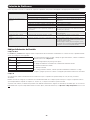
Filter Type Panel Location Number of Filters Filter Dimensions
Condenser Filter Front 2 12 x 18 x 1”
Evaporator Filter Rear 2 14 x 18 x 1”
Alarm
When the water tank is full, the unit will display the message “E4” on its screen. To resume normal
function, turn the unit off, remove the drainage plug and drain the excess water from the unit. Replace
the plug and turn the unit on to begin cooling.
Cleaning the Cabinet
Before cleaning the cabinet, turn the unit off and unplug it!
There is a risk of electric shock while the unit is plugged in.
1. Turn the unit off and unplug it.
2. Wipe the unit with a dry, non-abrasive cloth. Do not use gasoline, benzene, thinners or other harsh chemicals that may damage the surface.
Do not pour water directly over the unit or into the working parts. This causes a risk of electrical shock and deterioration of electrical
components and wiring insulation.
3. In extreme cases, wipe the unit with a damp cloth to remove residue.

12
Troubleshooting
Review the possible solutions below. If the problem persists, please visit www.tripplite.com/support for service.
Problem Possible Cause Possible Solution
The unit does not function. The unit is turned off. Turn the unit on. (See “Operation” section.)
The unit is not plugged in. Plug the unit into a suitable outlet.
Main power is off. Check fuses or circuit breaker.
Cooling performance is unsatisfactory. The air exhaust or intake is blocked. Confirm that all ducts and intakes are clear of obstructions.
The temperature setting is too high. Adjust the temperature setting.
The fan speed setting is too low. Adjust the fan setting.
The air filters are dirty. Clean or replace the air filters.
The wattage of the rack enclosure, the size of the room or the
ambient temperature exceeds the cooling capacity of a single
unit.
Install additional units or contact Tripp Lite for additional cooling
solutions suitable for your application.
The unit leaks water. The drainage plug is not installed. Insert the drainage plug in the drainage outlet. (See “Installation”
section.)
The unit generates excessive noise or
vibration.
The unit is on an uneven or unstable surface. Move the unit to a level, stable surface.
The unit has ice or frost buildup. The unit is operating in an environment with excess humidity. OPTION 1: Turn off the unit, and let the unit defrost. Once
defrosted, ensure the unit is operating with the fan speed set
on HIGH.
OPTION 2: Turn off the unit, and let the unit defrost. Once
defrosted, operate the unit in DEHUMIDIFY MODE, or increase
the desired temperature setpoint.
Additional Display Codes
Error Codes
The Tripp Lite SRCOOL18K and SRCOOL24K has the ability to continually monitor itself. Should an error occur, the display will show one of 5
codes:
Code E4 can be cleared by emptying the water tank. Consult the Alarm entry in the Operation
section for details.
For Codes E0, E1, E2, and E3 follow these steps:
1. Power cycle the unit by unplugging it from the source for 5 minutes.
2. Plug the unit back in.
3. Restart the unit.
If the code remains clear, continue to operate the unit as normal. If the code returns, please
contact Tripp Lite for further instructions.
Error Code Description
E0 Internal Communication Error
E1 Indoor Temperature Sensor Error
E2 Internal Temperature Sensor Error
E3 Refrigerant Error
E4 Water Full
dF Code
“dF” will display when the unit detects a condition in which the coil is operating below 33.8° F (1° C) for more than 15 minutes.
During a dF code event, the unit’s fans will run without the compressor to prevent the evaporator from freezing up. Once the coil temperature is
above 33.8° F (1° C), the compressor will resume normal operation.
If this condition persists, the unit is operating in an environment that is too cold. Tripp Lite recommends that the unit operate in Dehumidify mode
only if operating temperatures are below 68° F (20° C). See Low Temperature Operation in section
6-3
for more information.

13
Warranty
1-YEAR LIMITED WARRANTY
Seller warrants this product, if used in accordance with all applicable instructions, to be free from original defects in material and workmanship for a period of 1 year from the date of initial purchase. If the
product should prove defective in material or workmanship within that period, Seller will repair or replace the product, in its sole discretion. Service under this Warranty can only be obtained by your delivering
or shipping the product (with all shipping or delivery charges prepaid) to: Tripp Lite, 1111 W. 35th Street, Chicago, IL 60609 USA. Seller will pay return shipping charges.
THIS WARRANTY DOES NOT APPLY TO NORMAL WEAR OR TO DAMAGE RESULTING FROM ACCIDENT, MISUSE, ABUSE OR NEGLECT. SELLER MAKES NO EXPRESS WARRANTIES OTHER THAN THE WARRANTY
EXPRESSLY SET FORTH HEREIN. EXCEPT TO THE EXTENT PROHIBITED BY APPLICABLE LAW, ALL IMPLIED WARRANTIES, INCLUDING ALL WARRANTIES OF MERCHANTABILITY OR FITNESS, ARE LIMITED IN
DURATION TO THE WARRANTY PERIOD SET FORTH ABOVE; AND THIS WARRANTY EXPRESSLY EXCLUDES ALL INCIDENTAL AND CONSEQUENTIAL DAMAGES. (Some states do not allow limitations on how
long an implied warranty lasts, and some states do not allow the exclusion or limitation of incidental or consequential damages, so the above limitations or exclusions may not apply to you. This Warranty
gives you specific legal rights, and you may have other rights which vary from jurisdiction to jurisdiction).
WARNING: The individual user should determine prior to use whether this device is suitable, adequate or safe for the use intended. Since individual applications are subject to great variation, the
manufacturer makes no representation or warranty as to the suitability or fitness of this device for any specific application.
PRODUCT REGISTRATION
Visit www.tripplite.com/warranty today to register your new Tripp Lite product. You’ll be automatically entered into a drawing for a chance to win a FREE Tripp Lite product!*
* No purchase necessary. Void where prohibited. Some restrictions apply. Open to U.S. residents only. See www.tripplite.com for details.
Regulatory Compliance Identification Numbers
For the purpose of regulatory compliance certifications and identification, your Tripp Lite product has been assigned a unique series number. The series number can be found on the product nameplate label,
along with all required approval markings and information. When requesting compliance information for this product, always refer to the series number. The series number should not be confused with the
marking name or model number of the product.
WEEE Compliance Information for Tripp Lite Customers and Recyclers (European Union)
Under the Waste Electrical and Electronic Equipment (WEEE) Directive and implementing regulations, when customers buy new electrical and electronic equipment from Tripp Lite they are
entitled to:
• Send old equipment for recycling on a one-for-one, like-for-like basis (this varies depending on the country)
• Send the new equipment back for recycling when this ultimately becomes waste
Tripp Lite has a policy of continuous improvement. Product specifications are subject to change without notice.
Storage and Service
Warranty and Product Registration
Storage
Before storing the unit, confirm that the ducts and vents are secured or removed and cared for properly. Also confirm that the unit is drained of
condensation.
Service
Your Tripp Lite product is covered by the warranty described in this manual. A variety of Extended Warranty and On-Site Service Programs are also
available from Tripp Lite. For more information on service, visit www.tripplite.com/support. Before returning your product for service, follow these
steps:
1. Review the installation and operation procedures in this manual to insure that the service problem does not originate from a misreading of the
instructions.
2. If the problem continues, do not contact or return the product to the dealer. Instead, visit www.tripplite.com/support.
3. If the problem requires service, visit www.tripplite.com/support and click the Product Returns link. From here you can request a Returned
Material Authorization (RMA) number, which is required for service. This simple on-line form will ask for your unit’s model and serial numbers,
along with other general purchaser information. The RMA number, along with shipping instructions will be emailed to you. Any damages (direct,
indirect, special or consequential) to the product incurred during shipment to Tripp Lite or an authorized Tripp Lite service center is not covered
under warranty. Products shipped to Tripp Lite or an authorized Tripp Lite service center must have transportation charges prepaid. Mark the
RMA number on the outside of the package. If the product is within its warranty period, enclose a copy of your sales receipt. Return the
product for service using an insured carrier to the address given to you when you request the RMA.
1111 W. 35th Street, Chicago, IL 60609 USA • www.tripplite.com/support

14
Unidad Portátil de Aire Acondicionado
SRCOOL18K, SRCOOL24K
(208/240V, 60 Hz)
Manual del Propietario
Introducción 15
Instrucciones de Seguridad Importantes 15
Desempacado 16
Características 17
Instalación 18
Operación 23
Mantenimiento 24
Solución de Problemas 24
Almacenamiento y Servicio 26
Garantía 26
English 1
Français 27
1111 W. 35th Street, Chicago, IL 60609 USA • www.tripplite.com/support
Copyright © 2015 Tripp Lite. Todos los derechos reservados.

SY
ST
RPS
SYST
RPS
STAT
D
UPLX
SPEED
MODE
1
5
X
MASTR
STACK
SYST
RPS
STAT
DUPLX
SPE
ED
MODE
1
5
X
3
1
X
3
3
X
MASTR
STACK
SYST
RPS
STAT
DUPLX
S
PEED
MO
DE
1
5
X
3
1
X
3
3
X
MASTR
STACK
4
7
X
5
0
SYST
RPS
SYST
RPS
STAT
DUPLX
SPEED
MODE
1
5
X
MASTR
STACK
SYST
RPS
STAT
DUPLX
SPEED
MODE
1
5
X
3
1
X
3
3
X
MASTR
STACK
SYST
RPS
STAT
DUPLX
SPEED
MODE
1
5
X
3
1
X
3
3
X
MASTR
STACK
4
7
X
5
0
SYST
RPS
SYST
RPS
STAT
DUPLX
SPEED
MODE
1
5
X
MASTR
STACK
SYST
RPS
STAT
DUPLX
SPEED
MODE
1
5
X
3
1
X
3
3
X
MASTR
STACK
SYST
RPS
STAT
DUPLX
SPEED
MODE
1
5
X
3
1
X
3
3
X
MASTR
STACK
4
7
X
5
0
SRCOOL18K SRCOOL24K SRCOOL18K SRCOOL24K
15
Introducción
La unidad autónoma portátil de aire acondicionado proporciona 18,000 o 24,000 BTU de capacidad suplementaria de enfriamiento. Diseñada
para entornos de TI, es ideal para enfriar gabinetes, puntos calientes de equipo de TI y gabinetes de cableado de redes sobrecalentados sin
acceder al aire acondicionado de las instalaciones. La Unidad Portátil de Aire Acondicionado puede concentrar el aire frío mediante su conducto
flexible de enfriamiento o enfriar un pequeño cuarto mediante su ventila apersianada. La característica de enfriamiento del SRCOOL24K
permite al aire frío dividirse entre dos racks. Además filtra y seca el aire para mejorar las condiciones de operación y confiabilidad del equipo. El
condensado es re-evaporado para una operación libre de goteos, de modo que usted no gaste tiempo vaciando tanques recolectores de agua. El
diseño autónomo no requiere de plomería o circuitos eléctricos, de modo que el arranque es rápido y fácil. El refrigerante R410A amigable con
el ambiente cumple con los estándares ambientales internacionales.
Aplicaciones Recomendadas
Instrucciones de Seguridad Importantes
GUARDE ESTAS INSTRUCCIONES
Este manual contiene instrucciones y advertencias que deben seguirse durante la instalación, el
funcionamiento y el almacenamiento de este producto. Si no tiene en cuenta estas advertencias se puede
anular la garantía.
Advertencias
• Antes de usar este dispositivo, cada usuario debe determinar si es apto, adecuado o seguro para el uso que pretende darle. Dado que las
aplicaciones individuales están sujetas a diversas variaciones, el fabricante no representa ni garantiza la idoneidad o condición de este
dispositivo para cualquier aplicación específica.
• Instale la unidad en interiores, alejada de temperaturas o humedad extremas, la luz solar directa, polvo y contaminantes conductores.
• Deje espacio adecuado para ventilación alrededor de la unidad, con la parte posterior y costados ventilados a no menos de 51 cm [20
pulgadas] de paredes u otros obstáculos.
• Instale la unidad sobre una superficie plana con una inclinación no mayor de 10º.
• Conecte la unidad a un tomacorriente de CA conectado directamente a tierra. La omisión en esto puede originar una descarga eléctrica o un
incendio.
• Esta unidad está diseñada para suministrar enfriamiento complementario para puntos calientes localizados. No está diseñada para uso continuo.
• La alimentación de energía para la unidad debe estar especificada de acuerdo con la placa de identificación de la unidad.
• No modifique la clavija ni utilice un adaptador que elimine la conexión a tierra.
• No utilice cables de extensión para conectar la unidad a un tomacorriente de CA. Use sólo el cable de alimentación suministrado con la unidad.
• Cumpla todos los reglamentos aplicables de cableado y seguridad, como el Código Eléctrico Nacional (NEC) en los EE.UU.
• No enchufe equipo adicional en el tomacorrientes en donde esté conectada la unidad. La sobrecarga del tomacorriente puede causar una
descarga eléctrica o un incendio.
• No intente encender o apagar la unidad conectando o desconectando el enchufe de CA. Puede ocurrir una severa descarga eléctrica. Use el
botón de ON/OFF para encender y apagar la unidad.
• Apague la unidad y desenchúfela del tomacorrientes de CA antes de realizar el mantenimiento.
• Antes de conectar la unidad a un sistema de drenaje dedicado, apague la unidad y desenchúfela. Existe un riesgo de descarga eléctrica
cuando la unidad está enchufada.
• El mantenimiento sólo debe realizarlo personal capacitado.
• No use adelgazantes, alcohol, detergentes o cepillos abrasivos para limpiar el gabinete de la unidad. Estos artículos pueden dañar el gabinete.
• No vierta agua sobre la unidad. Esto puede causar una descarga eléctrica y dañar la unidad.
• No opere la unidad sin el filtro de aire. Esto puede causar una acumulación de polvo que puede dañar la unidad.
• No intente operar la unidad en un cuarto con circulación inadecuada de aire. Proporcione aire complementario de acuerdo con los códigos de
construcción aplicables.
• No coloque objetos en la parte superior de la unidad.
• No se recomienda usar este equipo en aplicaciones de mantenimiento artificial de la vida, donde se puede esperar razonablemente que su
falla cause la falla del equipo de mantenimiento de la vida o que afecte de manera importante su seguridad o eficiencia. No use este equipo
en presencia de mezclas anestésicas inflamables con aire, oxígeno u óxido nitroso.
1. Enfriamiento de una sala pequeña. 2. Enfriamiento de un gabinete de rack
sobrecalentado.
3. Enfriamiento de un punto caliente de equipo
dentro o fuera de un gabinete de rack.

1
2
3
A
B
C
16
1
Después de retirar la cubierta protectora, envoltura, aislamiento de espuma y otros
materiales de empaque (las instrucciones se encuentran en las Instrucciones de
Desempacado adjuntas al exterior de la unidad), retire los cuatro tornillos
A
que aseguran
la unidad a la tarima con una llave del tamaño adecuado.
2
Retire los dos soportes de embarque jalando la tapa superior desde abajo y aléjelo de la
unidad
B
.
3
Coloque al menos una persona a cada lado de la unidad y empújela lentamente hacia la
parte posterior de la tarima de embarque
C
hasta que las cuatro ruedas rebasen el borde
de la tarima y toquen el piso. ADVERTENCIA: Use al menos un ayudante al retirar la
unidad de la tarima.
Desempacado
Nota: Asegúrese que la unidad y la tarima estén colocados sobre una superficie nivelada antes de desempacarla.

VU
TS
O
W
Q
M
Y
N
X
R
P
Z
I
SRCOOK18K SRCOOK24K
E
D
F
L
H
K
G
J
C
B
A
17
Características
SRCOOL18K/SRCOOL24K
A
Salida de Aire Frío
B
Inserto de Ventilación con Persiana (Pre-
Instalado)
C
Descarga de Aire Caliente
D
Ranura auxiliar SNMP*
* La tarjeta SNMP viene preinstalada en
el modelo SRCOOL24K
E
Panel de Control
F
Ruedas
G
Filtros del Condensador
(Incluido– para remplazo del filtro, vea la
sección de Mantenimiento)
H
Panel Frontal
I
Adaptador del Conducto de Enfriamiento
(Opcional, Varía Según el Modelo)
J
Filtros del Evaporador
(Incluido– para remplazo del filtro, vea la
sección de Mantenimiento)
K
Panel Posterior
L
Salidas de Drenaje del Evaporador
Panel de Control
M
Pantalla Numérica
N
LEDs de Modo de Operación
O
Botones de Control de Temperatura
P
LEDs de Modo de Velocidad del Ventilador
Q
Botón “FAN SPEED” [Velocidad del ventilador]
R
LED “QUIET” [Silencio]
S
Botón “QUIET” [Silencio]
T
Botón “TIMER” [Temporizador]
U
Botón “FUNCTION” [Función]
V
Botón “POWER” [Encendido]
Conexiones de SNMP
(SRCOOL24K Solamente)
W
Puerto PS/2 (para uso con el accesorio
ENVIROSENSE – incluido con SRCOOL24K)
X
Puerto Serial Mini-DIN
Y
Puerto de Red Ethernet RJ45
Z
Botón de Restaurar SNMP
Nota: Use un alfiler, clip de papel o
herramienta con punta para acceder al botón.
No aplique fuerza excesiva al accionar el botón.
SRCOOL18K/SRCOOL24K
Vista Frontal
SRCOOL18K/SRCOOL24K
Vista Posterior
Panel de Control
Conexiones de SNMP

>
51 cm (20 pulg.)
>
51 cm (20 pulg.)
PARED
PARED
645 cm
2
(100 pulg.
2
)
Vent (Para
Espacios Limitados)
1
2-1
A
B
18
Instalación
Advertencia: Después de retirar la unidad del contenedor de embarque, compruebe para detectar daños o partes faltantes (consulte
la siguiente lista de partes). Si detecta un problema, visite www.tripplite.com/support para solicitar servicio. No intente operar una
unidad dañada.
Lista de Piezas Accesorias:
SRCOOL18K
2 x Conducto
Gris de Escape
(Tubo Mayor)
1 x Conducto Negro
de Enfriamiento
(Tubo Menor)
2 x Adaptador de
Tubo de Descarga
2 x Panel Ajustable
de Descarga
(2 Secciones)
4 x Tornillo
Autoroscante
Adaptador del Ducto
de Enfriamiento
(Opcional)
Inserto de Ventila
con Persiana
(Preinstalado)
Tapón de Drenaje
(2 Preinstalado)
2 x Conducto
Gris de Escape
(Tubo Mayor)
1 x Conducto
Negro de
Enfriamiento
(Tubo Menor)
2 x Adaptador
de Tubo de
Descarga
2 x Panel
Ajustable de
Descarga
(2 Secciones)
4 x Tornillo
Autoroscante
Adaptador
del Ducto de
Enfriamiento –
2 piezas
(Opcional)
Inserto de Ventila
con Persiana
(Preinstalado)
Tapón
de Drenaje
(2 Preinstalado)
Sensor
Ambiental
ENVIROSENSE
Cable de
configuración
SNMP
SRCOOL24K
1
Ubicación de Unidad
Coloque la unidad sobre una superficie plana, nivelada próxima a un tomacorrientes de CA con
conexión a tierra dimensionado de acuerdo con la placa de identificación de la unidad (90 a
110 % de la tensión especificada). Deje espacio adecuado para ventilación alrededor de la
unidad, con la parte posterior y costados ventilados a no menos de 51 cm [20 pulgadas] de
paredes u otros obstáculos. Coloque la unidad con acceso cómodo a un falso plafón o ventana
para proporcionar la ruta más recta y corta disponible para el ducto flexible de descarga. Si
planea usar el ducto flexible de enfriamiento para concentrar el aire frío en un gabinete de rack
o dispositivo específico, coloque la unidad próxima al gabinete de rack o dispositivo señalado
para proporcionar la ruta más recta y corta posible para el ducto de enfriamiento.
Advertencia: No utilice cables de extensión para conectar la unidad a un
tomacorriente de CA. Use sólo el cable de alimentación suministrado con la unidad.
Nota: Si la unidad funcionará en un espacio reducido (como un armario), debe suministrar
aire suplementario a fin de mantener la eficiencia del flujo de aire. Una ventila de 645 cm
2
(100 pulg
2
) o mayor instalada cerca de la parte inferior de la puerta debe suministrar aire
complementario adecuado para un armario típico. Para obtener más información, consulte los
códigos de construcción aplicables.
No se muestra manguera de descarga—vea la Sección
3
.
2
Conexión del Ducto de Enfriamiento (Opcional)
El inserto de la ventila con persiana preinstalado es apropiado para aplicaciones de enfriamiento de salas. Si planea enfriar una sala, salte el
paso
2
y proceda al paso
3
. Si planea usar el ducto de enfriamiento para dirigir el aire de enfriamiento a un dispositivo o gabinete de rack
específico, siga las instrucciones siguientes.
2-1
Reitre el inserto de ventila apersianada
A
quitando los tornillos
B
usando un
destornillador Phillips y levantando la ventila de la unidad.
Nota: La conexión del conducto de enfriamiento del SRCOOL24K permite al aire frío
dividirse entre dos racks.

2-2
A A
B B
SRCOOL18K SRCOOL24K
1
2
1
2
2-3
AA
BB
2-4
SRCOOL18K SRCOOL24K
SRCOOL18K SRCOOL24K
19
Instalación (continuación)
2-2
Alinee el adaptador del conducto de enfriamiento con la salida del aire frío
A
. Usando
un destornillador Phillips, asegúrelo a la unidad con los tornillos usados para asegurar la
ventila apersianada preinstalada
B
.
Nota: El adaptador del conducto de enfriamiento SRCOOL24K requiere cuatro tornillos
adicionales (incluidos).
2-3
Conecte el tubo negro flexible de
conducción de enfriamiento
A
al
adaptador del conducto de enfriamiento
B
. Alinee el conducto con la abertura
circular del adaptador, empuje el
conducto hacia abajo y gire el conducto
en sentido del giro del reloj hasta que se
atornillo sólidamente en el adaptador.
2-4
Coloque el otro extremo del conducto de
enfriamiento cerca de la entrada de aire
del dispositivo objetivo o gabinete, usando
la ruta más directa y corta disponible
(para SRCOOL24K, repita con el segundo
conducto de enfriamiento). Si planea
enfriar un gabinete, coloque el extremo del
conducto de enfriamiento sobre un área
perforada cerca de la parte superior de la
puerta frontal del gabinete (o cerca de la
parte superior del banco de equipo que
requiera enfriamiento). El aire frío bajará y
se dispersará por las entradas de aire en el
frente del gabinete.

1
2
1
2
3-1
3-2
B
A
1
2
1
2
A
B
Tornillo Autoroscante
Abertura
Vertical
de Ventana
Abertura Horizontal
de Ventana
4-1
4-2
4-3
4-4
Panel de Plafón
(Desde Abajo)
Panel de Plafón
(Desde Arriba)
Panel de Descarga
20
Instalación (continuación)
3
Conexión del Ducto de Descarga
Nota: El SRCOOL18K y SRCOOL24K contienen dos conductos de escape (uno para cada salida de aire caliente) y dos adaptadores para
conducto de escape. Repita los pasos
3-1
y
3-2
para instalar el segundo conducto y adaptador de escape.
3-2
Conecte el otro extremo del ducto de descarga
A
al adaptador del ducto de descarga
B
Alinee el ducto con la abertura del adaptador circular, empuje el ducto hacia adentro y
gire el ducto en sentido de las manecillas del reloj hasta que atornille sólidamente en el
adaptador. Repita para el segundo tubo de conducción del escape.
Si planea conectar el ducto de descarga a un falso plafón, proceda al paso
4
. Si planea
conectar el ducto de descarga a una ventana, proceda al paso
5
.
4
Conexión de Descarga de Falso Plafón
Nota: El SRCOOL18K y SRCOOL24K contienen dos paneles ajustables de escape (uno para cada salida de aire caliente). Repita los pasos
4-1
al
4-4
para instalar el segundo panel de escape.
Advertencia: Algunos plafones pueden requerir procedimientos de instalación modificados. El usuario debe determinar la
aptitud de los accesorios y los procedimientos antes de la instalación. Los procedimientos descritos en este manual pueden
no ser apropiados para todas las aplicaciones. Los paneles de escape no están diseñados para instalarse lado a lado.
4-3
Deslice el panel del plafón a un lado y coloque el panel de descarga dentro del espacio en
el plafón. Permita que el panel de descarga descanse en la parte superior de la rejilla del
plafón.
Nota: Debe haber al menos un espacio abierto de 25.4 cm (10 pulgadas) sobre el panel
de descarga para permitir el flujo adecuado de aire.
4-4
Deslice el panel de plafón de regreso a su sitio de modo que se junte con el panel de
descarga y cierre cualquier abertura en el plafón. Un sello hermético permitirá la máxima
eficiencia de enfriamiento. Si la instalación es permanente, recorte el panel del plafón de
modo que no traslape la rejilla del plafón. Repita para el segundo tubo de conducción del
escape.
Nota: El ducto flexible de descarga puede ampliarse a una longitud máxima de 300 cm
(118 pulgadas). Proporcione la ruta más recta y corta posible. El doblado o estirado excesivo
del ducto reducirá la eficiencia de enfriamiento.
Después de terminar el paso
4
, proceda al paso
6
.
4-1
Elija un panel desmontable del falso plafón próximo a la unidad para proporcionar la ruta
más recta y corta posible para el ducto flexible de descarga. Mida el ancho del panel
del plafón, incluyendo la porción que descansa en la rejilla del plafón. Combine las dos
secciones del panel ajustable de descarga, ajuste entonces el panel de descarga para
coincidir con el panel del plafón. Después que el panel de descarga se ajuste al ancho
correcto, use use el tornillo autorroscante incluido para asegurarlo en su sitio.
Nota: El panel de escape puede ajustarse desde 52.1 cm hasta 104.1 cm [20.5 a 49.2
pulgadas]. Algunas instalaciones pueden necesitar recortar el panel de escape para un
ajuste correcto.
4-2
Inserte el adaptador del ducto de descarga en el agujero oblongo en el panel de descarga
ajustable. El adaptador se fijará en su lugar.
3-1
Conecte el ducto flexible de descarga (el tubo mayor
A
) a la ventila de descarga del
aire caliente en el panel posterior de la unidad
B
. Alinee el ducto con la abertura
de la ventila circular, empuje el ducto hacia adentro y gire el ducto en sentido de las
manecillas del reloj hasta que atornille sólidamente en la ventila de descarga. Repita
para el segundo tubo de conducción del escape.
La page est en cours de chargement...
La page est en cours de chargement...
La page est en cours de chargement...
La page est en cours de chargement...
La page est en cours de chargement...
La page est en cours de chargement...
La page est en cours de chargement...
La page est en cours de chargement...
La page est en cours de chargement...
La page est en cours de chargement...
La page est en cours de chargement...
La page est en cours de chargement...
La page est en cours de chargement...
La page est en cours de chargement...
La page est en cours de chargement...
La page est en cours de chargement...
La page est en cours de chargement...
La page est en cours de chargement...
La page est en cours de chargement...
La page est en cours de chargement...
-
 1
1
-
 2
2
-
 3
3
-
 4
4
-
 5
5
-
 6
6
-
 7
7
-
 8
8
-
 9
9
-
 10
10
-
 11
11
-
 12
12
-
 13
13
-
 14
14
-
 15
15
-
 16
16
-
 17
17
-
 18
18
-
 19
19
-
 20
20
-
 21
21
-
 22
22
-
 23
23
-
 24
24
-
 25
25
-
 26
26
-
 27
27
-
 28
28
-
 29
29
-
 30
30
-
 31
31
-
 32
32
-
 33
33
-
 34
34
-
 35
35
-
 36
36
-
 37
37
-
 38
38
-
 39
39
-
 40
40


Tripp Lite Portable Air Conditioning Unit Le manuel du propriétaire
- Catégorie
- Climatiseurs split-system
- Taper
- Le manuel du propriétaire
dans d''autres langues
Documents connexes
-
Tripp Lite SRXCOOL12K Manuel utilisateur
-
-
-
-
-
-
-
-
-
Autres documents
-
Lambro FBA_361W Guide d'installation
-
-
-
Lambro 346S Guide d'installation
-
MRCOOL Mini-Stat Manuel utilisateur
-
Robertshaw Jan-00 Technical Application Guide
-
 Royal Sovereign International ARP-910 Le manuel du propriétaire
-
Unbranded R6GD 3 - 5 Ton, 3 Phase Guide d'installation
-
Royal Sovereign ARP-914 Mode d'emploi
-
Medallion R8GE, Three Phase Guide d'installation
