Dustbane Tracker Operations Manual
- Catégorie
- Aspirateurs
- Taper
- Operations Manual

Parts & Operations Manual
Manuel de pièces et d’opérations
Tracker
Upright Vacuum / Aspirateur vertical
71000
Date of Issue / Date d’émission : 2024-01
Serial Number / Numéro de série : Date of Purchase / Date d’achat :
Distributor Name / Nom du distributeur :


3Parts & Operations Manual Tracker
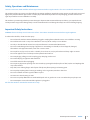
Safety, Operations and Maintenance
Save these instructions. Read and follow all warnings and cautions before using this machine. This unit is intended for commercial use.
This machine will give you many years of trouble-free operating satisfaction, provided it is given proper care. All parts have passed
rigid quality control standards prior to their assembly to produce the nal product. Prior to packaging, your oor machine was
again inspected for assurance of awless assembly.
This machine is protectively packed to prevent damage in shipment. We recommend that upon delivery, you unpack the unit
andinspect it for any possible damage. Only a visual examination will reveal damage that may have occurred during shipping.
Important Safety Instructions
WARNING: Electric shock may occur if used on wet surfaces. Store indoors. Read all instructions before using this appliance.
To reduce the risk of re, electric shock or injury:
• Do not leave the machine unattended when plugged in. Unplug from outlet when not in use and before servicing.
• Do not allow to be used as a toy. Close attention is necessary when used by or near children.
• Use only as described in this manual. Use only manufacturer’s recommended attachments.
• Do not use with damaged cord or plug. If appliance is not working as it should, has been dropped, damaged,
leftoutdoors or dropped into water, return it to a service center.
• Do not pull or carry by cord, use cord as a handle, close a door on cord, or pull cord around sharp edges or corners.
• Do not run appliance over cord. Keep cord away from heated surfaces.
• Do not unplug by pulling on cord. To unplug, grasp the plug, not the cord.
• Do not handle plug or appliance with wet hands.
• Turn o all controls before unplugging.
• Do not put any object into openings. Do not use with any opening blocked; keep free of dust, lint, hair and anything that
may reduce air ow.
• Keep hair, loose clothing, ngers and all parts of body away from openings and moving parts.
• Do not pick up anything that is burning or smoking, such as cigarettes, matches or hot ashes.
• Do not use without vacuum bag and/or lters in place.
• Use extra care when cleaning on stairs.
• Do not use to pick up ammable or combustible liquids such as gasoline or use in areas where they may be present.
• Do not attempt to service the unit while appliance is plugged in.
N.B. This oor machine is intended for commercial use only.

4Parts & Operations Manual Tracker
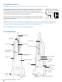
Grounding Instructions
IMPORTANT: Improper grounding method can result in a risk of electrical shock. The machine must be grounded
Electrical equipment must be grounded. If the machine should malfunction or breakdown,
grounding provides a path of least resistance for electrical current to reduce the risk of electric
shock. The Floor Machine is equipped with a cord containing a grounding conductor and
grounding plug. The plug must be inserted into an appropriate outlet that is properly installed
and grounded in accordance with all local codes and ordinances.
If repair or replacement of the cord or plug is necessary, DO NOT connect the grounded wire to
a at bed terminal. The grounding wire is the wire with insulation and an outer green surface,
with or without yellow stripes.
WARNING: Improper connection of the equipment-grounding conductor can result in a risk of electric shock. Check with a qualied
electrician or service person if you are in doubt as to whether the outlet is properly grounded. Do not modify the plug provided with
theappliance. If it will not t the outlet, have a proper outlet installed by a qualied electrician.
NOTE: THIS EQUIPMENT SHALL NOT BE USED WITH ANY EXTENSION CORD.
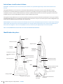
Parts Identication
GROUNDING PIN
BRANCHE DE MISE À LA TERRE
GROUNDED OUTLET
PRISE DE COURANT
GROUNDING INSTRUCTIONS
DIRECTIVES DE MISE À LA TERRE
Handle Grip
Handle Tube
Bag compartment
cover latch
Bag compartment
Self-adjusting
nozzle
Furniture
guard
Power wand
Full bag indicator
On/O switch
Hose Handle
Cord retainer
Thermal reset instructions
Easy-carry handle
Accessory
attachment
opening
Quick cord release
Quick
clean-out
port
Nozzle
hose
Thermal
reset button
Tools
Cord storage hook
Hose hanger

5Parts & Operations Manual Tracker
5Parts & Operations Manual Tracker
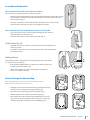
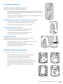
Assembly and Operation
How to Attach the Handle to the Vacuum Cleaner
The vacuum cleaner and the handle are packed separately.
1. After rst removing the handle screw, insert handle into the hole
on top of the vacuum cleaner. Make sure that the cord hook on
the handle is positioned to the back of the vacuum cleaner (Fig. 1).
2. Line up the small hole on the handle with the small hole on the
vacuum cleaner and insert the screw. Make sure the screw is
tightened securely.
How to Attach the Cord to the Retainer Hook on the Handle
1. Create a loop in the power cord, and push it through the slot
and over the hook of the cord retainer (Fig. 3).
2. Pull down on the power cord to remove any slack (Fig. 4).
On/Off Switch (Fig. 5B)
1. To turn the vacuum on, push the switch located on the dust
compartment to the ( I ) position.
2. To turn the vacuum o , push the switch located on the dust
compartment on the ( O ) position.
How to Change the Vacuum Bag
Always operate the vacuum cleaner with a vacuum bag installed. Bags
should be changed when they are 2/3 full.
1. Unplug the vacuum cleaner. Remove the bag compartment cover
and remove the used bag from the bag holder (Fig. 6).
2. Attach the new vacuum bag onto the bag holder (Fig. 7).
3. Pull the bottom corners of the new vacuum bag (Fig. 8).
4. Reinsert the tabs on the end of the bag compartment cover into
the grooves on the bag compartment housing. Press it into place,
and fasten the bag compartment cover latchtightly(Fig. 9).
Fig. 1
Fig. 4
Fig. 2 Fig. 3
Fig. 5
How to Attach the Extension Power Cord to the Cord Lock
1. Connect the extension power cord to the pigtail cord on the
vacuum.
2. Snap the extension power cord into the slot on the end of the
cord lock.
3. Turn the knob on the bottom of the cord lock to tighten the
lock and prevent the cords from pulling apart (Fig. 2).
Full Bag Indicator
The full bag indicator is designed to show when the bag is full or when
there is a clog in the vacuum. (Fig. 5A).
1. If the indicator light illuminates, change the vacuum bag. If
the bag isn’t full, check the hose for a clog.
2. When cleaning with a tool, the indicator light may illuminate.
In this case, continue cleaning.
A)
B)
Fig. 6
Fig. 8
Fig. 7
Fig. 9
Assembly and Operation
How to Attach the Handle to the Vacuum Cleaner
The vacuum cleaner and the handle are packed separately.
• After rst removing the handle screw, insert handle into the hole on top of the vacuum
cleaner. Make sure that the cord hook on the handle is positioned to the back of the
vacuum cleaner (Fig. 1).
• Line up the small hole on the handle with the small hole on the vacuum cleaner
and insert the screw. Make sure the screw is tightened securely.
How to Attach the Cord to the Retainer Hook on the Handle
• Create a loop in the power cord, and push it through the slot and over
the hook of the cord retainer (Fig. 3).
• Pull down on the power cord to remove any slack (Fig. 4).
On/O Switch (Fig. 5B).
• To turn the vacuum on, push the switch located on the dust compartment
to the ( I ) position.
• To turn the vacuum o , push the switch located on the dust compartment
on the ( O ) position.
Full Bag Indicator
The full bag indicator is designed to show when the bag is full or when there
is a clog in the vacuum. (Fig. 5A).
• If the indicator light illuminates, change the vacuum bag. If the bag
isn’t full, check the hose for a clog.
• When cleaning with a tool, the indicator light may illuminate.
In this case, continue cleaning.
How to Change the Vacuum Bag
Always operate the vacuum cleaner with a vacuum bag installed.
Bags should be changed when they are 2/3 full.
• Unplug the vacuum cleaner. Remove the bag compartment cover
and remove the used bag from the bag holder (Fig. 6).
• Attach the new vacuum bag onto the bag holder (Fig. 7).
• Pull the bottom corners of the new vacuum bag (Fig. 8).
• Reinsert the tabs on the end of the bag compartment cover into
the grooves on the bag compartment housing. Press it into place,
and fasten the bag compartment cover latch tightly (Fig. 9)
Quick
clean-out
port
Nozzle
hose

6Parts & Operations Manual Tracker
6Parts & Operations Manual Tracker
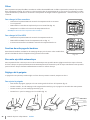
Filters
Your vacuum cleaner is equipped with a secondary and a (High Efficiency) post fi lter. These filters capture fine dust particles and
protect the motor from dirt. Accumulated dirt in the bag compartment will be collected on this filter and may restrict motor
performance. It is important to change the filters regularly — approximately once a year, or as needed.
To Change the Secondary Filter
1. Unplug the vacuum cleaner. Remove the bag compartment cover and remove the bag.
2. Remove the secondary fi lter and replace with a new fi lter (Fig. 10).
3. Replace the bag and bag compartment cover.
NOTE: Neither of the fi lters can be washed and reused.
To Change the Post High Efficiency Filter
1. Unplug the vacuum cleaner. Remove the bag compartment cover.
2. Remove the lter from the front of the bag compartment (Fig. 11).
3. Insert a new filter and replace the bag compartment cover.
Edge Cleaning Feature
For best results when cleaning carpets near walls and stationary furniture, place the right
side ofthevacuum nozzle along the wall or furniture.
Automatic Self-Adjusting Rug Nozzle
The Tracker upright vacuum cleaner is designed with an Automatic Self-Adjusting Rug Nozzle. No manual adjustments are
required. The height of the rug nozzle is instantly and automatically adjusted to carpet pile height. This self-adjusting feature
allows the rug nozzle to oat evenly over all carpet pile surfaces.
Fig. 11
Fig. 10
Fig. 15Fig. 14Fig. 13
Fig. 12
Handle Adjustments
The handle on this vacuum cleaner can be set to one of three positions – upright, middle or low.
To adjust the handle
1. To release the handle, step on the on the left rear corner of the vacuum cleaner nozzle (Fig. 12).
2. Upright position – when cleaning tools are being used or for storage (Fig. 13). Handle locks in this position.
3. Middle position – for normal cleaning (Fig. 14).
4. Low position – for cleaning under furniture (Fig. 15).
Filters
Your vacuum cleaner is equipped with a secondary and a (High Eciency) post lter. These lters capture ne dust particles and
protect the motor from dirt. Accumulated dirt in the bag compartment will be collected on this lter and may restrict motor
performance. It is important to change the lters regularly — approximately once a year, or as needed.
To Change the Secondary Filter
• Unplug the vacuum cleaner. Remove the bag compartment cover and remove the bag.
• Remove the secondary lter and replace with a new lter (Fig. 10).
• Replace the bag and bag compartment cover.
NOTE: Neither of the lters can be washed and reused.
To Change the Post High Eciency Filter
• Unplug the vacuum cleaner. Remove the bag compartment cover.
• Remove the lter from the front of the bag compartment (Fig. 11).
• Insert a new lter and replace the bag compartment cover.
Edge Cleaning Feature
For best results when cleaning carpets near walls and stationary furniture, place the right side
of the vacuum nozzle along the wall or furniture.
Automatic Self-Adjusting Rug Nozzle
The Tracker upright vacuum cleaner is designed with an Automatic Self-Adjusting Rug nozzle.
no manual adjustments are required. The height of the rug nozzle is instantly and automatically
adjusted to carpet pile height. This self-adjusting feature allows the rug nozzle to oat evenly over all carpet pile surfaces.
Handle Adjustments
The handle on this vacuum cleaner can be set to one of three positions – upright, middle or low.
To adjust the handle
• To release the handle, step on the on the left rear corner of the vacuum cleaner nozzle (Fig. 12).
• Upright position – when cleaning tools are being used or for storage (Fig. 13). Handle locks in this position.
• Middle position – for normal cleaning (Fig. 14).
• Low position – for cleaning under furniture (Fig. 15).
6Parts & Operations Manual Tracker
Filters
Your vacuum cleaner is equipped with a secondary and a (High Efficiency) post fi lter. These filters capture fine dust particles and
protect the motor from dirt. Accumulated dirt in the bag compartment will be collected on this filter and may restrict motor
performance. It is important to change the filters regularly — approximately once a year, or as needed.
To Change the Secondary Filter
1. Unplug the vacuum cleaner. Remove the bag compartment cover and remove the bag.
2. Remove the secondary fi lter and replace with a new fi lter (Fig. 10).
3. Replace the bag and bag compartment cover.
NOTE: Neither of the fi lters can be washed and reused.
To Change the Post High Efficiency Filter
1. Unplug the vacuum cleaner. Remove the bag compartment cover.
2. Remove the lter from the front of the bag compartment (Fig. 11).
3. Insert a new filter and replace the bag compartment cover.
Edge Cleaning Feature
For best results when cleaning carpets near walls and stationary furniture, place the right
side ofthevacuum nozzle along the wall or furniture.
Automatic Self-Adjusting Rug Nozzle
The Tracker upright vacuum cleaner is designed with an Automatic Self-Adjusting Rug Nozzle. No manual adjustments are
required. The height of the rug nozzle is instantly and automatically adjusted to carpet pile height. This self-adjusting feature
allows the rug nozzle to oat evenly over all carpet pile surfaces.
Fig. 11
Fig. 10
Fig. 15Fig. 14Fig. 13
Fig. 12
Handle Adjustments
The handle on this vacuum cleaner can be set to one of three positions – upright, middle or low.
To adjust the handle
1. To release the handle, step on the on the left rear corner of the vacuum cleaner nozzle (Fig. 12).
2. Upright position – when cleaning tools are being used or for storage (Fig. 13). Handle locks in this position.
3. Middle position – for normal cleaning (Fig. 14).
4. Low position – for cleaning under furniture (Fig. 15).

7Parts & Operations Manual Tracker
7Parts & Operations Manual Tracker
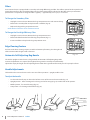
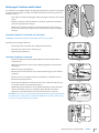
On-Board Tool Cleaning
These vacuums are equipped with on-board cleaning tools including a metal
telescopic power wand, stretch hose, dusting brush and a crevice tool.
1. To use the cleaning tools, lift the hose handle straight up from the vacuum
(Fig. 1).
2. Extend the wand by pulling the button back and pulling the smaller wand
out of the larger wand (Fig. 2).
3. Attach any of the on-board tools to the end of the wand or if you do not
need the wand, any tool can be connected directly onto the hose handle.
How to Replace the Vacuum Belt
CAUTION: Unplug the vacuum cleaner before performing any of these steps.
How to Remove the Bottom Plate
1. Place the vacuum cleaner in the low position by pressing the foot
pedal release twice while reclining the handle. Turn the vacuum over.
2. Slide the clips toward each other (Fig. 3).
3. Remove the bottom plate.
How to Replace the Belt
1. Turn the unit over and remove the bottom plate as described in the above section.
2. Remove the belt guard (Fig. 4). Remove the agitator by pulling it straight out (Fig.
5).
3. Remove the belt from the agitator.
4. Loop a new belt over the motor pulley (Fig. 6) and over the end of the agitator.
5. Stretch the belt over the agitator while inserting it back into the nozzle housing.
6. Reinsert the belt guard.
7. Spin the agitator by hand to make sure it turns smoothly and the new belt is
properly aligned.
8. Replace the bottom plate by hooking the front end of the plate into the two ribs
on
the front end of the nozzle housing. Press the bottom plate into place and fasten it
with the two screws.
NOTE: To ensure maximum cleaning effi ciency, check the belt regularly to ensure it is in good
condition. Replace the belt ifitis stretched, cracked or if excessive slipping is occurring.
Fig. 1 Fig. 2
Fig. 3
Fig. 4
Fig. 5
Fig. 6
On-Board Tool Cleaning
These vacuums are equipped with on-board cleaning tools including a metal
telescopic power wand, stretch hose, dusting brush and a crevice tool.
• To use the cleaning tools, lift the hose handle straight up from
the vacuum (Fig. 1).
• Extend the wand by pulling the button back and pulling the smaller
wand out of the larger wand (Fig. 2).
• Attach any of the on-board tools to the end of the wand or if you
do not need the wand, any tool can be connected directly onto
the hose handle.
How to Replace the Vacuum Belt
CAUTION: Unplug the vacuum cleaner before performing any of these steps.
How to Remove the Bottom Plate
• Place the vacuum cleaner in the low position by pressing the foot
pedal release twice while reclining the handle. Turn the vacuum over.
• Slide the clips toward each other (Fig. 3).
• Remove the bottom plate.
How to Replace the Belt
• Turn the unit over and remove the bottom plate as described in the above section.
• Remove the belt guard (Fig. 4). Remove the agitator by pulling it straight out (Fig. 5).
• Remove the belt from the agitator.
• Loop a new belt over the motor pulley (Fig. 6) and over the end of the
agitator.
• Stretch the belt over the agitator while inserting it back into the nozzle
housing.
• Reinsert the belt guard.
• Spin the agitator by hand to make sure it turns smoothly and the new belt
is properly aligned.
• Replace the bottom plate by hooking the front end of the plate into the two ribs
on the front end of the nozzle housing. Press the bottom plate into place
and fasten it with the two screws.
NOTE: To ensure maximum cleaning e ciency, check the belt regularly to ensure
it is in good condition. Replace the belt if it is stretched, cracked or if excessive
slipping is occurring.

8Parts & Operations Manual Tracker
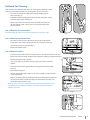
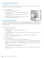
How to Clean the Nozzle Hose
CAUTION : Unplug the vacuum cleaner.
The nozzle hose, located on the back of the vacuum cleaner, carries the dirt from the nozzle to the vacuum bag. If the hose
shouldbecome clogged, there are three di erent access points to check for the clog.
Quick Clean-Out Port
• Remove the wand from the wand/hose holder.
• Squeeze the tabs on both sides of the quick clean-out port and pull away from
the vacuum (Fig. 1)
• Check above and below the port opening for obstructions.
• Remove any obstructions.
• Replace the quick clean-out port by squeezing both tabs and pushing it back
into the wand/hose holder.
Thermal Fuse Protection
Your Tracker vacuum cleaner comes equipped with a Manual Reset Thermal Fuse Protector. This thermal protector is designed to
protect your vacuum cleaner from overheating due to a cuto in airow (i.e. clogged hose, operating the vacuum without a bag).
Should this situation occur, the thermal fuse protector will safely shut o your vacuum cleaner to avoid any potential damage.
To reset the thermal fuse:
• Unplug the vacuum cleaner.
• Check for problem (over-lled bag, clog in hose, clogged lters, etc.).
• Correct problem.
• Locate “tripped” fuse — the small red button located on the bottom of the back side of the main body (roughly one inch
to the right of the left wheel).
• Using a pencil, paper clip, or other pointy object, push the reset button.
• Plug vacuum cleaner in and begin using.
For Best Performance
• Keep machine and all accessories clean and in good operating condition.
• Change vacuum bags and lters as recommended to maintain optimum cleaning eciency.
• Always use genuine vacuum bags, lters and parts, as use of other products may result in poor cleaning or ltration
performance. Our ltration products are designed for maximum performance.
• Have machine checked periodically by a qualied vacuum technician.
• Store machine carefully in dry area.
• For optimum cleaning performance and safety, follow your Owner’s Manual and keep it for future reference.
19Manuel de pièces et d’opérations Tracker
Comment nettoyer le tuyau de buse
ATTENTION : débranchez l’aspirateur.
Le tuyau de buse, situé à l’arrière de l’aspirateur, transporte la poussière de la buse vers le sac ltrant. Si le tuyau est bouché,
ilexiste trois points d’accès di érents pour véri er l’obstruction.
Port de nettoyage rapide
1. Retirez la manche du support manche/tuyau.
2. Pressez les pattes des deux côtés de l’ori ce de nettoyage rapide
et retirez-vous de l’aspirateur (Fig. 1).
3. Véri ez ci-dessus et au-dessous de l’ouverture duport pour les obstructions.
4. Enlevez les obstructions.
5. Remplacez l’ori ce de nettoyage rapide enserrant les deux pattes
et en le renvoyant dans lamanche / le support de tuyau.
Fig. 1
Protection du fusible thermique
Votre aspirateur est équipé d’un protecteur de fusible thermique à réarmement manuel. Ce protecteur thermique est conçu pour
protéger votre aspirateur de la surchaue en raison d’une coupure dans le ux d’air (tuyau obstrué, opérez l’aspirateur sans sac
à poussière). Si cette situation se produit, le protecteur de fusible thermique éteint votre aspirateur en toute sécurité pour éviter
desdommages potentiels.
Pour réinitialiser le fusible thermique :
1. Débranchez l’aspirateur.
2. Vériez le problème (sac rempli, tuyau obstruer, les ltres bouchés, etc.).
3. Corrigez le problème.
4. Localisez le fusible « déclenché » – le petit bouton rouge situé au bas à l’arrière du corps principal (environ un pouce
àladroite de la roue gauche).
5. À l’aide d’un crayon, d’un trombone ou d’un autre objet pointu, appuyez sur le bouton de réinitialisation.
6. Branchez l’aspirateur et commencez à l’utiliser.
Pour la meilleure performance
•Gardez la machine et tous les accessoires propres et en bon état de fonctionnement.
•Changez les sacs à poussière et les ltres comme recommandé an de maintenir une ecacité de nettoyage optimale.
• Utilisez toujours des sacs, des ltres et des pièces d’aspiration authentiques, car l’utilisation de autres produits peut entraîner
de mauvaises performances de nettoyage ou de ltration. Nos produits sont conçus pour une performance maximale.
•Faire vérier périodiquement la machine par un technicien qualié.
•Conservez la machine soigneusement dans un endroit sec.
•Pour une performance et une sécurité de nettoyage optimales, suivez votre manuel d’utilisation et conservez-le pour
consultation ultérieur.

Dustbane Products Ltd., 25 Pickering Pl., Ottawa, ON K1G 5P4 • Tel: 1-800-387-8226 Fax: 1-800-363-5309 www.dustbane.ca
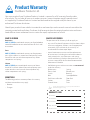
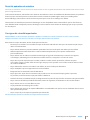
Product Warranty
Dustbane Products Ltd.
Your new product from Dustbane Products Limited is covered by a full warranty from the date
ofpurchase. This includes all new units and accessories (some exceptions apply) manufactured
orsupplied by Dustbane Products Limited and delivered to the original retail purchaserby an
authorizedDustbane distributor.
Should your product have a defect in material or workmanship under normal use and care within the
warranty period outlined below, Dustbane shall arrange to have the original product returned to our
head oce or toan authorized service center for repair, replacement or refund.
WHAT IS COVERED
Reservoirs
ONE (1) YEAR unconditional warranty on all polyethelene
rotational molded reservoirs to be freefromall cracks and/
or corrosion.
Parts
ONE (1) YEAR unconditional warranty on all equipment
parts against defects in material and workmanship under
normal use and care with the exception of any rubber
components and springs.
Labour
ONE (1) YEAR year unconditional warranty on labour
based on Dustbane’s Labour Rates and equipment parts
under normal use and care with theexception of any
rubber components and springs.
EXEMPTIONS
The following products are exempt from this warranty
andalternate conditions may apply:
• Batteries
• Chargers
WHAT IS NOT COVERED
The provisions of this Warranty shall not apply to:
• any unit of Dustbane Equipment which has been subject
to misuse, negligence, accident, use of inappropriate
accessories, parts or chemicals, or serviceby an
unauthorized Dustbane repair depot.
• normal maintenance services and the replacement
of service items (including but not limited to electric
cord, painted parts, any rubber parts and springs,
switch and bearings) made in connection with such
services as required in the Dustbane Recommended
MaintenanceSchedule.
• the following parts and/or accessories are not covered
under the warranty:
Rubber parts Springs
Electric cord Painted parts
Switch Bearings
Belts Squeegee Blades
Pad Drivers or Brushes Floor Pads
Gaskets Filters
External Hoses Fuses
WARRANTY CARD
Model Name:
Model Number:
Serial Number:
Date of Purchase:
Purchased From:
Use this card for quick access to your product information
(information purposes only)

10 Parts & Operations Manual Tracker
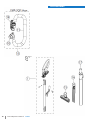
ACCESSORIES

11Parts & Operations Manual Tracker
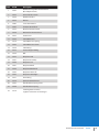
Ref. Part N. Description
1 71211 Looped Handle Assembly
10 71212 Suction Inlet
11 71098 Stretch Hose
13 71073 Quick Draw Hose Assembly
14 71213 Quick Draw Hose Handle
15 71201 Upholstery Tool with Brush
16 71205 Crevice Tool
17 71209 Quick Draw Wand Assembly

12 Parts & Operations Manual Tracker
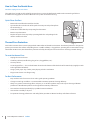
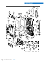
BODY (Front)
MAIN BODY FRONT CMP-3QD.DB
1
2
6
3
11
10
12
13
14
15
19
20
23 24 25
27 28
31
29 28
31
32
27
30
26
33
4
5
7
7
7
8
9
16
17
18
22
21
17
37
36
35
34

13Parts & Operations Manual Tracker
Ref. Part N. Description
1 71214 Power Cord 50’
2 71248 Cord Strain Relief
3 71083 Screw 8/32 x 3/8
4 71065 Wire Harness Cover
5 71215 Motor Cord
6 71080 Wire Bushing
7 71067 Screw Hi Lo #8 x 5/8
8 71072 Thermal Switch Seal
9 71070 Thermal Switch Manual Rest
10 71154 Motor Compartment Bushing
11 71057 Secondary Filter
11 71216 Secondary Filter (Bulk)
12 71217 Motor Cover Seal Kit
13 71218 Motor Cover (Black Replacement)
14 71219 Exhaust Filter Foam
15 71069 Post Filter with Frame
15 71220 Post Filter with Frame (Bulk)
16 71062 Dust Cover Latch Spring
17 71206 Dust Cover Latch w/ Spring
18 71202 Dust Cover Assembly (Black Replacement)
19 71221 Paper Bag (3 Pack)
19 71060 Paper Bag (12 PACK)
20 71059 Dust Compartment Seal
21 71064 Switch Cover Seal
22 71055 Switch Cover
23 71053 Cord Restraining Strap
24 71106 Handle Fitting
25 71052 On/O Switch
26 71222 Wheel Axle Assembly
27 71223 Rear Wheel 59mm
28 71224 Nylon Washer 25mm
29 71076 E Clip 5mm
30 71077 Rear Wheel Axle
31 71082 Axle Clamp
32 71078 Axle Flat Screw
33 71210 Dust Compartment
34 71225 Extension Cord
35 71226 Pressure Switch Mount
36 71227 Pressure Switch

14 Parts & Operations Manual Tracker
MAIN BODY FRONT CMP-3QD.DB
1
2
6
3
11
10
12
13
14
15
19
20
23 24 25
27 28
31
29 28
31
32
27
30
26
33
4
5
7
7
7
8
9
16
17
18
22
21
17
37
36
35
34
BODY (Front)

15Parts & Operations Manual Tracker
Ref. Part N. Description
36 71227 Pressure Switch
37 71228 Full Bag Indicator
35, 36,
37 71208 Full bag indicator assembly

16 Parts & Operations Manual Tracker
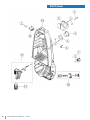
BODY (Back)

17Parts & Operations Manual Tracker
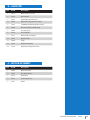
Ref. Part N. Description
1 71089 Handle Screw
2 71083 Screw 8/32 x 3/8
3 71090 Hose Hanger
4 71086 Bag Inlet
5 71085 Suction Inlet Gasket
6 71229 Upholstery Tool Clip
7 71230 Crevice Tool Holder
10 71091 Pressure Relief Valve
11 71231 Lower Wand Holder and Cord Hook
13 71232 Upper Wand Holder
14 71210 Dust Compartment
15 71092 Clean Out Cu

18 Parts & Operations Manual Tracker
28
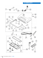
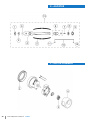
D - NOZZLE ASSY

19Parts & Operations Manual Tracker
Ref. Part N. Description
1 71203 Nozzle Housing with Furniture Guard
(Black Replacement)
2 71233 Hose Inlet Tube Screw
3 71234 Nozzle Inlet Tube
5 71235 Washer
6 71067 Screw HI Lo #8x5/8
7 71207 Furniture Guard Clear
8 71152 Rivet for Furniture Guard
9 71236 Washer for Furniture Guard
10 71237 Pedal Frame
11 71185 Swivel Belt Cover
12 71170 Swivel Belt Cover Spring
13 71169 Swivel Belt Cover Screw
14 71158 Felt Packing
15 71159 Vented Support Fitting
16 71238 Belt
17 71239 Baseplate Stud
18 71161 Baseplate Assembly
19 71240 Baseplate Seal
20 71241 Baseplate Wheel
21 71164 Baseplate Wheel Axle
22 71242 Baseplate Latch Left
23 71243 Baseplate Latch Right
24 71151 Hose Fitting
25 71150 Quick Draw Nozzle Hose
26 71167 Handle Release Spring Screw
27 71166 Handle Release Spring
28 71176 "Metal Agitator Assembly
*Agitator Schematic on Next Page*"

20 Parts & Operations Manual Tracker
E – AGITATOR
F – MOTOR ASSEMBLY
La page charge ...
La page charge ...
La page charge ...
La page charge ...
La page charge ...
La page charge ...
La page charge ...
La page charge ...
La page charge ...
La page charge ...
La page charge ...
La page charge ...
-
 1
1
-
 2
2
-
 3
3
-
 4
4
-
 5
5
-
 6
6
-
 7
7
-
 8
8
-
 9
9
-
 10
10
-
 11
11
-
 12
12
-
 13
13
-
 14
14
-
 15
15
-
 16
16
-
 17
17
-
 18
18
-
 19
19
-
 20
20
-
 21
21
-
 22
22
-
 23
23
-
 24
24
-
 25
25
-
 26
26
-
 27
27
-
 28
28
-
 29
29
-
 30
30
-
 31
31
-
 32
32


Dustbane Tracker Operations Manual
- Catégorie
- Aspirateurs
- Taper
- Operations Manual
dans d''autres langues
- English: Dustbane Tracker