Hobart HL1400C Manuel utilisateur
- Catégorie
- Mélangeurs
- Taper
- Manuel utilisateur
Ce manuel convient également à

701 S. RIDGE AVENUE TROY, OHIO 45373
937-332-3000 · WWW.HOBARTCORP.COM
Models
HL800 ML-141074
HL800 ML-141100
HL800C ML-141077
HL1400 ML-141078
HL1400 ML-141099
HL1400C ML-141081
HL1400N ML-141111
HL1400N ML-141113
HL1400N ML-141114
HL1400N ML-141202
HL1400N ML-141204
INSTRUCTION
MANUAL
FORM 45236 Rev. C (June 2020)
®

– 2 –
LEGACY
®
80-QUART AND 140-QUART MIXERS
© HOBART, 2020

– 3 –
TABLE OF CONTENTS
GENERAL ............................................................................................................................................. 4
Safety Guidelines ............................................................................................................................ 4
Operation Guidelines ....................................................................................................................... 4
Dust Hazard ................................................................................................................................... 5
Warning Symbol .............................................................................................................................. 5
Warranty .......................................................................................................................................... 5
General Information ......................................................................................................................... 5
INSTALLATION .................................................................................................................................... 6
Unpacking ........................................................................................................................................ 6
Location ........................................................................................................................................... 6
Electrical Connections ..................................................................................................................... 7
Initial Checks ................................................................................................................................... 7
OPERATION ........................................................................................................................................ 8
Standard Controls ............................................................................................................................ 9
Bowl Placement ............................................................................................................................. 10
Agitator .......................................................................................................................................... 10
Power Bowl Lift ...............................................................................................................................11
Prepare for Mixing ..........................................................................................................................11
Timer Operation ............................................................................................................................. 12
Operating Notes ............................................................................................................................ 13
Unloading BOWL ........................................................................................................................... 13
Wire Cage (Fig. 9) ......................................................................................................................... 14
Agitators ........................................................................................................................................ 14
CLEANING ......................................................................................................................................... 15
MAINTENANCE ................................................................................................................................. 16
Interlock Safety System ................................................................................................................. 16
Lubrication ..................................................................................................................................... 17
Adjustments ................................................................................................................................... 18
Transmission Belt .......................................................................................................................... 19
TROUBLESHOOTING ...................................................................................................................... 20
Service ........................................................................................................................................... 20
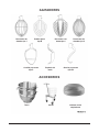
AGITATORS ....................................................................................................................................... 21
ACCESSORIES ................................................................................................................................. 21

– 4 –
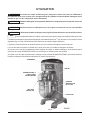
Installation, Operation and Care of
Legacy
®
80-Quart Mixers
and
Legacy
®
140-Quart Mixers
SAVE THESE INSTRUCTIONS
GENERAL
SAFETY GUIDELINES
• All operators must be properly trained in the safe operation of the mixer and attachments.
• To avoid risk of serious injury follow all precautions and instructions in this manual when installing,
operating, and servicing the mixer.
• To avoid risk of serious injury, keep hands, feet, clothing and utensils away from the bowl, bowl support,
slideways, and agitator when the mixer is in operation or any of the components are moving.
• Do not operate the mixer if it is not in proper operating condition.
• Disconnect power to the mixer and follow lockout-tagout procedures before moving or servicing the
mixer.
• Do not operate the mixer if parts are disassembled.
• Do not override safety switches on the mixer.
• When moving the mixer make sure it is stable to avoid tipping and keep hands and feet clear of the
bottom of the mixer to avoid pinching.
• Use the STOP button to stop the mixer. Never open the wire cage or use the power bowl lift to stop
the mixer.
• Do not wear loose clothing around the mixer.
• Donotinhaledustparticlesfrommixingingredients.Exposuretodust(includingour)maybeharmful
to health. When mixing ingredients that develop dust use the STIR speed until the dust is eliminated
and follow the instructions in the DUST HAZARD section below.
• Do not install or leave an agitator on the mixer without a bowl in place.
• Donotuseexcessiveforcewhenoperating,whichcouldaectthestabilityofthemixer.
OPERATION GUIDELINES
• Use the correct sized bowl only with agitators for that sized bowl. Double check the sizes when using
a reduced sized bowl.
• Ensurethebowl,agitatorandwirecagearecorrectlyttedtothemixer.
• Stop the mixer before adding more ingredients unless using a food chute.
• Have your mixer regularly serviced; at least twice a year for typical usage. Mixers may require more
or less service depending on frequency of use.
• Use the mixer in a well-lit area.

– 5 –
• Ensure this manual is kept in an easily accessible place near the mixer for future reference.
• Do not clean the mixer with scouring powder or a scouring pad.
• Do not clean aluminum agitators in dishwashers.
• Do not hose or pressure clean the mixer. It is important to adhere to the cleaning instructions detailed
in the CLEANING section of the manual.
DUST HAZARD
In order to minimize any dust hazard, follow the instructions detailed below.
Whenmixingingredientscaremustbetakentoavoidtheinhalationofdustparticlese.g.our.Reference
should be made to the product supplier’s data sheets to ensure adequate precautions and protections
are taken.
Ingredientssuchasourmustbeaddedcarefullytominimizeair-bornedustparticles.
Carefully slit the bag while holding it in the lower part of the bowl. When mixing dry ingredients use the
lowest speed and a splash cover to minimize dust emission. Mix the ingredients in the bowl using the
lowest speed until the risk of producing any dust is eliminated. Fit suitable dust extraction equipment.
WARNING SYMBOL
To identify the safety messages in this manual, the following symbol has been used.
The WARNING symbol is located in the manual before the corresponding
information to ensure safe use of the mixer.
WARRANTY
Installationsandrepairscarriedoutbynon-authorizedservicetechniciansmayaectthemixerwarranty.
Usingotherthanoriginalreplacementpartsmayaectthemixerwarranty.Technicalalterationstothe
mixermayaectthemixerwarranty.
For warranty information, please contact Hobart Customer Care.
GENERAL INFORMATION
Hobart reserves the right to alter the design of its products without prior notice. If you have questions
regardingmixerdetailsnotincludedinthismanual,contactyourlocalHobartServiceOce.

– 6 –
INSTALLATION
UNPACKING
This mixer was inspected before leaving the factory. The carrier assumes full responsibility for the safe
delivery of the mixer upon acceptance of the mixer for shipping. The customer must check for possible
shipping damage immediately upon receipt before moving, installing, or modifying the mixer.
If damage is found, keep all original packing materials for inspection purposes. The customer must complete
the following steps to report the damage;
1.Carrier'slocalterminalmustbenotiedwithin5businessdaysofshipmentreceipt(notetime,date,
andwhowasspokento),andfollowupandconrmwithwrittenorelectroniccommunication.
2. Notify Hobart customer care at (800) 333-7447 within 5 business days of shipment receipt.
Priortoinstallation,testtheelectricalservicetoassurethatitcomplieswiththespecicationsonthe
machine data plate.
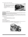
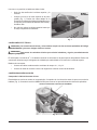
LOCATION
Place the mixer in its operating location. Allow adequate space around the mixer for the user to operate
the controls and install and remove the bowls. The area above and to the right side of the mixer should
allow the top and side covers to be removed for routine maintenance and servicing. Select a suitable
atandlevelsurfacethatcansupporttheweightofthemixerandcontentsofafullbowl.Inareaswhere
stabilitymightbeanissue,themixershouldbesecuredtotheoorasfollows:
Thismixercanbeboltedtotheoorusingstuds.Flooranchoringhardwareisincludedwithsomemodels.
Mixers without anchoring hardware do not need to be anchored.
a. Place the mixer in its operating location.
b. Marktheoorbyusingthefourholesinthemixerbaseasatemplate.
c. Movethemixerforaccesstotheoor.
d. Using a
5
/8"diameterbit,drillfourholesintheoortoadepthof2".
e. Driveooranchorsushwiththesurfaceoftheconcrete.
f. Expand the anchor with the setting tool provided. The anchor is properly expanded when the
shoulderofthesettingtoolisushwiththetopoftheanchor.
g. Return the mixer to its operating location over the drilled holes.
h. Installthestudsthroughthebaseandintotheooranchors.
i. Level according to the leveling instructions on the next page.
j. Installatwashers,lockwashers,andnutsontothestudsandtighten.
k. Sawoallthreadsushwiththetopofthenutandremoveanysharpedges.

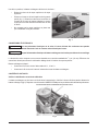
– 7 –
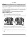
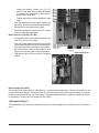
Onceinposition,themixermustbeleveled:
• Remove the two top cover screws and the top
cover.
• Place a level on the top rim of the large pulley
(Fig. 1). Slide shims under the base contact
surface of the mixer as required to level it front-
to- back and side-to-side.
• Do not replace the top cover until installation is
completed.
ELECTRICAL CONNECTIONS
Electrical and grounding connections must comply with the applicable sections of
the National Electrical Code and other local electrical codes.
Disconnect the electrical power to the mixer and follow lockout / tagout procedures.
A hole for
3
/4"-trade-size conduit is located at the top of the pedestal. Make electrical connections per the
wiring diagram located on the inside of the top cover.
Three-phasemixer:
• ConnecteldsupplyleadwirestoL1,L2andL3.
• Connect ground wire to ground lug on the mixer.
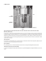
INITIAL CHECKS
Check Lubrication Before Use
This mixer is shipped with oil in the transmission. Check the oil level before starting the mixer (Fig. 2).
Refer to the LUBRICATION section for applicable lubrication procedures.
Fig. 1
Fig. 2

– 8 –
Fig. 3
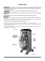
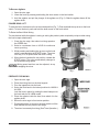
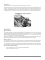
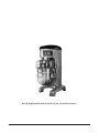
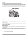
OPERATION
To avoid risk of serious injury, keep hands, feet, clothing, and utensils away from
the bowl, bowl support, slideways, and agitator when the mixer is in operation or when any of the
components are moving.
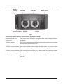
This food mixer is only for professional use by properly trained persons.
Ensure operators have read and understood this manual and have received proper
training.
Do not use the mixer without the interlocked bowl wire cage in place.
For the HL800C and HL1400C models, follow all instructions for the HL800 and HL1400 models.
Legacy® mixers are equipped with SmartTimer
TM
controls and a power bowl lift. Other operating parts
(Fig. 3) and their functions are described throughout the Operation section.
The wire cage must be in position or the mixer will not operate.
The bowl must stay in the locked position on the bowl support or the mixer will not operate.
If the bowl support is not raised all the way up (mix position), the mixer will not operate unless the START
button is pressed and held.
If the bowl support is not raised to the mix position, when the START button is pressed and held, the mixer
will operate only in STIR speed.

– 9 –
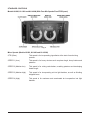
STANDARD CONTROLS
Models HL800, HL1400 and HL1400N (With Four Mix Speeds Plus STIR Speed)
Mixer Speeds (Models HL800, HL1400 and HL1400N)
STIR (Slow) This speed is for incorporating ingredients at the start of each mixing
process.
SPEED 1 (Low) This speed is for heavy mixtures such as pizza dough, heavy batters and
potatoes.
SPEED 2 (Medium-low) This speed is for mixing cake batters, mashing potatoes and developing
bread dough.
SPEED 3(Medium-high) Thisspeedisforincorporatingairintolightbatches,aswellasnishing
whipped items.
SPEED 4 (High) This speed is for maximum and accelerated air incorporation into light
batches.
Fig. 4

– 10 –
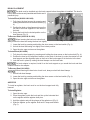
BOWL PLACEMENT
The bowl must be installed onto the bowl support before the agitator is installed. The bowl is
heavy and must be correctly handled and lifted to avoid
personal injury.
To Install Bowl (HL800 & HL1400)
1. Fully lower the bowl support by pressing and
holding the down arrow on the bowl switch (Fig
4).
2. Position the bowl so the alignment pins on the
leftsideofthebowlsupporttintheholesin
the bowl.
3. Swing the bowl into the locked position on the
bowl support (Fig. 5).
To Remove Bowl (HL800 & HL1400)
Before lowering the bowl onto a bowl truck,
always unlock the bowl and swing the bowl out slightly.
1. Lower the bowl by pressing and holding the down arrow on the bowl switch (Fig. 4).
2. Unlock the bowl and swing out slightly from locked position.
3. Open the wire cage and remove the agitator.
To Install Bowl (HL1400N)
1. Fully lower the bowl support by pressing and holding the down arrow on the bowl switch (Fig. 4).
2. Position the bowl so the alignment bracket on the back of the bowl is under the retainer on the
bowlsupportandthealignmentpinsonthefrontofthebowlsupporttintheholesinthebowl.
3. Lock the bowl in place by rotating the bowl clamps over the bowl tabs.
If a bowl adapter is required, install it on the bowl support as you would the bowl and then
install the bowl on the adapter.
To Remove Bowl (HL1400N)
Before lowering the bowl onto a bowl truck, always unlock both bowl clamps.
1. Unlock both bowl clamps.
2. Lower the bowl by pressing and holding the down arrow on the bowl switch (Fig. 4).
3. Open the wire cage and remove the agitator.
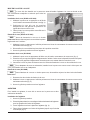
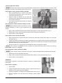
AGITATOR
To install an agitator, the bowl must be on the bowl support and fully
lowered.
To Install Agitator
1. Open the wire cage.
2. Place the agitator inside the bowl and line up the horizontal slot
on the agitator with the agitator shaft pins.
3. Hold the agitator and pull the plunger of the agitator out (Fig. 6).
4. Slide the agitator up the agitator shaft until it stops and latches
(Fig. 5).
Fig. 6
Fig. 5

– 11 –
To Remove Agitator
1. Open the wire cage.
2. Lower the bowl by pressing and holding the down arrow on the bowl switch.
3. Holdtheagitatorandpulltheplungeroftheagitatorout(Fig.6).Slidetheagitatordownothe
agitator shaft.
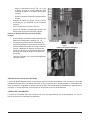
POWER BOWL LIFT
To raise the bowl, the bowl must be in the locked position (Fig. 7). Push and hold the up arrow on the bowl
switch. To lower the bowl, push and hold the down arrow on the bowl switch.
To Raise the Bowl While Mixing
To raise the bowl while the agitator is mixing or stirring the product (when required by recipe or when using
thebowlscraperattachment):
1. Close the wire cage, then select a mixing speed on
the SPEED dial.
2. Select a count-down time or HOLD for continuous
count-up mixing.
3. While pressing and holding the up arrow on the bowl
switch, press and hold the START button. The mixer
runs only in STIR speed while the bowl is rising.
4. When the bowl reaches the mix position, release the
START button. The mixer automatically changes to
the selected mixing speed.
Mixing speed and time can be adjusted, at any
time without stopping the mixer.
Fig. 8
PREPARE FOR MIXING
1. Open the wire cage.
2. Place the mixing bowl on the bowl support.
3. Pour the ingredients into the bowl.
4. Swing the bowl back to the locked position for HL800 &
HL1400.
Lock the bowl in place by rotating the bowl clamps over
the bowl tabs for HL1400N model.
5. Place the agitator inside the bowl, then attach it to the
agitator shaft.
6. Return the wire cage to front-center position.
7. Push and hold the up arrow on the bowl switch until the
bowl reaches the mix position and stops.
8. The mixer is now ready for mixing. (See Timer Operation.)
Fig. 7

– 12 –
TIMER OPERATION
Using the Count-Up Mode (Continuous Mixing)
1. Turn the SPEED dial to select a mix speed (the SPEED setting can be changed at any time during
mixing).
STIR should be used to incorporate ingredients. Do not use STIR to develop dough products.
2. Set the timer on hold by turning the TIME selector counterclockwise until "Hold" appears in the
TIME window.
3. PresstheSTARTbuttontobeginmixing.Thetimerstartstocountupfrom00:00.
If the wire cage is opened at any time, mixing will stop. To resume mixing, close the wire cage
and press the START button.
4. Press the STOP button to stop mixing; the elapsed mixing time is displayed in the TIME window.
5. Press the START button to resume mixing if needed.
Whenthetimerreaches20:00minutes,itwillrolloverto00:01andcontinuetocountupuntil
the STOP button is pressed.
Using the Count-Down Mode (Timed Mixing) (HL800 and HL1400 models)
1. Turn the SPEED dial to select a mix speed.
a. If the count-up mode was used for the previous batch, the desired time must be entered.
b. If the count-down mode was used for the previous batch, the previous time will be displayed.
Ifadierenttimeisrequired,turntheTIMEselectortothedesiredtime.
2. Press the START button to begin mixing. The timer starts to count down from the set time.
a. To stop the mixing at any time, press the STOP button. To resume mixing, press the START
button.Forexample:ThemixerisstartedatSPEED1for30secondsandisstoppedafter
10 seconds. Pressing the START button will resume the mixing operation for the remaining 20
seconds.
b. If the mixer is stopped and a new time setting is entered, pressing the START button saves
thenewtimesettingonthe currentspeedselection.Forexample:Themixerisstartedat
SPEED 1 for 30 seconds and is stopped after 10 seconds. A new time is entered by turning the
TIME selector. The new time will replace the initial 30 seconds for SPEED 1 after the START
button is pressed.
c. If the time is changed while mixing, the mixer will operate until the new time expires. The
adjustment to the time will not be stored.
d. If the mix speed is changed while mixing, the time will revert to the previously set time for the
selected speed and count down.
The agitator does not stop immediately. To avoid risk of serious injury, keep hands,
clothing, and utensils out of the mixing bowl and away from the agitator as the agitator winds down.
If the wire cage is opened at any time, mixing will stop. To resume mixing, close the wire cage
and press the START button.
3. Whenthetimerreaches00:00,themixerwillstopandabeepersoundsfor3seconds.Thecount-
down timer will display the last-entered time.

– 13 –
Using the Count-Down Mode (Timed Mixing) (HL1400N model)
1. Turn the SPEED dial to select a mix speed.
a. Enter the desired time.
2. Press the START button to begin; the timer starts to count down from the set time.
a. To stop mixing at any time, press the STOP button. To resume mixing, press the START button.
Forexample:ThemixerisstartedatSPEED1for30secondsandisstoppedafter10seconds.
Pressing the START button will resume the mixing operation for the remaining 20 seconds.
b. If the mixing is stopped and a new time setting is entered, the timer will count down from the
new time.
c. If the time is changed while mixing, the mixer will operate until the new time expires.
d. If the mix speed is changed while mixing, the time will continue to count down.
The agitator does not stop immediately. To avoid risk of serious injury, keep hands,
clothing, and utensils out of the mixing bowl and away from the agitator as the agitator winds down.
If the wire cage is opened at any time, mixing will stop. To resume mixing, close the wire cage
and press the START button.
3. Whenthetimerreaches00:00,themixerwillstopandabeeperwillsoundfor3seconds.The
count-down timer will display the last-entered time.
OPERATING NOTES
• STIR should be used for incorporating ingredients. Do not use it to develop dough products.
• If the mixer is stopped during a mixing operation, the timer will stop. The timer will resume
whereitleftowhentheSTARTbuttonispressed.
• The SPEED window will display the current SPEED selection.
• Turn the TIME selector clockwise to take the mixer out of the hold mode.
UNLOADING BOWL
1. After the mixer has stopped, and the agitator has come to rest, for Models HL800 and HL1400,
unlock the bowl and swing-out slightly. For HL1400N, rotate both bowl clamps to the unlocked
position. Press and hold the down arrow on the bowl switch to lower the bowl.
2. Open the wire cage assembly.
3. Remove the agitator from the agitator shaft.
4. Remove the bowl from the bowl support.

– 14 –
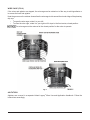
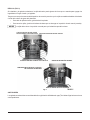
WIRE CAGE (FIG. 9)
If the mixer and agitator are stopped, the wire cage can be rotated out of the way to add ingredients or
to access the bowl and agitator.
Note the grooves on the retainer shoes allow the wire cage to ride around the circular ridge of the planetary
drip cup.
• To open the wire cage, rotate it to your left.
• To close the wire cage, rotate it to your right until it stops in the front-center, closed position.
The wire cage must be returned to the closed position for the mixer to operate.
AGITATORS
Agitators are covered in a separate Hobart Legacy
®
Mixer Use and Application Handbook. Follow the
instructions accordingly.
Fig. 9

– 15 –
CLEANING
Disconnect the electrical power to the mixer and follow lockout / tagout procedures.
New mixing bowls and accessories (beaters, whips and dough arms) should be thoroughly washed with
hot water and a mild soap solution, rinsed with either a mild soda or vinegar solution and thoroughly rinsed
with clear water before use. This cleaning procedure should be followed for bowls and agitators before
whipping egg whites or whole eggs.
The mixer should be thoroughly cleaned daily. Do not use a hose or pressure clean the mixer; it should
be washed with a clean, damp cloth. The base allows ample room to clean under the mixer. The apron
(Fig. 3) may be removed for cleaning by loosening the thumb screws. Do not wipe down the slideways
(Fig. 11) when cleaning. Do not clean the mixer with scouring powder or a scouring pad. Do not clean
aluminum agitators in dishwasher.
The drip cup-splash guard assembly (Fig. 3) should be removed periodically and wiped clean.
Remove and Clean Wire Cage (Fig. 10)
1. Lower the bowl. Remove the agitator and then remove the bowl.
2. While holding the wire cage securely with both hands, rotate it to your left until the front-center
retainer shoe reaches the gap in the circular ridge of the planetary drip cup.
3. Lower the front of the wire cage and move it slightly to the rear until the rear retainer shoes clear
the ridge of the drip cup. The wire cage can now be removed.
Fig. 10
4. Wash the wire cage in a sink, rinse with clear water, and dry with a clean cloth.
5. The stainless steel splash guard can be washed with a cloth or sponge using warm, soapy water.
Rinse with clear water and dry with a clean cloth.
Reinstall Wire Cage
1. Position the ring of the wire cage so the front-center retainer shoe is positioned below the gap in
the circular ridge of the planetary drip cup.
2. Position the grooves so the rear retainer shoes straddle the circular ridge on the planetary drip
cup.

– 16 –
3. Lift the front of the wire cage so the front-center retainer shoe passes up through the gap in the
circular ridge on the planetary drip cup.
4. Rotate the wire cage to your right until all three retainer shoes straddle the ridge on the drip cup.
5. Continue rotating the wire cage to position the opening to the front of the mixer (to install the
agitators) or until it stops at the front-center position.
MAINTENANCE
Disconnect the electrical power to the mixer and follow lockout / tagout procedures.
Do not remove any covers or loosen any ttings while the mixer is operating. Ensure
the electrical supply has been isolated before attempting to service or move the mixer.
The electronic drive control is tted with high voltage capacitors. Isolate the mixer
from the mains and allow the capacitors to discharge for 5 minutes before removing any covers.
Only Hobart trained service personnel or other properly trained and qualied
personnel should carry out service.
INTERLOCK SAFETY SYSTEM
Regular inspection of the mixer's safety system is necessary to check the operation of the wire cage and
bowl support interlock switches. Inspections must be performed no less than once a year.
A spare parts manual is available from Hobart Resource Center. For continued safe and reliable operation
of this mixer, it is recommended that servicing is only carried out by Hobart trained service personnel.

– 17 –
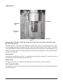
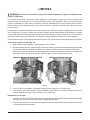
LUBRICATION
AGITATOR
SHAFT
Fig. 11
Slideway (ML-141100, ML-141099, ML-141114, ML-141074, ML-141077, ML-141078, ML-141081,
ML-141111, ML-141113)
The slideways (Fig. 11) should be lubricated approximately twice a year. To reach these areas, fully lower
the bowl support and remove the apron (Fig. 3), which is secured by thumb screws. Wipe a thin coat of
Lubriplate 630AA on the bowl pad area of the bowl supports and on each slideway. Install the apron (Fig. 3).
Certain units contain polymer, slideway inserts which do not require lubrication. For ML-141202 and ML-
141204 do not lubricate.
Planetary Seal
Occasionally, the planetary seal (Fig. 11) may become dry and begin to squeak. To correct this, work a
little lubrication (mineral oil) under the lip of the seal.
Agitator Shaft
The agitator shaft (Fig. 11) should be lubricated twice a year with a thin coat of mineral oil.
Bowl Clamps (HL1400N)
The bowl clamp area of the bowl support should be lubricated with a thin coat of Lubriplate 630AA two to
three times per year.

– 18 –
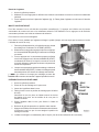
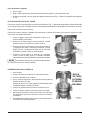
Transmission
Electrically isolate the mixer and follow proper lock out tag out procedures.
To check the oil level, remove the top cover, which is secured by two screws. Remove the Transmission Fill
Plug (Fig. 12) and check the oil level. If the oil level is below the line on the oil dipstick, add a small amount
oftherecommendedtransmissionoiluntilitreturnstotheproperlevel.Donotoverllthetransmission,
asleakagemayresult.ContactyourlocalHobartServiceocefortherecommendedtransmissionoil.
Fig. 12
ADJUSTMENTS
Agitator Clearance
The agitator clearance should be checked periodically. The agitator must not touch the bowl, and the
maximumclearancebetweenthebottomofthebowlandtheBatbeateris
1
/8" (3 mm); the maximum
clearance between the bottom of the bowl and the ED dough arm is
5
/16" (8 mm) for the HL800 Mixer
and
11
/16" (17 mm) for the HL1400 and HL1400N models.
Install a bowl and agitator (e.g., beater). If the bowl and beater come into contact before the bowl support
reaches its stop, adjust the stop screw. Refer to Adjust the Bowl/Agitator Clearance, below
Measure Clearance
Pourenoughourintothebowltocoverthebottomofthebowlwherethebeatertravels.Withthebowl
fullyraised(beatershouldnottouchthebottomofthebowl),brieyrunthemixeratthelowestspeed.
Turnothemixer,disconnecttheelectricalpowersupply,andmeasurethedepthofourwherethebeater
has traced a path. This measurement should be taken at several points around the bowl to ensure accuracy.
Adjust the Bowl/Agitator Clearance
• Remove the apron (Fig. 3) (which is secured by thumbscrews).
• Adjust the stop screw on left side.

– 19 –
- Loosen the bottom locking nut, (Fig. 13)
and turn the stop screw counterclockwise
to increase the clearance or clockwise to
decrease the clearance.
- Tighten the locking nut while holding the stop
screw.
• After the adjustments are made, replace the
apron (Fig. 3) and secure it with the thumbscrews.
• Reconnect the electrical power supply.
• Carefully operate the power bowl lift several
times to check the adjustment.
Bowl Lock Lever (HL800, HL1400)
• Occasionally debris may collect and cause the
lever (Fig. 14) to move slowly.
• Pourverywarmwateraroundlockpintoush
out food particles that may have collected there.
Thewatershouldowthrough,aroundthepin.
Be sure to have a cloth or dish under to bowl
support to catch the water and food particles.
• Lubricate the pin with a thin coat of Lubriplate
630AA.
Bowl Clamps (HL1400N)
The height of the bowl clamp is controlled by a spring washer and locknut, which are located on the
bottom of the bowl support. Turning the lock nut counterclockwise will loosen the bowl clamp, turning the
locknut clockwise will tighten the bowl clamp. If repeated adjustments are necessary, additional service
isnecessary.ContactyourlocalHobartServiceOce.
TRANSMISSION BELT
The transmission belt should be inspected yearly for wear and replace by a Hobart Service Technician if
worn.
Fig. 14
Bowl Lock Lever
Fig. 13

– 20 –
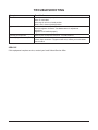
TROUBLESHOOTING
Symptoms Possible Causes
Mixer will not start. Circuit protector is in open position - check fuse or disconnect switch.
Mixer is overloaded.
Wire cage is not in the closed position.
Bowl is not in closed (locked) position.
Agitator touches bowl. Bowl is not in closed (locked) position.
Improper agitator clearance - see Maintenance for adjustment
procedure.
Agitator is not installed properly.
Planetary seal squeaks. Seal requires occasional lubrication - see Maintenance.
Timer displays error code (ErXX). Iftheerrorcodeisashing-disconnectelectricalpowerfrommixerfor1
minute, then reconnect. If symptoms still exist, contact your local Hobart
Serviceoce.
SERVICE
Ifthisequipmentrequiresservice,contactyourlocalHobartServiceoce.
La page est en cours de chargement...
La page est en cours de chargement...
La page est en cours de chargement...
La page est en cours de chargement...
La page est en cours de chargement...
La page est en cours de chargement...
La page est en cours de chargement...
La page est en cours de chargement...
La page est en cours de chargement...
La page est en cours de chargement...
La page est en cours de chargement...
La page est en cours de chargement...
La page est en cours de chargement...
La page est en cours de chargement...
La page est en cours de chargement...
La page est en cours de chargement...
La page est en cours de chargement...
La page est en cours de chargement...
La page est en cours de chargement...
La page est en cours de chargement...
La page est en cours de chargement...
La page est en cours de chargement...
La page est en cours de chargement...
La page est en cours de chargement...
La page est en cours de chargement...
La page est en cours de chargement...
La page est en cours de chargement...
La page est en cours de chargement...
La page est en cours de chargement...
La page est en cours de chargement...
La page est en cours de chargement...
La page est en cours de chargement...
La page est en cours de chargement...
La page est en cours de chargement...
La page est en cours de chargement...
La page est en cours de chargement...
La page est en cours de chargement...
La page est en cours de chargement...
La page est en cours de chargement...
La page est en cours de chargement...
La page est en cours de chargement...
La page est en cours de chargement...
La page est en cours de chargement...
La page est en cours de chargement...
La page est en cours de chargement...
La page est en cours de chargement...
La page est en cours de chargement...
La page est en cours de chargement...
-
 1
1
-
 2
2
-
 3
3
-
 4
4
-
 5
5
-
 6
6
-
 7
7
-
 8
8
-
 9
9
-
 10
10
-
 11
11
-
 12
12
-
 13
13
-
 14
14
-
 15
15
-
 16
16
-
 17
17
-
 18
18
-
 19
19
-
 20
20
-
 21
21
-
 22
22
-
 23
23
-
 24
24
-
 25
25
-
 26
26
-
 27
27
-
 28
28
-
 29
29
-
 30
30
-
 31
31
-
 32
32
-
 33
33
-
 34
34
-
 35
35
-
 36
36
-
 37
37
-
 38
38
-
 39
39
-
 40
40
-
 41
41
-
 42
42
-
 43
43
-
 44
44
-
 45
45
-
 46
46
-
 47
47
-
 48
48
-
 49
49
-
 50
50
-
 51
51
-
 52
52
-
 53
53
-
 54
54
-
 55
55
-
 56
56
-
 57
57
-
 58
58
-
 59
59
-
 60
60
-
 61
61
-
 62
62
-
 63
63
-
 64
64
-
 65
65
-
 66
66
-
 67
67
-
 68
68


Hobart HL1400C Manuel utilisateur
- Catégorie
- Mélangeurs
- Taper
- Manuel utilisateur
- Ce manuel convient également à
dans d''autres langues
- English: Hobart HL1400C User manual
- español: Hobart HL1400C Manual de usuario
Documents connexes
-
Hobart HL1400N Mode d'emploi
-
Hobart ML-141105 Manuel utilisateur
-
 Centerline CENTERLINE HMM20 Manuel utilisateur
-
-
-
Hobart LEGACYHL200 Manuel utilisateur
-
-
-
-

