
DOC023.97.80367
APA 6000
05/2013, Edition 1
Maintenance and Troubleshooting
Maintenance et dépannage
Mantenimiento y solución de problemas

English...................................................................................................................................................................................................3
Français..............................................................................................................................................................................................27
Español...............................................................................................................................................................................................53
2

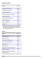
Table of contents
General information on page 3
Maintenance on page 4
Troubleshooting and diagnostics on page 17
Replacement parts and accessories on page 23
General information
In no event will the manufacturer be liable for direct, indirect, special,
incidental or consequential damages resulting from any defect or
omission in this manual. The manufacturer reserves the right to make
changes in this manual and the products it describes at any time, without
notice or obligation. Revised editions are found on the manufacturer’s
website.
Safety information
N O T I C E
The manufacturer is not responsible for any damages due to misapplication or
misuse of this product including, without limitation, direct, incidental and
consequential damages, and disclaims such damages to the full extent permitted
under applicable law. The user is solely responsible to identify critical application
risks and install appropriate mechanisms to protect processes during a possible
equipment malfunction.
Please read this entire manual before unpacking, setting up or operating
this equipment. Pay attention to all danger and caution statements.
Failure to do so could result in serious injury to the operator or damage
to the equipment.
Make sure that the protection provided by this equipment is not impaired.
Do not use or install this equipment in any manner other than that
specified in this manual.
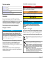
Use of hazard information
D A N G E R
Indicates a potentially or imminently hazardous situation which, if not avoided, will
result in death or serious injury.
W A R N I N G
Indicates a potentially or imminently hazardous situation which, if not avoided,
could result in death or serious injury.
C A U T I O N
Indicates a potentially hazardous situation that may result in minor or moderate
injury.
N O T I C E
Indicates a situation which, if not avoided, may cause damage to the instrument.
Information that requires special emphasis.
Precautionary labels
Read all labels and tags attached to the instrument. Personal injury or
damage to the instrument could occur if not observed. A symbol on the
instrument is referenced in the manual with a precautionary statement.
This symbol, if noted on the instrument, references the instruction
manual for operation and/or safety information.
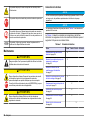
Electrical equipment marked with this symbol may not be disposed of
in European public disposal systems after 12 August of 2005. In
conformity with European local and national regulations (EU Directive
2002/96/EC), European electrical equipment users must now return
old or end-of-life equipment to the Producer for disposal at no charge
to the user.
Note: For return for recycling, please contact the equipment producer or supplier
for instructions on how to return end-of-life equipment, producer-supplied
electrical accessories, and all auxiliary items for proper disposal.
This symbol indicates that a risk of electrical shock and/or
electrocution exists.
English 3

This symbol indicates the need for protective eye wear.
This symbol indicates that the marked item requires a protective earth
connection. If the instrument is not supplied with a ground plug on a
cord, make the protective earth connection to the protective
conductor terminal.
This symbol, when noted on the product, identifies the location of a
fuse or current limiting device.
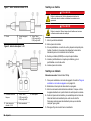
Maintenance
C A U T I O N
Multiple hazards. Only qualified personnel must conduct the tasks
described in this section of the document.
C A U T I O N
Chemical exposure hazard. Obey laboratory safety procedures and
wear all of the personal protective equipment appropriate to the
chemicals that are handled. Refer to the current safety data sheets
(MSDS/SDS) for safety protocols.
C A U T I O N
Chemical exposure hazard. Dispose of chemicals and wastes in
accordance with local, regional and national regulations.
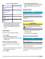
Maintenance schedule
N O T I C E
Failure to complete the 3-month scheduled maintenance tasks on time will result
in operational problems and pump leaks.
N O T I C E
Maintenance tasks that are not shown in Table 1 must only be done by
authorized service personnel.
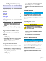
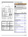
Table 1 shows the recommended schedule of maintenance tasks.
Facility requirements and operating conditions may increase the
frequency of some tasks.
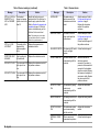
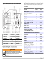
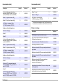
Table 1 Maintenance schedule
Task 1 month 3 months 6 months As necessary
Replace the reagents and
standards on page 5
1
X
Examine the pump, valve
and mixer modules
on page 6
X
Examine the sample
conditioning block filter
on page 6
2
X
Examine the backpressure at
the drain block on page 7
X
Replace the pump piston
seals on page 7
X
Lubricate the pump module
on page 9
X
Replace the valve rotor
on page 10
X
Examine the tubing and
fittings on page 12
X
Clean the mixing chamber
on page 12
X
Replace the sample
conditioning block filter
on page 13
X
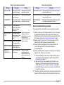
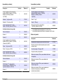
Replace a tube on page 14 X
4 English

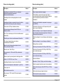
Table 1 Maintenance schedule (continued)
Task 1 month 3 months 6 months As necessary
Replace a fuse on page 15 X
Replace a module
on page 16
X
1
In typical municipal wastewater applications, fill the cleaning solution bottle
every 2 weeks.
2
In typical municipal wastewater applications, inspect the sample conditioning
block filter every 2 weeks.
Put the analyzer in shutdown mode
Stop the analyzer before maintenance tasks are started.
1. Push MENU.
2. Select SENSOR MENU>APA6000 #1 APA 6000>SENSOR
STATUS>STANDBY.
Put the analyzer back into operation
After maintenance tasks are complete, start the analyzer.
1. Make sure that all the tubing is connected and that the front door and
analyzer bottle enclosures are closed and latched.
2. Push MENU.
3. Select SENSOR MENU>APA6000 #1 APA 6000>SENSOR
STATUS>RESTART. The analyzer starts normal operation.
Clean the instrument
N O T I C E
Never use cleaning agents such as turpentine, acetone or similar products to
clean the instrument including the display and accessories.
Clean the exterior of the instrument with a moist cloth and a mild soap
solution.
How to clean spills
C A U T I O N
Chemical exposure hazard. Dispose of chemicals and wastes in
accordance with local, regional and national regulations.
1. Obey all facility safety protocols for spill control.
2. Discard the waste according to applicable regulations.
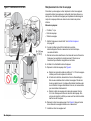
Replace the reagents and standards
N O T I C E
Do not operate the analyzer when the analyzer bottles are not installed. Dry
operation may damage the analyzer.
Replace the reagents and standards before the level in an analyzer
bottle is less than 10%. Measurements are not accurate when the level
is less than 10%.
The manufacturer recommends that all the reagents and standard
solution bottles be replaced at the same time. Do not mix old and new
reagents.
1. Put the analyzer in shutdown mode. Refer to Put the analyzer in
shutdown mode on page 5.
2. Open the analyzer bottle enclosures. Put a paper towel on the
bottom of each enclosure lid.
3. Remove the cap and tubes from all the analyzer bottles. Put them on
the paper towel to absorb any drips or leakage.
4. Remove the analyzer bottles from the enclosures.
5. Make sure that the analyzer bottle enclosure and tubing in the
enclosure is clean. Refer to How to clean spills on page 5.
6. For the high range hardness analyzer, prepare Reagent 2. Refer to
Prepare Reagent 2 (HR hardness analyzer only) on page 6.
7. Make sure the cleaning solution bottle is full. Add cleaning solution
as necessary.
8. Install the new analyzer bottles in the bottle enclosures.
English
5

9. Remove the bottle cap and protective seal from the analyzer bottles.
10. Make sure that 12.7 mm (0.5-in.) of the tubing comes out of the
bottom of each straw.
11. Install the correct analyzer bottle cap and tube assembly on each
bottle. Each tube has a label that identifies the corresponding bottle.
12. Close the bottle enclosures. Discard the used paper towels.
13. Prime the analyzer and set the bottle levels to 100%. Refer to Prime
the analyzer on page 6.
14. When the priming is complete, start the analyzer. Refer to Put the
analyzer back into operation on page 5. The analyzer will
automatically start sample measurement.
15. Let the analyzer readings stabilize (3–6 hours), then calibrate the
analyzer. Push MENU and select SENSOR
MENU>APA6000 #1 APA 6000>CALIBRATION>EXECUTE
CALIBRATION to start a calibration.
Prepare Reagent 2 (HR hardness analyzer only)
Reagent 2 is supplied as a liquid and a powder that must be mixed
together before use. The approximate shelf life of the prepared reagent
is 3 months.
1. Remove the cap and seal from the Reagent 2 bottle. The seal can be
discarded.
2. Put the supplied powder funnel in the Reagent 2 bottle.
3. Add the powder to the liquid.
4. Install the original cap.
5. Hold the cap tight to prevent loosening and shake the bottle until the
powder is dissolved.
Prime the analyzer
Make sure to plumb the sample lines and drain hoses and install the
reagent and standard bottles before this task is started.
1. Push MENU and select SENSOR MENU>APA6000 #1 APA
6000>SOLUTIONS AND CLEANING>PRIMING>PRIME ENTIRE
SYSTEM NOW to prime the analyzer.
Priming takes 7–15 minutes. A pop-up window shows the time that
remains to complete the prime cycle. When the priming is complete,
the analyzer automatically starts sample measurement.
2. If bubbles are seen in the tubing after the analyzer is primed, do step
1 again to remove the bubbles (maximum of 4 times).
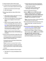
Examine the pump, valve and mixer modules
1. Examine the front of the pump, valve and mixer modules and tubing
for leaks. Tighten or replace fittings as necessary to stop leaks. Refer
to Replace a tube on page 14 to tighten or replace fittings or
replace tubing.
2. Open the module panel.
3. Examine for leaks on the back side of the pump, valve and mixer
modules. Tighten or replace fittings as necessary to stop leaks. Refer
to Replace a tube on page 14 to tighten or replace fittings or
replace tubing.
4. Examine for contamination buildup in the tubing. If contamination
buildup is seen, start a cleaning cycle.
a. Push MENU.
b. Select SENSOR MENU>APA6000 #1 APA 6000>SOLUTIONS
AND CLEANING>INSTRUMENT CLEAN>CLEAN SYSTEM
NOW.
Examine the sample conditioning block filter
N O T I C E
If the sample condition block filter is removed from the instrument, make sure to
replace it with an alternative filtration system of 0.5 µm or smaller. Failure to
supply the required filtration will void the instrument warranty.
Unfiltered sample flows around the outside of the filter to continuously
self-clean the filter. Increase the sample flow to the sample conditioning
block as necessary to improve self-cleaning. Set the flow rate to
100–2000 mL/minute (500–1000 mL/minute is recommended).
6
English

1. Make sure that the sample inlet tubing does not have a blockage. If it
does, replace the tubing. Refer to Replace a tube on page 14.
2. Make sure that the 0.5 µm filter in the sample conditioning block
does not have a blockage. If it does, replace the filter. Refer to
Replace the sample conditioning block filter on page 13. Do not
clean and reuse the filter.
Examine the backpressure at the drain block
1. Make sure that the maximum pressure reading on the pressure
gauge at the drain block is about 1.4–1.7 bar (20–25 psi). Maximum
pressure occurs when the pump module pushes fluid through the
detector line.
a. If the maximum pressure is less than 1.4–1.7 bar (20–25 psi), the
pump piston seals may have a leak. Replace the pump piston
seals. Refer to Replace the pump piston seals on page 7.
b. If the maximum pressure is more than 1.4–1.7 bar (20–25 psi),
the backpressure device has contamination buildup. Replace the
backpressure device as necessary.
2. Make sure that the minimum pressure reading on the pressure
gauge at the drain block is about 0.35–0.7 bar (5–10 psi) less than
the maximum.
If the pressure gauge reads 2 bar (20 psi) while the pump module is
operating, then decreases to below 0.35 bar (5 psi) after the pump
stops, the rotary valve may have a leak. Examine the rotary valve
and tubing for leaks.
Replace the pump piston seals
N O T I C E
Failure to replace the pump piston seals every 3 months will void the warranty.
Replace the pump piston seals to prevent pump leakage. Pump leakage
can cause the pump piston to get stuck, corrosion of internal parts and
the piston guide to get stuck in the motor housing.
Items to collect:
• Wrench, open-end, ¾-in.
• Pump piston seals (2x)
• O-ring, fluorocarbon, 0.676-in. ID x 0.070-in. wide
• Alignment tool for the pump module
1. Put the analyzer in shutdown mode. Refer to Put the analyzer in
shutdown mode on page 5.
2. Set the power switch to off. The piston will be fully forward.
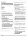
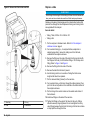
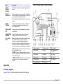
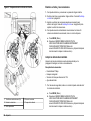
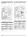
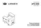
3. Remove the pump body assembly from the pump module. Refer to
the illustrated steps in Figure 1.
a. Remove the two tubes connected to the pump body assembly.
b. Remove the knurled lock ring from the pump body assembly.
Keep for later use.
c. Gently pull the pump body assembly away from the pump module
base and off the piston. Make sure not to bend the piston and
lead screw assembly.
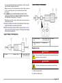
4. Use a ¾-in. open-end wrench to loosen the ceramic piston guide
from the pump body assembly. Turn the piston guide to remove it.
Keep for later use. Refer to Figure 2.
5. Replace the piston seals. Refer to Figure 2.
a. Remove the two piston seals from the seal retaining ring and
discard. Make sure not to damage the seal retaining ring.
b. Install two new piston seals on the seal retaining ring. Put one
seal flanged-side up and push the seal retaining ring on it. Do the
same for the opposite side. Make sure that both rings are fully
seated and that the exposed edge is flat.
6. If leakage has occurred, replace the O-ring. Refer to Figure 2.
a. Remove the O-ring seated in the assembly. Do not use a sharp
tool to remove the O-ring or pump body damage could occur.
b. Install a new O-ring. Make sure that the O-ring is fully seated in
the groove.
7. Assemble the pump body assembly.
a. Lower the assembled part into the pump body so that it sits on
the O-ring. Refer to Figure 2.
English
7

b. Install the ceramic piston guide and tighten until resistance is felt,
then loosen ½ turn so the seal retaining ring can move freely.
c. Fully insert the stainless steel alignment tool.
d. Securely hand-tighten the piston guide into the pump body.
e. Use a wrench to tighten the piston guide to 4.5–9 Nm (40–60 in.-
lb).
f. Pull the alignment tool out of the assembled pump body.
8. Install the pump body assembly on the pump module. Do the
illustrated steps shown in Figure 1 in reverse order.
a. Push the assembled unit on the pump piston with the weep hole
at the bottom.
b. Install the knurled lock ring and hand-tighten it. Make sure that
there is no movement of the pump body after the lock ring is
tightened.
c. Install the two tubes to the pump body assembly.
9. Set the power switch to on.
10. Push MENU and select SENSOR MENU>APA6000 #1 APA
6000>SOLUTIONS AND CLEANING>PRIMING>PRIME ENTIRE
SYSTEM NOW. Priming takes 7–15 minutes.
Note: When priming starts, a pop-up window shows the time that remains to
complete the prime cycle. When the priming is complete, the analyzer
automatically starts sample measurement.
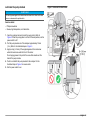
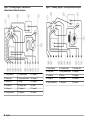
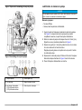
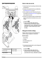
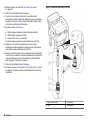
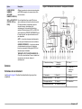
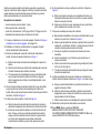
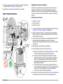
Figure 1 Remove the pump body assembly
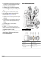
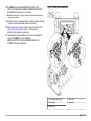
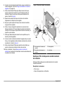
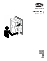
Figure 2 Pump body assembly
1 Pump body 4 Piston seal (2x)
2 Weep hole 5 Seal retaining ring
3 O-ring, fluorocarbon, 0.676-in. ID x
0.070-in. OD
6 Piston guide, ceramic
8 English

Lubricate the pump module
N O T I C E
Too much grease applied to the lead screw can cause dirt to collect on the lead
screw or contaminate the optical switch.
Items to collect:
• Phillips screwdriver
• Grease, high temperature, non-flammable
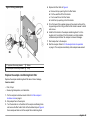
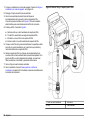
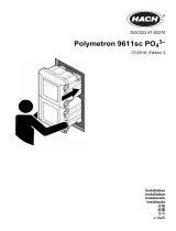
1. Open the analyzer door and look at the pump piston. Refer to
Figure 3. When the pump piston is in the full forward position, set the
power switch to off.
2. Pull the pump module out of the analyzer approximately 76 mm
(3 in.). Refer to the illustrated steps in Figure 3.
3. Apply a drop (2–3 mm) of the supplied grease to the lead screw
where the lead screw exits the front of the motor.
Do not apply grease to the part of the screw that extends out the
back of the pump module.
4. Push in and attach the pump module to the analyzer. Do the
illustrated steps in Figure 3 in reverse order.
5. Set the power switch to on.
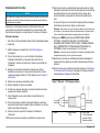
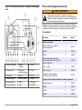
Figure 3 Lubricate the lead screw
English 9

Replace the valve rotor
To prevent valve leakage, replace the valve rotor and inspect the valve
stator for wear or scratches. Valve leakage can quickly cause damage to
the rotary valve body due to corrosion of internal parts.
Items to collect:
• Allen wrench,
7
/
64
-in.
• Valve rotor
• Valve stator
1. Put the analyzer in shutdown mode. Refer to Put the analyzer in
shutdown mode on page 5.
2. Open the reagent enclosure and standard/cleaning solution
enclosure. Put a paper towel on the bottom of each enclosure lid.
3. Remove the bottle caps and tube assemblies from all the analyzer
bottles to prevent siphoning. Put them on the paper towel to absorb
any drips or leakage.
4. Stop sample flow to the analyzer.
5. Remove the valve stator. Refer to Figure 4.
a. Remove the tube fittings from ports 4, 7 and 10 of the rotary valve
to get clearance for the allen wrench.
b. Use the allen wrench to loosen the three recessed socket head
cap screws in the valve stator. Be careful not to lose the screws
or the spacer ring that the screws hold in position. Remove the
spacer ring and screws and keep for later use.
c. Pull the valve stator away from the valve module. About 2–3 mL
of fluid may drain from the valve stator. If the volume is large,
make sure that the tubes where removed from the analyzer
bottles.
6. Remove the used valve rotor. Refer to Figure 4. Dry all surfaces of
the rotary valve with a paper towel.
7. Install a new valve rotor.
8. Dry and inspect the surfaces of the valve stator.
9. If the rear surface of the valve stator has circular grooves or excess
wear, replace the valve stator.
a. Remove all the tube fittings from the valve stator.
b. Discard the valve stator.
10. With the spacer ring in position, install the valve stator.
a. Position the valve stator with port 1 at the 12 o’clock (top center)
position on the valve body.
b. Make sure that the locating pins in the valve body align with the
locating pin holes on the back side of the valve stator.
c. Hold the valve stator in position. Install and turn the socket head
cap screws to tighten. Refer to Figure 4. Tighten in even
increments until the valve rotor and valve spacer are seated on
the valve body (100 to 120 inch-ounces of torque or 0,7 to
1,4 Joules of torque). Do not over-tighten or valve damage will
occur.
Note: An even resistance is felt as the socket head cap screws are
tightened because an internal spring washer is being compressed.
11. Install the removed tube fittings in the rotary valve. Fittings should be
securely finger tightened. Do not over-tighten the fittings because
that will pinch the tubing at the ferrule and slow or stop liquid flow
through the tube.
If a fitting has been over-tightened, cut off the pinched end of the
tube and use a new ferrule.
Note: In some cases, a tool may be necessary to tighten a fitting a maximum
of ¼ turn. If leakage continues, the valve stator or valve fitting may require
cleaning or replacement. Loose fittings result in air or liquid leaks and poor
analyzer performance.
12. Install the bottle caps and tube assemblies in the analyzer bottles.
a. Make sure that 12.7 mm (0.5-in.) of the tubing comes out of the
bottom of each straw.
b. Install the correct bottle cap and tube assembly on each analyzer
bottle. Each tube has a label that identifies the corresponding
analyzer bottle.
c. Close the reagent enclosure and standard/cleaning solution
enclosure. Discard the used paper towels.
13. Start sample flow to the analyzer.
10
English

14. Push MENU and select SENSOR MENU>APA6000 #1 APA
6000>SOLUTIONS AND CLEANING>PRIMING>PRIME ENTIRE
SYSTEM NOW. Priming takes 7–15 minutes.
Note: When priming starts, a pop-up window shows the time that remains to
complete the prime cycle.
15. If bubbles are seen in the tubing after the analyzer is primed, do step
14 again to remove the bubbles (maximum of 4 times).
16. When the priming is complete, start the analyzer. Refer to Put the
analyzer back into operation on page 5. The analyzer will
automatically start sample measurement.
17. Let the analyzer readings stabilize (3–6 hours), then calibrate the
analyzer. Push MENU and select SENSOR
MENU>APA6000 #1 APA 6000>CALIBRATION>EXECUTE
CALIBRATION to start a calibration.
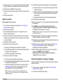
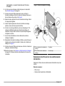
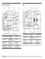
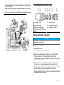
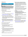
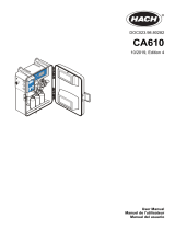
Figure 4 Rotary valve components
1 Socket head cap screws (3x) 4 Valve rotor
2 Valve stator 5 Valve body
3 Spacer ring
English 11

Examine the tubing and fittings
1. Examine all the tubing and fittings for leaks and/or damage.
2. Replace tubes with leaks or damage. Refer to Replace a tube
on page 14.
3. Tighten or replace fittings as necessary to stop leaks. Refer to
Replace a tube on page 14 to tighten or replace fittings.
4. Examine for contamination buildup in the tubing. If contamination
buildup is seen, start a cleaning cycle.
a. Push MENU.
b. Select SENSOR MENU>APA6000 #1 APA 6000>SOLUTIONS
AND CLEANING>INSTRUMENT CLEAN>CLEAN SYSTEM
NOW.
Clean the mixing chamber
Clean the mixing chamber when it becomes discolored by biogrowth,
staining or sediment.
Items to collect:
• Phillips screwdriver
• Cotton swabs
• 10% household bleach solution
• Deionized water
1. For safety reasons, do a cleaning cycle before the mixing chamber is
opened.
a. Push MENU.
b. Select SENSOR MENU>APA6000 #1 APA 6000>SOLUTIONS
AND CLEANING>INSTRUMENT CLEAN>CLEAN SYSTEM
NOW.
2. When the cleaning cycle is complete, put the analyzer in shutdown
mode. Refer to Put the analyzer in shutdown mode on page 5.
3. Use the Phillips screwdriver to loosen the two screws that attach the
mixing chamber to the front of the mixing module. Note that the block
is divided into two pieces. Refer to Figure 5.
4. Separate the two pieces of the mixing chamber block. Make sure not
to lose the stir bar.
5. Let the top part of the mixing chamber block hang from the attached
tubing.
6. Use a cotton swab soaked with a 10% household bleach solution to
clean the mixing chamber parts. If necessary, also clean the surface
that the stir bar sits on and the stir bar.
7. Use deionized water to fully rinse the cleaned surfaces and stir bar.
8. Reassemble the mixing chamber. Make sure that the O-ring and stir
bar are correctly installed in the mixing chamber. Refer to Figure 5.
9. Use the Phillips screwdriver to tighten the two screws that attach the
mixing chamber to the mixing module.
10. Start the analyzer. Refer to Put the analyzer back into operation
on page 5. The analyzer automatically starts sample measurement.
12 English

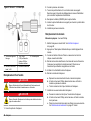
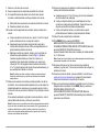
Figure 5 Mixing module parts
1 Top piece of the mixing chamber 3 Stir bar
2 Bottom piece of the mixing chamber 4 O-ring
Replace the sample conditioning block filter
Replace the sample conditioning block filter when it has a blockage.
Items to collect:
• Filter, 0.5 µm
• Grease, high temperature, non-flammable
1. Put the analyzer in shutdown mode. Refer to Put the analyzer in
shutdown mode on page 5.
2. Stop sample flow to the analyzer.
3. Turn the knurled nut on the bottom of the sample conditioning block
and remove the filter holder. Refer to the illustrated steps in Figure 6.
Some sample will drain out of the sample filter conditioning block.
4. Replace the filter. Refer to Figure 6.
a. Remove the top quad ring from the filter holder.
b. Pull the used filter off the filter holder.
c. Push a new filter on the filter holder.
d. Install the top quad ring on the filter holder.
5. Put a thin bead of the supplied grease on the exterior surface of the
top quad ring and the O-ring so that the filter holder is easier to install
and remove.
6. Install the filter holder in the sample conditioning block. Turn the
knurled nut to fully tighten. If the filter holder is not fully installed,
unfiltered sample will enter the analyzer and cause blockages.
7. Start sample flow to the analyzer.
8. Start the analyzer. Refer to Put the analyzer back into operation
on page 5. The analyzer automatically starts sample measurement.
English 13

Figure 6 Remove the filter holder and filter
1 Quad ring 3 O-ring
2 Filter 4 Knurled nut
Replace a tube
N O T I C E
Do not change the tube lengths of the holding coil tubes or the tube between the
rotary valve and mixer chamber because this will affect analyzer performance.
Replace a tube when it has damage and/or contamination buildup that
prevents flow through the tube. Replacement tubing and a tubing cutter
are supplied with the analyzer.
Items to collect:
• Tubing, Tefzel, 0.030-in. ID x 0.062-in. OD
• Tubing cutter
1. Put the analyzer in shutdown mode. Refer to Put the analyzer in
shutdown mode on page 5.
2. For an external tubing (i.e., to analyzer bottles, sample inlet or
sample bypass drain), remove the tubing cover from the back,
underside of the analyzer enclosure.
3. Remove the fittings on the ends of the tube from their ports. Identify
the fittings on the tube (¼-28 flat bottom fitting or 10-32 rotary valve
fitting). Refer to Figure 7 and Figure 8.
4. Remove the fittings from the ends of the tube.
5. Remove the label from the tube if present.
6. Use the tubing cutter to cut a section of tubing that is the same
length as the tube to be replaced.
7. Put the removed label (if present) on the new tube.
8. For an external tube, put the tube through the rubber grommet, then
put it into the correct position in the manifold on the interior bottom of
the analyzer enclosure.
9. Put the tubing in the correct location on the exterior and interior of
the instrument.
10. Install new fittings on the ends of the new tube.
11. Tighten the fittings on the ends of the tube into the ports. Fittings
should be securely finger tightened. Do not over-tighten the rotary
valve fittings because that will pinch the tubing at the ferrule and slow
or stop liquid flow through the tube.
14
English

If a rotary valve fitting has been over-tightened, cut off the pinched
end of the tube and use a new ferrule.
Note: In some cases, a tool may be necessary to tighten a fitting a maximum
of ¼ turn. Loose fittings result in air or liquid leaks and poor analyzer
performance.
12. Push MENU and select SENSOR MENU>APA6000 #1 APA
6000>SOLUTIONS AND CLEANING>PRIMING>PRIME ENTIRE
SYSTEM NOW. Priming takes 7–15 minutes.
Note: When priming starts, a pop-up window shows the time that remains to
complete the prime cycle.
13. Examine the fittings on the ends of the replacement tube for leaks.
Tighten the fittings as necessary to stop leaks.
14. When the priming is complete, start the analyzer. Refer to Put the
analyzer back into operation on page 5. The analyzer automatically
starts sample measurement.
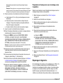
Figure 7 Fitting – 10-32 rotary valve
1 Ferrule 2 Hex nut, 10-32 3 Tubing, Tefzel, 0.030-
in. ID x 0.062-in. OD
Figure 8 Fitting – ¼-28 flat bottom
1 Ferrule with locking
ring
3 Tubing, Tefzel, 0.030-
in. ID x 0.062-in. OD
5 Flat end
2 Fitting, flangeless nut,
¼–28
4 Chamfered end
Replace a fuse
D A N G E R
Electrocution hazard. Remove power from the instrument before doing
maintenance or service activities.
D A N G E R
Fire hazard. Use the same type and current rating to replace fuses.
1. Open the analyzer door.
2. Open the module panel.
English
15

3. Turn the fuse carrier ¼ turn and pull it out of the fuse holder. Refer to
Wiring connections in the installation manual for the fuse locations.
4. Replace the fuse (5208300) in the fuse carrier.
5. Push the fuse carrier in the fuse holder and then turn the fuse carrier
¼ turn.
6. Install the module panel.
Replace a module
Item to collect: Phillips screwdriver
1. Put the analyzer in shutdown mode. Refer to Put the analyzer in
shutdown mode on page 5.
2. Set the power switch to off.
3. Open the analyzer bottle enclosures. Put a paper towel on the
bottom of each enclosure lid.
4. Remove the bottle caps and tube assemblies from all the analyzer
bottles to prevent siphoning. Put them on the paper towel to absorb
any drips or leakage.
5. Stop sample flow to the analyzer.
6. Remove the module from the analyzer.
a. Remove all tube fittings from the module to be replaced.
b. Use the Phillips screwdriver to loosen the two screws that attach
the module to the module panel.
c. Pull the module straight out of the analyzer.
7. Install the new module in the analyzer.
a. Push the new module straight into the analyzer.
b. Use the Phillips screwdriver to tighten the two screws that attach
the module to the module panel.
c. Install the tube fittings in the ports of the new module. Refer to
Plumbing diagrams on page 21. Fittings should be securely
finger tightened. Do not over-tighten the fittings.
Note: In some cases, a tool may be necessary to tighten a fitting a
maximum of ¼ turn. Loose fittings result in air or liquid leaks and poor
analyzer performance.
8. Install the bottle caps and tube assemblies in the analyzer bottles.
a. Make sure that 12.7 mm (0.5-in.) of the tubing comes out of the
bottom of each straw.
b. Install the correct bottle cap and tube assembly on each analyzer
bottle. Each tube has a label that identifies the corresponding
analyzer bottle.
c. Close the bottle enclosures. Discard the used paper towels.
9. Start sample flow to the analyzer.
10. Set the power switch to on. The analyzer automatically starts sample
measurement.
11. Push MENU and select SENSOR MENU>APA6000 #1 APA
6000>SOLUTIONS AND CLEANING>PRIMING>PRIME ENTIRE
SYSTEM NOW. Priming takes 7–15 minutes.
Note: When priming starts, a pop-up window shows the time that remains to
complete the prime cycle.
12. Examine the fittings on the ends of the replacement tube for leaks.
Tighten the fittings as necessary to stop leaks.
13. If bubbles are seen in the tubing after the analyzer is primed, do step
11 again (maximum of 4 times).
14. When the priming is complete, start the analyzer. Refer to Put the
analyzer back into operation on page 5. The analyzer will
automatically start sample measurement.
15. Let the analyzer readings stabilize (3–6 hours), then calibrate the
analyzer. Push MENU and select SENSOR
MENU>APA6000 #1 APA 6000>CALIBRATION>EXECUTE
CALIBRATION to start a calibration.
Prepare the analyzer for storage or shipping
Remove all the fluids and the power from the analyzer before long-term
storage or shipping.
1. Put the analyzer in shutdown mode. Refer to Put the analyzer in
shutdown mode on page 5.
2. Stop the flow of sample to the analyzer.
16
English

3. Remove the analyzer bottles and pour the solutions into an
applicable drain.
4. Flush and fill the analyzer bottles with deionized water.
5. Install the analyzer bottles in the bottle enclosures and complete a
prime cycle two times.
a. Push MENU.
b. Select SENSOR MENU>APA6000 #1 APA 6000>SOLUTIONS
AND CLEANING>PRIMING>PRIME ENTIRE SYSTEM NOW to
start a prime cycle.
6. Remove the analyzer bottles and pour the solutions into an
applicable drain.
7. Set the power switch to off.
8. Clean the bottle enclosures. Refer to How to clean spills on page 5.
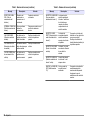
Troubleshooting and diagnostics
When an alarm or warning is active, a number (1–8) or "N" shows at the
bottom of the screen. A number shows when a sensor warning, sensor
alarm or set point alarm is active. The number identifies the analyzer that
has an active alarm/warning. "N" shows when a Aquatrend network
alarm is active. If the flash on alarm setting is enabled, the screen also
flashes.
To see the alarm/warning message, push MENU and select ALARM
LOG>1-APA6000 #1 APA 6000>WARNING/ALARM LOG (or SET
POINT ALARM LOG).
• Warning/Alarm Log—contains the sensor warnings and sensor
alarms that have occurred (maximum of 14). Refer to Table 2 and
Table 3. Sensor warnings identify a condition that requires user
attention, but the condition does not prevent the analyzer from
accurately measuring and displaying sample readings. Sensor alarms
cause the analyzer to go to standby mode because the analyzer is not
able to accurately measure and display sample readings.
• Set Point Alarm Log—contains the set point alarms that have
occurred (maximum of 14). Refer to Table 4. A set point alarm only
occurs when a set point is configured in the alarm settings.
The most recent alarm/warning shows at the top of the list. A bell icon
shows to the left of the alarms/warnings that are active. Select an
alarm/warning and push ENTER to see the alarm details. When the
alarm/warning is selected, the alarm/warning is acknowledged
(deactivated).
When the warning/alarm log or set point alarm log is full, no new alarms
are added to them. Warnings/alarms are not automatically erased to
make space for new warnings/alarms. Make sure to periodically erase
the alarms from the alarm/warning logs.
• To erase the set point alarm log and sensor alarm logs, push MENU
and select SENSOR MENU>APA6000 #1 APA 6000>SENSOR
DIAGNOSTICS>CLEAR ALARM LOG>YES.
• To erase the Network and AquaTrend alarm log, push MENU and
select AQUATREND MENU>AQUATREND DIAGNOSTICS>CLEAR
ALARM LOG>YES.
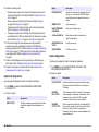
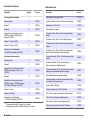
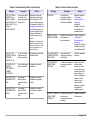
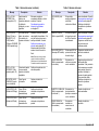
Table 2 Sensor warnings
Message Description Solution
POWER FAILURE The power source
was temporarily
disconnected or set
to off.
None
Note: To disable warnings triggered by
power failures, push MENU and select
SENSOR MENU>APA6000 #1 APA
6000>SENSOR
DIAGNOSTICS>SENSOR WARNING
OPTIONS>OFF.
CAL STD1 (or 2)
REPEATABILITY
The readings of the
calibration standard
vary.
This warning is typically caused by
a mechanical failure. Refer to
General troubleshooting
procedure on page 19.
STD1 (or 2) FAIL
ACC/REP
The readings of the
standard are not
within acceptable
calibration limits and
are not repeatable.
This warning is typically caused by
a mechanical failure. Refer to
General troubleshooting
procedure on page 19.
English 17

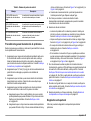
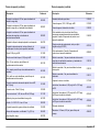
Table 2 Sensor warnings (continued)
Message Description Solution
STD1 (or 2) LOW or
REAGENT1 (or 2)
LOW or CLEANER
LOW
The standard,
reagent or cleaning
solution level is less
than 5%.
Identify the fluid level in each
analyzer bottle. If the fluid level is
almost empty, replace the bottle.
Refer to Replace the reagents and
standards on page 5. If the fluid
level is not almost empty, set the
fluid level to the correct level.
Note: This warning only occurs when
the Level Monitor function is enabled.
Refer to the operations manual.
STD1 (or 2) FAIL
ACCURACY
The reading of the
standard is not
within acceptable
limits.
Replace the reagents and/or
standard solutions.
DETECTOR LIGHT
LEAKAGE
Light is getting into
the colorimeter.
Replace the colorimeter module.
LED OUTPUT LOW The colorimeter LED
light output is too
low.
Replace the colorimeter module if
the problem continues.
LED OUTPUT HIGH The colorimeter LED
light output is too
high.
Replace the colorimeter module if
the problem continues.
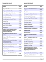
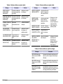
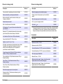
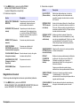
Table 3 Sensor alarms
Message Description Solution
A/D FAILURE The main analog to
digital converter of the
colorimeter module has
failed.
Start the analyzer. Refer to
Put the analyzer back into
operation on page 5.
Replace the colorimeter
module if the problem
continues.
RAM TEST FAILED The RAM on the APA
main circuit board has
malfunctioned.
Start the analyzer. Refer to
Put the analyzer back into
operation on page 5.
Contact technical support if
the problem continues.
INVALID DIP SWITCH The chemistry DIP switch
is set to an illegal
location.
Contact technical support.
VALVE COMM FAIL The valve module is not
communicating with the
controller.
Make sure that all the
cables are securely
connected. If corrosion is
present on the harness that
connects to the backplane,
clean the contacts. Replace
the harness or backplane if
corrosion is visible. Replace
the valve module if the
problem continues.
BURETTE1 COMM
FAIL
The autoburette (pump)
module is not
communicating with the
controller.
Replace the autoburette
module.
MIXER COMM FAIL The mixing module is not
communicating with the
controller.
Replace the mixing module.
DETECTOR COMM
FAIL
The colorimeter module
is not communicating
with the controller.
Replace the colorimeter
module.
INTERNAL COMM
FAIL
There is an internal
communication problem.
Contact technical support.
18 English

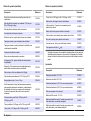
Table 3 Sensor alarms (continued)
Message Description Solution
VALVE NO HOME The valve was not able
to find its home signal.
Replace the valve module if
the problem continues.
VLV HOME SIG ON The home signal of the
valve is always on.
Replace the valve module.
VLV MOVE ERR The valve was not able
to move to the necessary
port.
Replace the valve module if
the problem continues.
BURETTE1 HOME
ERR
The home location for
Burette 1 went outside of
its limit from the last
Home check.
Identify if the tubing has a
blockage or if there is
plumbing that is not correct.
Replace the pump
(autoburette) module if the
problem continues.
BURETTE1 HOME
DRIFT
The cumulative offset
drift from Home is higher
than the acceptable
limits.
BURETTE1 NO HOME Burette1 was not able to
find its home location.
BURETTE1 HOME ON The home signal for
Burette1 is always on.
SAMPLE1 (or
SAMPLE2) OUT
There is no sample flow
to the analyzer.
Identify if the sample
conditioning unit has a
blockage. Make sure that
there is sample flow to the
analyzer.
Table 4 Set point alarms
Message Description
LOW ALARM value units The sample measurement is less than the set point
value selected by the user.
HIGH ALARM value units The sample measurement is more than the set point
value selected by the user.
RATE ALARM value
units
The sample measurement rate change is more than
the set point value selected by the user.
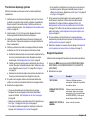
General troubleshooting procedure
Do the steps that follow to identify the cause of operational problems.
1. Make sure that none of the analyzer bottles are empty. If an reagent
or standard solution bottle is empty, replace all the reagent and
standard solution bottles. Make sure that the cleaning solution bottle
is full. Refer to Replace the reagents and standards on page 5.
2. Make sure that 12.7 mm (0.5-in.) of the tubing comes out of the
bottom of each straw that goes in the analyzer bottles.
3. Make sure that the tubing going into the analyzer bottles is the
correct tubing. Each tube has a label that identifies the
corresponding bottle.
4. Make sure that the tubes connected to the rotary valve are filled with
fluid and not air. If there is air in the tubes:
a. Examine the tubing for kinks and/or crushed areas that prevent
flow through the tubing. Replace tubing with damage. Refer to
Replace a tube on page 14.
b. Make sure that flow is not prevented by fittings that are over-
tightened. Cut off the pinched end of the tube and use a new
ferrule. Refer to Figure 7 on page 15 and Figure 8 on page 15.
c. Examine the tubing connections and the seal on the bottle caps
for leaks. Fix any leaks.
5. If the tubing to the rotary valve has been recently been disconnected,
make sure that the tubing is correctly connected to the rotary valve.
English
19

6. Examine the rotary valve.
• Premature wear may occur in the valve. Replace the valve rotor
and examine the stator for scratches. Refer to Replace the valve
rotor on page 10.
• Clean or replace a tube fitting if it has a leak. Refer to Figure 7
on page 15 and Figure 8 on page 15.
• If the valve module body has a leak, replace the valve module.
Refer to Replace a module on page 16.
• If reagents or sample are not flowing, the fittings may have been
over-tightened. Cut off the pinched end of the tube and use a new
ferrule. Refer to Figure 7 on page 15 and Figure 8 on page 15.
7. If air moves through the pump piston seals during operation,
examine the sample conditioning block filter. If the filter has a
blockage, replace the filter. Refer to Replace the sample conditioning
block filter on page 13. If filter does not have a blockage, replace the
pump piston seals. Refer to Replace the pump piston seals
on page 7.
8. If there is fluid leakage around the pump body, replace the pump
piston seals. Refer to Replace the pump piston seals on page 7.
9. Examine the pressure at the drain block. Refer to Examine the
backpressure at the drain block on page 7.
Aquatrend diagnostics
Use the Aquatrend diagnostic tests to troubleshoot problems.
1. Push MENU and select AQUATREND MENU>AQUATREND
DIAGNOSTI CS.
2. Select an option.
Option Description
DISPLAY TEST Identify if the display is operating correctly. Make
sure that the display shows a checkerboard
pattern.
Option Description
KEYBOARD TEST Identify if the keys are operating correctly. Push
any key (i.e., an arrow key or ENTER). Make
sure that the key that is pushed shows on the
display.
MEMORY TEST Start a memory test.
VERIFY PROGRAM
CHECKSUM
Start a verify checksum test.
CLEAR ALARM LOG Erase the alarms from the Network and
AquaTrend alarm log.
AQUATREND COLD
START
For Service use only
SERVICE MENU For Service use only
Sensor diagnostics
Use the sensor diagnostic tests to troubleshoot problems.
1. Push MENU and select SENSOR MENU>APA6000 #1 APA
6000>SENSOR DIAGNOSTICS.
2. Select an option.
Option Description
HOLD OUTPUTS Hold the recorder analog outputs and alarm relays at
their present values/on-off states for a maximum of
30 minutes.
INTERNAL
RELAY TEST
Set the alarm relay (Alarm A or Alarm B) to energized
or de-energized for a maximum of 30 minutes. Use a
continuity meter on the NO and NC relay output
terminals to confirm the relay status selected.
INTERNAL
OUTPUT TEST
Set the recorder output (Recorder A or Recorder B) to
the zero level value (4 mA), half level value (12 mA) or
the full level value (20 mA) for a maximum of
30 minutes. Use this option to confirm operation of the
connected devices.
20 English
La page est en cours de chargement...
La page est en cours de chargement...
La page est en cours de chargement...
La page est en cours de chargement...
La page est en cours de chargement...
La page est en cours de chargement...
La page est en cours de chargement...
La page est en cours de chargement...
La page est en cours de chargement...
La page est en cours de chargement...
La page est en cours de chargement...
La page est en cours de chargement...
La page est en cours de chargement...
La page est en cours de chargement...
La page est en cours de chargement...
La page est en cours de chargement...
La page est en cours de chargement...
La page est en cours de chargement...
La page est en cours de chargement...
La page est en cours de chargement...
La page est en cours de chargement...
La page est en cours de chargement...
La page est en cours de chargement...
La page est en cours de chargement...
La page est en cours de chargement...
La page est en cours de chargement...
La page est en cours de chargement...
La page est en cours de chargement...
La page est en cours de chargement...
La page est en cours de chargement...
La page est en cours de chargement...
La page est en cours de chargement...
La page est en cours de chargement...
La page est en cours de chargement...
La page est en cours de chargement...
La page est en cours de chargement...
La page est en cours de chargement...
La page est en cours de chargement...
La page est en cours de chargement...
La page est en cours de chargement...
La page est en cours de chargement...
La page est en cours de chargement...
La page est en cours de chargement...
La page est en cours de chargement...
La page est en cours de chargement...
La page est en cours de chargement...
La page est en cours de chargement...
La page est en cours de chargement...
La page est en cours de chargement...
La page est en cours de chargement...
La page est en cours de chargement...
La page est en cours de chargement...
La page est en cours de chargement...
La page est en cours de chargement...
La page est en cours de chargement...
La page est en cours de chargement...
La page est en cours de chargement...
La page est en cours de chargement...
La page est en cours de chargement...
La page est en cours de chargement...
-
 1
1
-
 2
2
-
 3
3
-
 4
4
-
 5
5
-
 6
6
-
 7
7
-
 8
8
-
 9
9
-
 10
10
-
 11
11
-
 12
12
-
 13
13
-
 14
14
-
 15
15
-
 16
16
-
 17
17
-
 18
18
-
 19
19
-
 20
20
-
 21
21
-
 22
22
-
 23
23
-
 24
24
-
 25
25
-
 26
26
-
 27
27
-
 28
28
-
 29
29
-
 30
30
-
 31
31
-
 32
32
-
 33
33
-
 34
34
-
 35
35
-
 36
36
-
 37
37
-
 38
38
-
 39
39
-
 40
40
-
 41
41
-
 42
42
-
 43
43
-
 44
44
-
 45
45
-
 46
46
-
 47
47
-
 48
48
-
 49
49
-
 50
50
-
 51
51
-
 52
52
-
 53
53
-
 54
54
-
 55
55
-
 56
56
-
 57
57
-
 58
58
-
 59
59
-
 60
60
-
 61
61
-
 62
62
-
 63
63
-
 64
64
-
 65
65
-
 66
66
-
 67
67
-
 68
68
-
 69
69
-
 70
70
-
 71
71
-
 72
72
-
 73
73
-
 74
74
-
 75
75
-
 76
76
-
 77
77
-
 78
78
-
 79
79
-
 80
80


Hach APA 6000 Manuel utilisateur
- Taper
- Manuel utilisateur
- Ce manuel convient également à
dans d''autres langues
- English: Hach APA 6000 User manual
- español: Hach APA 6000 Manual de usuario
Documents connexes
-
 Hach Lange APA 6000 Maintenance And Troubleshooting Manual
-
 Hach 5500sc Maintenance And Troubleshooting Manual
-
 Hach 5500sc SiO2 Guide d'installation
-
Hach SP-510 Basic User Manual
-
 Hach Polymetron 9611sc Guide d'installation
-
Hach CL17sc Manuel utilisateur
-
-
 Hach CA610 Manuel utilisateur
-
 Hach 5500sc Maintenance And Troubleshooting Manual
-
 Hach Polymetron 9611sc PO43-LR Mode d'emploi


Autres documents
-
BenQ SW2700PT Mode d'emploi
-
STIHL ADG 2 Manuel utilisateur
-
YSI 910 COD Colorimeter Manuel utilisateur
-
Roche cobas e 801 Guide de référence
-
Roche cobas 8000 Data Manager Guide de référence
-
Lamotte 3587 Manuel utilisateur
-
3M Microbial Luminescence System MLSII, 1 ea Mode d'emploi
-
Gima 24618 Le manuel du propriétaire