DOC023.98.80282
CA610
10/2019, Edition 4
User Manual
Manuel de l'utilisateur
Manual del usuario

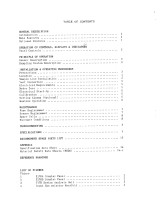
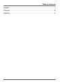
Table of Contents
English..............................................................................................................................3
Français......................................................................................................................... 32
Español.......................................................................................................................... 61
2

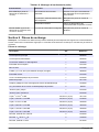
Table of Contents
1 Specifications on page 3
2 General information on page 4
3 Installation on page 7
4 User interface and navigation on page 16
5 Startup on page 17
6 Operation on page 18
7 Maintenance on page 20
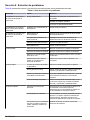
8 Troubleshooting on page 27
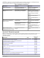
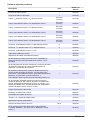
9 Replacement parts on page 30
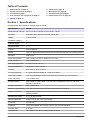
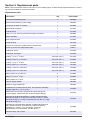
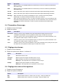
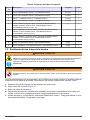
Section 1 Specifications
Specifications are subject to change without notice.
Specification Details
Dimensions (W x H x D) 34.11 x 47.50 x 17.93 cm (13.43 x 18.70 x 7.06 in.)
Enclosure IP62 rating when the door is latched (indoor use)
Weight 11.3 kg (25 lb)
Installation category II
Pollution degree 2
Protection class I
Altitude 2000 m (6560 ft)
Display LCD, 3.5-digit measurement readout and six-character alphanumeric scrolling text line
Mounting Wall mount
Power requirements 100–115/230 VAC; 90 VA, 50/60 Hz; 2.5 A fuse
Power connection 12 to 18 AWG wire
Operating temperature 5 to 40 °C (41 to 104 °F)
Storage temperature –40 to 60 °C (–40 to 140 °F)
Humidity 90% at 40 °C (90% at 104 °F)
Air purge (optional) 0.1 CFM instrument-quality air, ¼-inch O.D. tubing
Alarm relay outputs Two unpowered SPDT relays, each rated at 5 A resistive, 240 VAC maximum.
Alarm connection 12 to 18 AWG wire
Recorder output One isolated recorder output, 4–20 mA (can be adjusted to 0–20 mA), maximum
impedance 500 ohms
Recorder connection 12 to 18 AWG wire
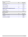
Maximum reagent usage 0.5 L per month (for each of the two standards and one reagent)
Reagent containers High-density polyethylene 0.5 L bottles contained inside the analyzer enclosure and
vented externally.
Measurement range 0.1 to 10 mg/L fluoride
Accuracy/precision ±10% or ±0.10 ppm; ±7% or ±0.07 ppm
Cycle limit 4.2 minutes
Calibration Two-point log/linear with 0.5 mg/L and 5.0 mg/L fluoride standards
Detection limit 0.10 ppm
Certifications CE. Listed to UL and CSA safety standards by ETL.
English 3

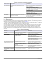
Sample specification
Specification Details
Sample flow rate to sample conditioning 200 to 500 mL/min
Inlet pressure to instrument 1 to 10 psig
Temperature range for sample 5 to 40 °C (41 to 104 °F)
Inlet fitting ¼-inch OD polyethylene tubing with quick-disconnect fitting
Drain fitting ½-inch hose barb
Application sample Drinking/clean water
Section 2 General information
In no event will the manufacturer be liable for direct, indirect, special, incidental or consequential
damages resulting from any defect or omission in this manual. The manufacturer reserves the right to
make changes in this manual and the products it describes at any time, without notice or obligation.
Revised editions are found on the manufacturer’s website.
2.1 Safety information
N O T I C E
The manufacturer is not responsible for any damages due to misapplication or misuse of this product including,
without limitation, direct, incidental and consequential damages, and disclaims such damages to the full extent
permitted under applicable law. The user is solely responsible to identify critical application risks and install
appropriate mechanisms to protect processes during a possible equipment malfunction.
Please read this entire manual before unpacking, setting up or operating this equipment. Pay
attention to all danger and caution statements. Failure to do so could result in serious injury to the
operator or damage to the equipment.
Make sure that the protection provided by this equipment is not impaired. Do not use or install this
equipment in any manner other than that specified in this manual.
2.2 Use of hazard information
D A N G E R
Indicates a potentially or imminently hazardous situation which, if not avoided, will result in death or serious injury.
W A R N I N G
Indicates a potentially or imminently hazardous situation which, if not avoided, could result in death or serious
injury.
C A U T I O N
Indicates a potentially hazardous situation that may result in minor or moderate injury.
N O T I C E
Indicates a situation which, if not avoided, may cause damage to the instrument. Information that requires special
emphasis.
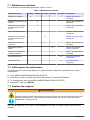
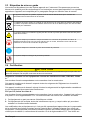
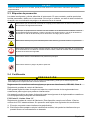
2.3 Precautionary labels
Read all labels and tags attached to the instrument. Personal injury or damage to the instrument
could occur if not observed. A symbol, if noted on the instrument, will be included with a danger or
caution statement in the manual.
4
English

This symbol, if noted on the instrument, references the instruction manual for operation and/or safety
information.
Electrical equipment marked with this symbol may not be disposed of in European domestic or public
disposal systems. Return old or end-of-life equipment to the manufacturer for disposal at no charge to
the user.
This symbol indicates that the marked item can be hot and should not be touched without care.
This symbol indicates that the marked item requires a protective earth connection. If the instrument is
not supplied with a ground plug on a cord, make the protective earth connection to the protective
conductor terminal.
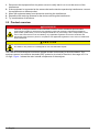
This symbol indicates the need for protective eye wear.
This symbol indicates a potential pinch hazard.
2.4 Certification
C A U T I O N
This equipment is not intended for use in residential environments and may not provide adequate protection to
radio reception in such environments.
Canadian Radio Interference-Causing Equipment Regulation, ICES-003, Class A:
Supporting test records reside with the manufacturer.
This Class A digital apparatus meets all requirements of the Canadian Interference-Causing
Equipment Regulations.
Cet appareil numérique de classe A répond à toutes les exigences de la réglementation canadienne
sur les équipements provoquant des interférences.
FCC Part 15, Class "A" Limits
Supporting test records reside with the manufacturer. The device complies with Part 15 of the FCC
Rules. Operation is subject to the following conditions:
1. The equipment may not cause harmful interference.
2. The equipment must accept any interference received, including interference that may cause
undesired operation.
Changes or modifications to this equipment not expressly approved by the party responsible for
compliance could void the user's authority to operate the equipment. This equipment has been tested
and found to comply with the limits for a Class A digital device, pursuant to Part 15 of the FCC rules.
These limits are designed to provide reasonable protection against harmful interference when the
equipment is operated in a commercial environment. This equipment generates, uses and can
radiate radio frequency energy and, if not installed and used in accordance with the instruction
manual, may cause harmful interference to radio communications. Operation of this equipment in a
residential area is likely to cause harmful interference, in which case the user will be required to
correct the interference at their expense. The following techniques can be used to reduce
interference problems:
English
5

1. Disconnect the equipment from its power source to verify that it is or is not the source of the
interference.
2. If the equipment is connected to the same outlet as the device experiencing interference, connect
the equipment to a different outlet.
3. Move the equipment away from the device receiving the interference.
4. Reposition the receiving antenna for the device receiving the interference.
5. Try combinations of the above.
2.5 Product overview
D A N G E R
Chemical or biological hazards. If this instrument is used to monitor a treatment process and/or
chemical feed system for which there are regulatory limits and monitoring requirements related to
public health, public safety, food or beverage manufacture or processing, it is the responsibility of the
user of this instrument to know and abide by any applicable regulation and to have sufficient and
appropriate mechanisms in place for compliance with applicable regulations in the event of malfunction
of the instrument.
C A U T I O N
Fire hazard. This product is not designed for use with flammable liquids.
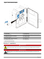
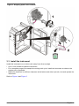
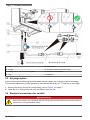
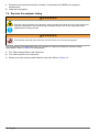
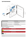
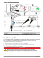
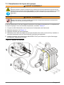
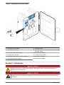
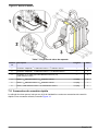
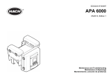
The CA610 Fluoride Analyzer monitors a sample stream continuously for fluoride content. The
analyzer uses an ion-selective electrode (ISE) system to do a test for fluoride in the range of 0.1 to
10 mg/L. Figure 1 shows the main internal components of the analyzer.
6 English

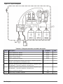
Figure 1 CA610 fluoride analyzer
1 Power switch 8 Keypad/Display
2 Power connections 9 Pinch plate with openings for half-cell electrodes
3 Network and 4–20 mA connections 10 Reagent bottles
4 Air purge, optional 11 Enclosure drain
5 Relay and alarm contact connections 12 Sample inlet
6 Customer access cover 13 Sample drain
7 BNC connectors and valves
Section 3 Installation
D A N G E R
Electrocution hazard. Always remove power to the instrument before making electrical connections.
D A N G E R
Multiple hazards. Only qualified personnel must conduct the tasks described in this section of the
document.
English 7

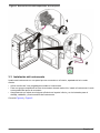
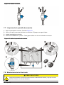
3.1 Product components
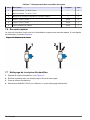
Make sure that all components have been received. Refer to Figure 2. If any items are missing or
damaged, contact the manufacturer or a sales representative immediately.
Figure 2 Product components
1 Analyzer 3 Standard solution, 5.0 mg/L as
F-
5 Installation, maintenance and
half-cell electrode kits
2 Standard solution, 0.5 mg/L as
F-
4 Reagent solution, TISAB
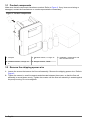
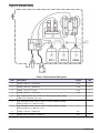
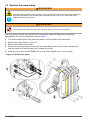
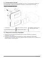
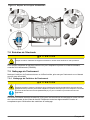
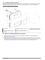
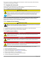
3.2 Remove the shipping spacer wire
1. Loosen the screws that secure the flow cell assembly. Remove the shipping spacer wire. Refer to
Figure 3.
2. Tighten the screws in small increments and alternate between the screws, so that the flow cell
assembly is moved down evenly. Tighten the screws until the flow cell assembly is seated against
the pump housing. Do not overtighten.
8
English

Figure 3 Shipping spacer wire removal
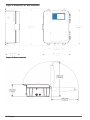
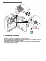
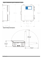
3.3 Install the instrument
Install this instrument on an indoor wall, away from direct sunlight.
• Use ¼-inch screws to install the instrument.
• For a complete purge of the sample line during each cycle, install the instrument as close to the
sample point as possible.
• Make sure that there is sufficient clearance at the bottom and sides to plumb, wire and operate the
instrument.
Refer to Figure 4 and Figure 5.
English
9

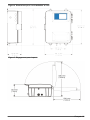
Figure 4 Dimensions for wall installation
Figure 5 Door clearance
10 English

3.4 Plumb the instrument
C A U T I O N
Fire hazard. This product is not designed for use with flammable liquids.
N O T I C E
In the event of spills or leaks from the sample and enclosure drains, some waste may be released. Waste
contains sample and chemical reagents in low concentration. Refer to the reagent MSDS and local regulatory
agencies for correct waste disposal.
Note: Make sure that the enclosure drain is open. The drain must be open to remove sample water if leaks occur.
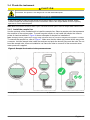
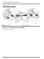
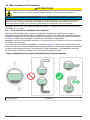
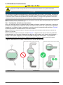
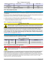
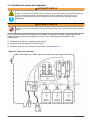
3.4.1 Install the sample line
Use the contents of the installation kit to install the sample line. Select a sample point that represents
the condition of the entire system. To avoid irregular results, do not install the sample line close to
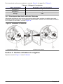
points of chemical additions. Figure 6 shows examples of sample line installations.
Note: Sample pressure greater than 10 psig at the instrument inlet can cause the reagents and sample to overflow.
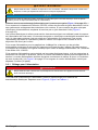
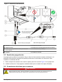
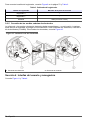
To connect the sample line, refer to Figure 7. Make sure that the tubes are pushed all the way on the
connector. Hold the sample tube inside the analyzer and push the shutoff valve onto the tube. Do not
bend the sample tube. Incorrect installation can cause the tube to come off of the connector when
water pressure is applied.
Figure 6 Sample line location in the process stream
1 Air space 2 Sediment
English 11

Figure 7 Plumbing connections
1 Drain 5 Sample drain
2 Air gap 6 Enclosure drain (must remain open)
3 Tubing, 0.50 in. I.D. (customer-supplied) 7 Installation kit (5742000)
4 Inlet 8 Sample in
3.5 Air purge option
If the environment contains high humidity and/or caustic vapors, an air purge might be necessary.
This process maintains a positive pressure in the instrument with dry air. To connect an air supply:
1. Remove the plug in the quick connect fitting, refer to Figure 1 on page 7.
2. Install the ¼-in. tubing and push until two distinct stops are felt.
3.6 Electrical connections for conduit
D A N G E R
Electrocution hazard. Use only fittings that have the specified environmental enclosure rating. Obey the
requirements in the Specifications section.
12 English

W A R N I N G
Electrocution hazard. Install a 10 A circuit breaker for mains power. Identify the circuit breaker with a
label, as a local disconnect for this equipment.
N O T I C E
Use wire and wiring practices that conform to local, state and national electrical codes. For wet locations, install
the power with a GFIC outlet.
Make all power connections through the conduit opening (Figure 1 on page 7). To maintain the IEC
529 IP62 environmental rating, use liquid-tight sealing-type conduit fittings and cord strain reliefs. If
connections are not made through a conduit opening, install an oil-tight seal in place of the plugs
(Figure 9 on page 14).
Electrical and instrumentation standards require a local method to remove power from the
instrument. The instrument has a power on/off switch that can be accessed without the use of a tool.
An external switch is not required for instrument power. To remove relay power from the instrument,
install an external customer-supplied 5-amp fused switch or a 5-amp breaker.
In hard-wired applications, make sure that the power and safety ground service drops for the
instrument are no longer than 6 meters (20 feet). The exception is when metal conduit is used to
shield the AC power wiring. Use 18 to 12 AWG wire.
If power cords are allowed by local electrical codes, and power surges and transients are not a
concern, use a sealing-type strain relief and power cord. The power cord must have three 18-gauge
conductors (which includes a safety ground wire). Refer to Figure 9 on page 14. The length of the
power cord must not be greater than 3 meters (10 feet).
3.6.1 Wiring for power
D A N G E R
Electrocution hazard. Always remove power to the instrument before making electrical connections.
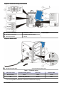
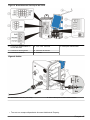
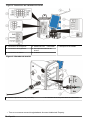
To connect the instrument to power, remove the access cover and make the wiring connections.
Refer to Figure 8, Figure 9 and Table 1.
English
13

Figure 8 Customer wiring connections
1 AC power connections 4 T20 Torx
®
1
driver 7 Power switch
2 Recorder connections 5 Voltage selection switch
3 Alarm connections 6 Fuses
Figure 9 Strain relief
1 Oil-tight seal (4221000) 2 Strain relief for power cord
Table 1 Terminal wiring
Wire color code Protective earth ground Hot or Ø1 Neutral or Ø2
North America Green Black White
IEC Green with yellow line Brown Blue
1
Torx is a registered trademark of Acument Intellectual Property.
14 English

3.6.2 Select the voltage
N O T I C E
To avoid serious damage to the instrument, make sure that the line voltage is set correctly.
The instrument is set to 115-volt operation at the factory. To change the line voltage to 230-volt
operation, refer to the steps that follow.
1. Use a T20 torx wrench to remove the customer access cover.
2. Move the conversion switch to the 230 V position. Figure 8 on page 14 shows the location of the
line voltage selector.
3.6.3 Connect the alarm relays
C A U T I O N
Fire hazard. Relay loads must be resistive. Always limit current to the relays with an external fuse or
breaker. Obey the relay ratings in the Specifications section.
The analyzer can function as sample point alarms (high or low), as a system warning indicator or a
system alarm indicator. The analyzer contains two alarm relays for use with either high voltage
(greater than 30 V-RMS and 42.2 V-PEAK or 60 VDC) or low voltage (less than 30 V-RMS and
42.2 V-PEAK, or less than 60 VDC). Do not configure a combination of both high and low voltage.
For wiring information, refer to Figure 8 on page 14 and Table 2.
N O T I C E
The relay connector accepts 18-12 AWG. The application will determine the wire gauge needed. Wire gauge less
than 18 AWG is not recommended.
Table 2 Relay wiring
Terminal block Terminal 1 Terminal 2 Terminal 3
J1 COM Normally open (NO) Normally closed (NC)
J2 COM Normally open (NO) Normally closed (NC)
3.6.4 Connect the recorder output
D A N G E R
Electrocution hazard. Always remove power to the instrument before making electrical connections.
The recorder output is a 4–20 mA current source output. Use twisted pair shielded wire for the
recorder connections. Use of non-shielded cable may result in radio frequency emission or
susceptibility levels higher than the allowed levels. Connect the shield either at the recorder end or
the analyzer end. Do not connect the shield at both ends of the cable. Wire insulation must be seated
against the connector. Do not leave any of the bare wire exposed.
To connect the recorder output, refer to Figure 8 on page 14 and Table 3.
Table 3 Recorder wiring
Recorder wires Circuit board markings
Recorder + +
Recorder – –
Shield GND
English 15

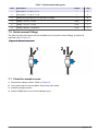
3.6.5 Connect the electrode half-cells
The electrode reference and half-cells must be assembled and then installed before the analyzer will
function. To assemble the electrodes, refer to the Electrode Kit (5744800). To install the electrodes,
refer to Figure 10.
Figure 10 Electrode installation
1 Reference electrode 2 Measuring electrode
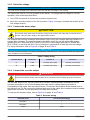
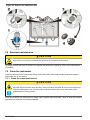
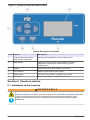
Section 4 User interface and navigation
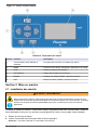
Refer to Figure 11 and Table 4.
16
English

Figure 11 CA610 keypad and display
Table 4 Keypad description
Key Function Description
1 UP, DOWN, RIGHT and LEFT ARROW
keys
Use to navigate the menu or edit values
2 MENU Goes to the Alarm, Recorder, Maintenance and Setup menus.
3 Screen Shows measurement and menu information
4 Alarm LED Shows that alarms are active
5 ENTER Confirms an edited value; menu navigation
6 EXIT Erases an edited value; menu navigation
Section 5 Startup
5.1 Install the reagents
W A R N I N G
Chemical exposure hazard. Obey laboratory safety procedures and wear all of the personal protective
equipment appropriate to the chemicals that are handled. Refer to the current safety data sheets
(MSDS/SDS) for safety protocols.
The analyzer uses three reagents: a total ionic strength adjustment (TISAB) buffer solution and two
fluoride standards. The solutions are formulated at the factory and ready to install.
1. Remove the cap from the bottle.
2. Insert the cap/tubing assembly into the appropriate bottle.
Note: See the label on the cap/tubing assembly.
English
17

3. Tighten the cap on the bottle.
4. Repeat the steps for all three bottles.
5.2 Start the instrument
Note: To avoid back flow of the sample to the reagents, make sure that the pressure plate is securely attached.
1. Open the supply valve to the instrument.
2. Let the pressure in the tubes become stable.
Note: If leaks occur under pressure, examine all the connections. Secure connections until all leaks have
stopped.
3. Look at the bypass flow to the drain and adjust sample flow to the analyzer with the shut off valve.
Set the flow to 200-500 mL/min.
4. Turn on the power.
5. Select Prime>Prime All to do a prime cycle. Refer to Prime settings on page 20. When the
prime cycle is complete, the initial readings might not be accurate.
6. If the readings are not accurate, let the readings stabilize (1-12 hours) and then calibrate the
analyzer.
Note: In single-relay systems, the relay tube is active during this time.
Section 6 Operation
6.1 Use the menus
To enter any menu, push MENU. Use the arrow buttons to select an option, then push ENTER. Edit
a value when it flashes. Use the arrow buttons to change the digits. Push ENTER to move to the next
editable digit. To exit from any menu structure, push EXIT until the MENU button is no longer turned
on. The display shows the current function and the last measured value.
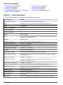
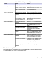
6.2 Setup options
1. Go to the Setup menu.
2. Set the options.
Option Description
Language English (default), Spanish, French and German
Hold Outputs Displays/edits current status of Hold Outputs. If ON is selected, all alarms are disabled
and the recorder output level is held at its current level. The Alarm LED flashes. The
alarm lockout period is disabled after 30 minutes or if OFF is selected.
Diag Output On or Off. Push EXIT to reject changes and return to setup. If Diag Output is on and the
optional Hach network interface is present, additional diagnostic data is sent via an SIO.
If the Hach network interface is present, the instrument outputs readings to an
AquaTrend Interface or MOD I/O regardless of the Diag Output setting.
Keyboard
Lockout
On or Off. If the keyboard is locked out, no editing functions are allowed and all
changeable settings are disabled except Keyboard Lockout. Default is Off.
Reaction Time Sets the reaction delay time. This value is set at 200 seconds to let the instrument to
correctly measure fluoride in the presence of interferences such as aluminum. This time
can be further decreased if metals which typically include complex fluoride (including Al
and Fe) are not present. If the delay is removed, it causes low fluoride readings in the
presence of metals. For example, if 1 mg/L of Al is present, a 1 mg/L sample of fluoride
reads 0.3 mg/L at no delay and 0.6 mg/L with a 60 second delay. If the delay time is
changed, it affects reagent consumption.
Pwr Fail Warning Sets the power fail warning to On or Off. Press ENTER then use the arrow keys to
toggle between ON and OFF. Press ENTER to select. Press EXIT to reject changes and
return to Setup. If the power fail warning is already on and the power is interrupted, a
system warning will be triggered when power is turned on.
18 English

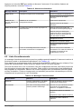
Option Description
Correction Allows entry of a correction factor (a positive or negative value) that can be added to an
analyzer measurement.
Default Settings Sets the instrument to factory defaults. All user-specified settings are lost.
Cell Potential Differential voltage reading from the electrodes.
Celsius Shows temperature of the flow cell.
Reaction Delay Shows the amount of the reaction delay that has elapsed.
PWM Setting Heater drive level (0–250).
Relay Test For two-relay systems: Alternates between ALARM 1 (and the alarm LED illuminated)
and ALARM 2 only. For single-relay systems: ALARM 1 (and the alarm LED illuminated).
Recrdr Test
Rec Min: Sets Recorder output to 4 mA; Rec Mid: Sets Recorder output to 12 mA; Rec
Max: Sets Recorder output to 20 mA
Valve Test Energizes Valve 1 or Valve 2.
Display Test Displays all LCD segments for 10 seconds.
6.3 Calibrate the instrument
The instrument does a self-calibration which takes approximately 53 minutes. To set up the
calibration options:
1. Go to the Calibration menu.
2. Set the options.
Option Description
Cal Time Sets the time interval between automatic calibrations. The default is 24 hours. The analyzer
automatically calibrates after the calibration time interval expires. The calibration time interval
starts when the analyzer is turned on or when the calibration time interval setting is changed.
Power loss restarts the calibration time interval. On single-relay systems, the CAL relay is active
during the auto-calibration.
Calib Push ENTER to do a calibration. On single-relay systems, the CAL relay is active.
Default Cal Sets the slope to -58.0 mV; Offset to -15.0 mV; Std 1 to 0.5 mg/L; Std 2 to 5.0 mg/L, and Cal
Time to 24 hours.
Std 1 Sets the value if a different standard is selected for special sampling circumstances.
Std 2 Sets the value if a different standard is selected for special sampling circumstances.
Cal Pt1 Use this value to identify the drift of the electrodes since the previous calibration.
Cal Pt2 Use this value to identify the drift of the electrodes since the previous calibration.
Offset Shows the current offset correction factor. This factor is calculated during calibration. Typical
values are between -100 mV and +100 mV.
Slope Shows the current slope value. Typical values are -53 to -63 mV/decade. New electrodes might
have a slope that is -40 to -50 mV/decade. As the electrode conditions stabilize, the slope value
(calculated during calibration) rises.
English 19

6.4 Prime settings
1. Go to the Prime menu.
2. Set the options.
Option Description
Sample Stops the current cycle and starts 90 sequential pump cycles to prime the sample line. For single-
relay systems, the CAL relay is active.
Std1 Stops the current cycle. Primes Standard 1 with 90 cycles then 90 cycles of sample. For single-
relay systems, the CAL relay is active.
Std2 Stops the current cycle. Primes Standard 2 with 90 cycles then 90 cycles of sample. For single-
relay systems, the CAL relay is active.
All Stops the current cycle. Primes Standard 1 (90 cycles), Standard 2 (90 cycles), and then 90 cycles
of reagent. For single-relay systems, the CAL relay is active.
6.5 Set the alarms
1. Go to the Alarms menu.
2. Set the options for Alarm 1 and Alarm 2.
Option Description
Type Select either high or low.
Setpt Sets the alarm set point to 0.0 to 10.0.
Syswarn Sets the relay to be activated on system warning.
Note: Not available on single-relay systems.
Sysalm Sets the relay to be activated on system alarm.
Note: Not available on single-relay systems.
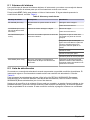
6.6 Set the recorder values
1. Go to the Recorder menu.
2. Set the following options.
Option Description
Low Sets the low limit: 0.0 to 10.0 mg/L limits; 0.0 is the default
High Sets the high limit: 0.0 to 10.0 mg/L limits; 10.0 is the default
On System Alarm Sets the recorder fail mode on a system alarm: go to the low value, go to the high value,
or hold the current value. The default setting is for the recorder output to go to the low
value.
Lo Adj Sets the minimum current level of recorder output: 0 to 300 D/A counts.
Hi Adj Sets the maximum current level of recorder output: 800 to 1024 D/A counts.
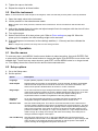
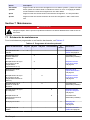
Section 7 Maintenance
D A N G E R
Multiple hazards. Only qualified personnel must conduct the tasks described in this section of the
document.
20 English
La page est en cours de chargement...
La page est en cours de chargement...
La page est en cours de chargement...
La page est en cours de chargement...
La page est en cours de chargement...
La page est en cours de chargement...
La page est en cours de chargement...
La page est en cours de chargement...
La page est en cours de chargement...
La page est en cours de chargement...
La page est en cours de chargement...
La page est en cours de chargement...
La page est en cours de chargement...
La page est en cours de chargement...
La page est en cours de chargement...
La page est en cours de chargement...
La page est en cours de chargement...
La page est en cours de chargement...
La page est en cours de chargement...
La page est en cours de chargement...
La page est en cours de chargement...
La page est en cours de chargement...
La page est en cours de chargement...
La page est en cours de chargement...
La page est en cours de chargement...
La page est en cours de chargement...
La page est en cours de chargement...
La page est en cours de chargement...
La page est en cours de chargement...
La page est en cours de chargement...
La page est en cours de chargement...
La page est en cours de chargement...
La page est en cours de chargement...
La page est en cours de chargement...
La page est en cours de chargement...
La page est en cours de chargement...
La page est en cours de chargement...
La page est en cours de chargement...
La page est en cours de chargement...
La page est en cours de chargement...
La page est en cours de chargement...
La page est en cours de chargement...
La page est en cours de chargement...
La page est en cours de chargement...
La page est en cours de chargement...
La page est en cours de chargement...
La page est en cours de chargement...
La page est en cours de chargement...
La page est en cours de chargement...
La page est en cours de chargement...
La page est en cours de chargement...
La page est en cours de chargement...
La page est en cours de chargement...
La page est en cours de chargement...
La page est en cours de chargement...
La page est en cours de chargement...
La page est en cours de chargement...
La page est en cours de chargement...
La page est en cours de chargement...
La page est en cours de chargement...
La page est en cours de chargement...
La page est en cours de chargement...
La page est en cours de chargement...
La page est en cours de chargement...
La page est en cours de chargement...
La page est en cours de chargement...
La page est en cours de chargement...
La page est en cours de chargement...
La page est en cours de chargement...
La page est en cours de chargement...
La page est en cours de chargement...
La page est en cours de chargement...
-
 1
1
-
 2
2
-
 3
3
-
 4
4
-
 5
5
-
 6
6
-
 7
7
-
 8
8
-
 9
9
-
 10
10
-
 11
11
-
 12
12
-
 13
13
-
 14
14
-
 15
15
-
 16
16
-
 17
17
-
 18
18
-
 19
19
-
 20
20
-
 21
21
-
 22
22
-
 23
23
-
 24
24
-
 25
25
-
 26
26
-
 27
27
-
 28
28
-
 29
29
-
 30
30
-
 31
31
-
 32
32
-
 33
33
-
 34
34
-
 35
35
-
 36
36
-
 37
37
-
 38
38
-
 39
39
-
 40
40
-
 41
41
-
 42
42
-
 43
43
-
 44
44
-
 45
45
-
 46
46
-
 47
47
-
 48
48
-
 49
49
-
 50
50
-
 51
51
-
 52
52
-
 53
53
-
 54
54
-
 55
55
-
 56
56
-
 57
57
-
 58
58
-
 59
59
-
 60
60
-
 61
61
-
 62
62
-
 63
63
-
 64
64
-
 65
65
-
 66
66
-
 67
67
-
 68
68
-
 69
69
-
 70
70
-
 71
71
-
 72
72
-
 73
73
-
 74
74
-
 75
75
-
 76
76
-
 77
77
-
 78
78
-
 79
79
-
 80
80
-
 81
81
-
 82
82
-
 83
83
-
 84
84
-
 85
85
-
 86
86
-
 87
87
-
 88
88
-
 89
89
-
 90
90
-
 91
91
-
 92
92


dans d''autres langues
- English: Hach CA610 User manual
- español: Hach CA610 Manual de usuario
Documents connexes
-
 Hach 5500sc SiO2 Guide d'installation
-
 Hach Polymetron 9611sc Guide d'installation
-
Hach CL17sc Manuel utilisateur
-
 Hach 5500sc Maintenance And Troubleshooting Manual
-
Hach SP-510 Basic User Manual
-
-
 Hach Lange APA 6000 Maintenance And Troubleshooting Manual
-
 Hach 5500sc Operations
-
 Hach Lange astroTOC Basic User Manual
-
 Hach APA 6000 Manuel utilisateur