
DW077
Rotary Laser
Laser rotatif
Láser rotativo
INSTRUCTION MANUAL
GUIDE D'UTILISATION
MANUAL DE INSTRUCCIONES
INSTRUCTIVO DE OPERACIÓN, CENTROS DE SERVICIO Y PÓLIZA
DE GARANTÍA. ADVERTENCIA: LÉASE ESTE INSTRUCTIVO
ANTES DE USAR EL PRODUCTO.
If you have questions or comments, contact us.
Pour toute question ou tout commentaire, nous contacter.
Si tiene dudas o comentarios, contáctenos.
1-800-4-DEWALT • www.dewalt.com


English
1
IF YOU HAVE ANY QUESTIONS OR COMMENTS ABOUT THIS
OR ANY D
EWALT TOOL, CALL US TOLL FREE AT:
1-800-4-D
EWALT (1-800-433-9258)
WARNING! Read and understand all instructions.
Failure to follow all instructions listed below may result
in electric shock, fire and/or serious personal injury.
SAVE THESE INSTRUCTIONS
Safety Instructions for Lasers
• Do not operate the laser in explosive atmospheres, such as
in the presence of flammable liquids, gases, or dust. Power
tools create sparks which may ignite the dust or fumes.
• Use the laser only with the specifically designated batter-
ies. Use of any other batteries may create a risk of fire.
• Store idle laser out of reach of children and other untrained
persons. Lasers are dangerous in the hands of untrained users.
• Use only accessories that are recommended by the manu-
facturer for your model. Accessories that may be suitable for
one laser, may create a risk of injury when used on another laser.
• Tool service must be performed only by qualified repair
personnel. Service or maintenance performed by unquali-
fied personnel may result in injury. To locate your nearest
D
E
WALT service center call 1-800-4-D
E
WALT (1-800-433-9258)
or go to http://www.dewalt.com on the Internet.
• Do not use optical tools such as a telescope or transit to
view the laser beam. Serious eye injury could result.
• Do not place the laser in a position which may cause any-
one to intentionally or unintentionally stare into the laser
beam. Serious eye injury could result
• Turn the laser off when it is not in use. Leaving the laser on
increases the risk of staring into the laser beam.
• Repairs and servicing MUST be performed by a qualified
repair facility. Repairs performed by unqualified personnel
could result in serious injury.
• Do not disassemble the laser tool. There are no user serv-
iceable parts inside.
• Do not operate the laser around children or allow children
to operate the laser. Serious eye injury may result.
• Do not remove or deface warning labels. If labels are
removed user or others may inadvertently expose themselves to
radiation.
• Position the laser securely on a level surface. Damage to the
laser or serious injury could result if the laser falls.
• Dress properly. Do not wear loose clothing or jewelry.
Contain long hair. Keep your hair, clothing, and gloves
away from moving parts. Loose clothing, jewelry, or long hair
can be caught in moving parts. Air vents often cover moving
parts and should also be avoided.
CAUTION - Use of controls or adjustments or performance
of procedures other than those specified herein may result in
hazardous radiation exposure.
WARNING! DO NOT DISASSEMBLE THE ROTARY LASER.
There are no user serviceable parts inside. Disassembling the
rotary laser will void all warranties on the product. Do not
modify the product in any way. Modifying the tool may result in
hazardous laser radiation exposure.
• The label on your tool may include the following symbols.
V......................volts
mW ................milliwatts
..............laser warning symbol
nm ..................wavelength in nanometers
IIIa ..................Class IIIa Laser

English
2
• For your convenience and safety, the following labels are on
your laser.
AVOID EXPOSURE : LASER RADIATION IS EMITTED
FROM THIS APERTURES.
DANGER: LASER RADIATION. AVOID DIRECT EYE
EXPOSURE.
Laser Information
The DW077 Cordless Rotary Laser is listed as a CLASS IIIA
LASER PRODUCT and complies with the applicable requirement
of title 21 of the Code of Federal Regulations set forth by: the
Department of Health, Education, and Welfare; the Food and Drug
Administration; the Center for Devices and Radiological Health.
These devices comply with Part 15 of the FCC Rules. Operation is
subject to the following two conditions: (1) this device may not
cause harmful interference, and (2) this device must accept any
interference received, including interference that may cause unde-
sired operation.
NOTE: This equipment has been tested and found to comply with
the limits for a Class B digital device, pursuant to Part 15 of the FCC
Rules. These limits are designed to provide reasonable protection
against harmful interference in a residential installation. This equip-
ment generates, uses and can radiate radio frequency energy and,
if not installed and used in accordance with the instructions, may
cause harmful interference to radio communications. However,
there is no guarantee that interference will not occur in a particular
installation. If this equipment does cause harmful interference to
radio and television reception, which can be determined by turning
the equipment off and on, the user is encouraged to try to correct the
interference by one or more of the following measures:
• Reorient or relocate the receiving antenna.
• Increase the separation between the equipment and receiver.
• Connect the equipment into an outlet on a circuit differentfrom
that which the receiver is connected.
• Consult the dealer or an experienced radio/TV technician for
help.
These Class B digital devices comply with Canadian ICES-003.
Important Safety Instructions for
Battery Packs
Your tool uses a 9.6, 12.0, 14.4 or an 18 Volt DEWALT battery pack.
When ordering replacement battery packs, be sure to include cata-
log number and voltage. Extended Run-Time battery packs deliver
more run-time than standard battery packs. Consult the chart at the
end of this manual for compatibility of chargers and battery packs.
NOTE: Your tool will accept either standard or Extended Run Time
battery packs. However, be sure to select proper voltage. Batteries
slowly lose their charge when they are not on the charger, the best
place to keep your battery is on the charger at all times.

English
3
The battery pack is not fully charged out of the carton. Before using
the battery pack and charger, read the safety instructions below.
Then follow charging procedures outlined.
READ ALL INSTRUCTIONS
• Do not incinerate the battery pack even if it is severely dam-
aged or is completely worn out. The battery pack can explode
in a fire.
• A small leakage of liquid from the battery pack cells may
occur under extreme usage or temperature conditions. This
does not indicate a failure. However, if the outer seal is broken
and this leakage gets on your skin:
a. Wash quickly with soap and water.
b. Neutralize with a mild acid such as lemon juice or vinegar.
c. If battery liquid gets into your eyes, flush them with clean
water for a minimum of 10 minutes and seek immediate med-
ical attention. (Medical note: The liquid is 25-35% solution of
potassium hydroxide.)
• Charge the battery packs only in D
E
WALT chargers.
• DO NOT splash or immerse in water or other liquids.
• Do not store or use the tool and battery pack in locations
where the temperature may reach or exceed 105°F (40˚)
(such as outside sheds or metal buildings in summer).
DANGER: Electrocution hazard. Never attempt to open the bat-
tery pack for any reason. If battery pack case is cracked or dam-
aged, do not insert into charger. Electric shock or electrocution may
result. Damaged battery packs should be returned to service cen-
ter for recycling.
NOTE: Battery storage and carrying caps are provided
for use whenever the battery is out of the tool or charger.
Remove cap before placing battery in charger or tool.
WARNING: Fire hazard. Do not store or carry
battery so that metal objects can contact exposed
battery terminals. For example, do not place battery in aprons,
pockets, tool boxes, product kit boxes, drawers, etc., with loose
nails, screws, keys, etc. without battery cap. Transporting batter-
ies can possibly cause fires if the battery terminals inadver-
tently come in contact with conductive materials such as
keys, coins, hand tools and the like. The US Department of
Transportation Hazardous Material Regulations (HMR) actually
prohibit transporting batteries in commerce or on airplanes (i.e.,
packed in suitcases and carry-on luggage) UNLESS they are prop-
erly protected from short circuits. So when transporting individual
batteries, make sure that the battery terminals are protected and
well insulated from materials that could contact them and cause a
short circuit.
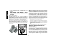
The RBRC™ Seal
The RBRC™ (Rechargeable Battery Recycling
Corporation) Seal on the nickel-cadmium battery (or
battery pack) indicates that the costs to recycle the bat-
tery (or battery pack) at the end of its useful life have
already been paid by D
EWALT. In some areas, it is ille-
gal to place spent nickel-cadmium batteries in the trash or municipal
solid waste stream and the RBRC program provides an environ-
mentally conscious alternative.
RBRC in cooperation with D
EWALT and other battery users, has
established programs in the United States to facilitate the collection
of spent nickel-cadmium batteries. Help protect our environment
and conserve natural resources by returning the spent nickel-cad-
mium battery to an authorized D
EWALT service center or to your
local retailer for recycling. You may also contact your local recycling
center for information on where to drop off the spent battery.
RBRC™ is a registered trademark of the
Rechargeable Battery
Recycling Corporation.

English
4
Important Safety Instructions for
Battery Chargers
SAVE THESE INSTRUCTIONS: This manual contains important
safety instructions for battery chargers.
• Before using charger, read all instructions and cautionary mark-
ings on charger, battery pack, and product using battery pack.
DANGER: Electrocution hazard. 120 volts are present at charg-
ing terminals. Do not probe with conductive objects. Electric shock
or electrocution may result.
WARNING: Shock hazard. Do not allow any liquid to get inside
charger. Electric shock may result.
CAUTION: Burn hazard. To reduce the risk of injury, charge only
D
E
WALT nickel cadmium rechargeable batteries. Other types of
batteries may burst causing personal injury and damage.
CAUTION: Under certain conditions, with the charger plugged in
to the power supply, the exposed charging contacts inside the
charger can be shorted by foreign material. Foreign materials of a
conductive nature such as, but not limited to, steel wool, aluminum
foil, or any buildup of metallic particles should be kept away from
charger cavities. Always unplug the charger from the power supply
when there is no battery pack in the cavity. Unplug charger before
attempting to clean.
• DO NOT attempt to charge the battery pack with any charg-
ers other than the ones in this manual. The charger and bat-
tery pack are specifically designed to work together.
• These chargers are not intended for any uses other than
charging D
E
WALT rechargeable batteries. Any other uses
may result in risk of fire, electric shock or electrocution.
• Do not expose charger to rain or snow.
• Pull by plug rather than cord when disconnecting charger.
This will reduce risk of damage to electric plug and cord.
• Make sure that cord is located so that it will not be stepped
on, tripped over, or otherwise subjected to damage or
stress.
• Do not use an extension cord unless it is absolutely neces-
sary. Use of improper extension cord could result in risk of fire,
electric shock, or electrocution.
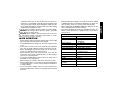
• An extension cord must have adequate wire size (AWG or
American Wire Gauge) for safety. The smaller the gauge
number of the wire, the greater the capacity of the cable, that is
16 gauge has more capacity than 18 gauge. When using more
than one extension to make up the total length, be sure each
individual extension contains at least the minimum wire size.
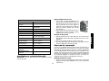
Recommended Minimum Wire Size for Extension Cords
Total Length of Cord
25 ft. 50 ft. 75 ft. 100 ft. 125 ft. 150 ft. 175 ft.
7.6 m 15.2 m 22.9 m 30.5 m 38.1 m 45.7 m 53.3 m
Wire Size AWG
18 18 16 16 14 14 12
• Do not place any object on top of charger or place the
charger on a soft surface that might block the ventilation
slots and result in excessive internal heat. Place the charg-
er in a position away from any heat source. The charger is ven-
tilated through slots in the top and the bottom of the housing.
• Do not operate charger with damaged cord or plug — have
them replaced immediately.
• Do not operate charger if it has received a sharp blow, been
dropped, or otherwise damaged in any way. Take it to an
authorized service center.
• Do not disassemble charger; take it to an authorized service
center when service or repair is required. Incorrect reassem-
bly may result in a risk of electric shock, electrocution or fire.

English
5
• Disconnect the charger from the outlet before attempting
any cleaning. This will reduce the risk of electric shock.
Removing the battery pack will not reduce this risk.
• NEVER attempt to connect 2 chargers together.
• The charger is designed to operate on standard household
electrical power (120 Volts). Do not attempt to use it on any
other voltage. This does not apply to the vehicular charger.
Using Automatic Tune-Up™ Mode
The automatic Tune-Up™ Mode equalizes or balances the individ-
ual cells in the battery pack allowing it to function at peak capacity.
Battery packs should be tuned up weekly or after 10 charge/dis-
charge cycles or whenever the pack no longer delivers the same
amount of work. To use the automatic Tune-Up™, place the battery
pack in the charger and leave it for at least 8 hours. The charger
will cycle through the following modes.
1. The red light will blink continuously indicating that the 1-hour
charge cycle has started.
2. When the 1-hour charge cycle is complete, the light will stay on
continuously and will no longer blink. This indicates that the
pack is fully charged and can be used at this time.
3. If the pack is left in the charger after the initial 1-hour charge,
the charger will begin the Automatic Tune-Up mode. This mode
continues up to 8 hours or until the individual cells in the battery
pack are equalized. The battery pack is ready for use and can
be removed at any time during the Tune-Up mode.
4. Once the Automatic Tune Up mode is complete, the charger will
begin a maintenance charge; the red indicator will remain lit.
SAVE THESE INSTRUCTIONS FOR
FUTURE USE
Chargers
Your tool uses a DEWALT charger. Your battery can be charged in
D
EWALT 1 Hour Chargers, 15 Minute Chargers or Vehicular 12 Volt
Charger. Be sure to read all safety instructions before using your
charger. Consult the chart at the end of this manual for compatibili-
ty of chargers and battery packs.
Charging Procedure
DANGER: Electrocution hazard. 120 volts present at charging
terminals. Do not probe with conductive objects. Danger of electric
shock or electrocution.
1. Plug the charger into an appropriate outlet before inserting bat-
tery pack.
2. Insert the battery pack into the charger, making sure the pack
is fully seated. The red (charging) light will blink continuously
indicating that the charging process has started.
3. The completion of charge will be indicated by the red light
remaining ON continuously. The pack is fully charged and may
be used at this time or left in the charger.
Indicator Light Operation
Charge Indicators
Some chargers are designed to detect certain problems that can
arise with battery packs. Problems are indicated by the red light
flashing at a fast rate. If this occurs, re-insert battery pack into the
charger. If the problem persists, try a different battery pack to deter-

English
6
mine if the charger is OK. If the new pack charges correctly, then the
original pack is defective and should be returned to a service center
or other collection site for recycling. If the new battery pack elicits the
same trouble indication as the original, have the charger tested at
an authorized service center.
HOT/COLD PACK DELAY
Some chargers have a Hot/Cold Pack Delay feature: when the
charger detects a battery that is hot, it automatically starts a Hot
Pack Delay, suspending charging until the battery has cooled. After
the battery has cooled, the charger automatically switches to the
Pack Charging mode. This feature ensures maximum battery life.
The red light flashes long, then short while in the Hot Pack Delay
mode.
PROBLEM POWER LINE
Some chargers have a Problem Power Line indicator. When the
charger is used with some portable power sources such as genera-
tors or sources that convert DC to AC, the charger may temporarily
suspend operation, flashing the red light with two fast blinks fol-
lowed by a pause. This indicates the power source is out of limits.
LEAVING THE BATTERY PACK IN THE CHARGER
The charger and battery pack can be left connected with the red
light glowing indefinitely. The charger will keep the battery pack
fresh and fully charged.
NOTE: A battery pack will slowly lose its charge when kept out of
the charger. If the battery pack has not been kept on maintenance
charge, it may need to be recharged before use. A battery pack
may also slowly lose its charge if left in a charger that is not plugged
into an appropriate AC source.
WEAK BATTERY PACKS: Chargers can also detect a weak bat-
tery. Such batteries are still usable but should not be expected to
perform as much work. In such cases, about 10 seconds after bat-
tery insertion, the charger will beep rapidly 8 times to indicate a
weak battery condition. The charger will then go on to charge the
battery to the highest capacity possible.
Important Charging Notes
1. Longest life and best performance can be obtained if the bat-
tery pack is charged when the air temperature is between 65°F
and 75°F (18°- 24°C). DO NOT charge the battery pack in an
air temperature below +40°F (+4.5°C), or above +105°F
(+40.5°C). This is important and will prevent serious damage to
the battery pack.
2. The charger and battery pack may become warm to touch
while charging. This is a normal condition, and does not indi-
cate a problem. To facilitate the cooling of the battery pack after
use, avoid placing the charger or battery pack in a warm envi-
ronment such as in a metal shed, or an uninsulated trailer.
3. If the battery pack does not charge properly:
a. Check current at receptacle by plugging in a lamp or other
appliance
b. Check to see if receptacle is connected to a light switch
which turns power off when you turn out the lights.
c. Move charger and battery pack to a location where the sur-
rounding air temperature is approximately 65°F - 75°F (18°-
24°C).
d. If charging problems persist, take the tool, battery pack and
charger to your local service center.
4. The battery pack should be recharged when it fails to produce
sufficient power on jobs which were easily done previously. DO
NOT CONTINUE to use under these conditions. Follow the
charging procedure. You may also charge a partially used pack
whenever you desire with no adverse affect on the battery pack.
5. Under certain conditions, with the charger plugged into the
power supply, the exposed charging contacts inside the charger
can be shorted by foreign material. Foreign materials of a

English
7
conductive nature such as, but not limited to, steel wool, alu-
minum foil, or any buildup of metallic particles should be kept
away from charger cavities. Always unplug the charger from the
power supply when there is no battery pack in the cavity. Unplug
charger before attempting to clean.
6. Do not freeze or immerse charger in water or any other liquid.
WARNING: Shock hazard. Don’t allow any liquid to get inside
charger. Electric shock may result.
CAUTION: Never attempt to open the battery pack for any rea-
son. If the plastic housing of the battery pack breaks or cracks,
return to a service center for recycling.
LASER OPERATION
• Ensure that the battery is properly charged. If the “Power” LED
light is flashing, the battery needs to be charged.
• To extend battery life per charge, turn the laser off when it is not
in use.
• To ensure the accuracy of your work, check the laser calibration
often. See the “Field Calibration Check” section of this manual.
• Before attempting to use the laser, make sure the tool is posi-
tioned on a relatively smooth,secure surface.
• Always mark the center of the laser line or dot. If you mark dif-
ferent parts of the beam at different times you will introduce
error into your measurements.
• To increase working distance and accuracy, set up the laser in
the middle of your working area.
• When attaching to a tripod or wall, mount the laser securely.
• When working indoors, a slow rotary head speed will produce
a visibly brighter line, a faster rotary head speed will produce
a visibly solid line.
• To increase beam visibility, wear the Laser Enhancement
Glasses provided and/or use the Laser Target Card to help find
the beam.
• Extreme temperature changes can cause movement or shifting
of building structures, metal tripods, equipment, etc.,which can
effect accuracy. Check your accuracy often while working.
• When working with the D
EWALT Digital Laser Detector, set the
laser’s rotation speed to the fastest setting.
• If the laser is dropped or has suffers a sharp blow, have the cal-
ibration system checked by a qualified service center before
using the laser.
SPECIFICATIONS
Light Source Semiconductor laser diode
Laser Wavelength 630 – 680nm Visible
Laser Power <5mw, CLASS IIIa LASER
PRODUCT
Rotation Speed 0 – 800 rpm
Self-Leveling Range ± 5°
Indoor Visible Range 200' (61m) diameter
Range with Detector 1500' (450m) diameter
Level Accuracy ± 1/8" per 100'
(± 3mm per 31m)
Power Source 9.6V–18V DEWALT batteries
Operating Temperature 23°F to 122°F (-5°C to 50°C)
Storage Temperature -4°F to 158°F (-20°C to 70°C)
Usage Indoor
Altitude Up to 6560' (2000m)
Maximum Relative 95%
Humidity
Rated Pollution Degree 2

English
8
Installing and Removing the
Battery Pack
NOTE: Make sure your battery pack is fully charged before you
install it.
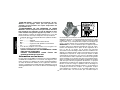
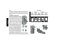
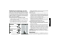
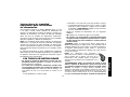
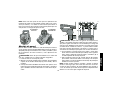
INSTALLING THE BATTERY PACK
1. Rotate the battery adapter plate (A) so that
the applicable cut out for 9.6, 12, 14.4 volt
pack or the 18 volt pack is aligned with the
battery contacts facing the inside of the cut
out.
2. Slide the battery pack in firmly until you
hear the battery pack lock in place.
REMOVING THE BATTERY PACK
1. Push the battery in slightly, press the release buttons, and
firmly pull the battery pack out of the receptacle.
2. The battery ejector pin (D) will aid in removing the pack.
3. To recharge the battery pack, insert it into the charger as
described in the charger section of this manual.
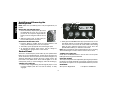
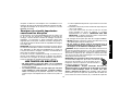
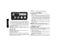
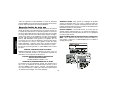
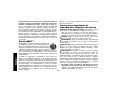
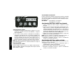
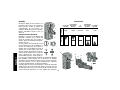
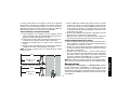
Control Panel
The laser is controled by the power button (E), the speed/rotation
button (F), the scan mode button (G), and two arrows (H and I). The
arrows control the movement of the laser head left and right or up
and down depending on whether the laser is being used in the
level mode or the plumb mode. Three indicator lights are on the
control panel, power (J), X-axis leveling (K), and Y-axis leveling (L).
TURNING THE LASER ON
1. Insert the fully charged battery pack through the proper cut out
in battery adapter plate. Be sure that the battery is firmly
engaged.
D
A
2. Gently press the ON/OFF button (E) to power the laser on. The
laser diode will turn on and the power LED Light (J) will illumi-
nate. If the laser is out of level, the X-axis and/or Y-axis leveling
lights (K and L) will flash until the laser is level. Press the
speed/rotation button (F) to make the head rotate.
NOTE: The head will only rotate momentarily if the laser is leveling.
The head will begin or resume rotation once the laser is level.
TURNING THE LASER OFF
Gently press the ON/OFF button to turn the laser off. The power
LED Light will no longer be illuminated.
ROTATION SPEEDS
The rotary head speed can be adjusted by pressing the speed/rota-
tion button. The head speed will cycle through 4 speeds and stop,
then repeat the sequence as the speed/rotation button is pressed.
REMEMBER:
Slow speed = Bright Beam Fast Speed = Solid Beam
E
F
G
H
I
J K L

9
English
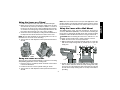
Using the Laser on a Tripod
1. Position the tripod securely and set it to the desired height.
2. Make sure that the top of the tripod is roughly level. the laser
will self-level only if the top of the tripod is within ± 5˚ of level. If
the laser is set up too far out of level, it will beep when it reach-
es the limit of its leveling range. No damage will be done to the
laser, but it will not operate in an “out of level” condition.
3. Secure the laser to the tripod by screwing the threaded knob on
the tripod into the female thread on the bottom of the laser.
NOTE: Be sure that the tripod you are working with has a 5/8"–11
threaded screw to ensure secure mounting.
4. Turn the laser on and adjust the rotation speed and controls as
desired.
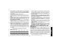
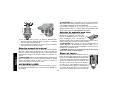
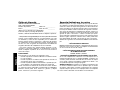
Using the Laser on a Floor
The laser level can be positioned directly on the floor for leveling
and plumbing applications such as framing walls.
1. Place the laser on a relatively smooth and level surface where
it will not be disturbed.
2. Position the laser for a level or plumb setting as shown.
3. Turn the laser on and adjust the rotation speed and controls as
desired.
LEVEL
MODE
PLUMB
MODE
NOTE: The laser will be easier to set up for wall applications if the
rotation speed is set to 0 rpms and if the remote control is used to
line up the laser with control marks. The remote allows one person
to set up the laser.
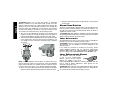
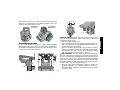
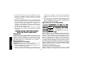
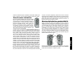
Using the Laser with a Wall Mount
The DW077 Rotary Laser has been designed to work with an
accessory Wall Mount (DW0770). It can be used for attaching the
tool to track or celing angle (mould) and to aid in acoustical ceiling
installation. Follow the directions below for using the wall mount.
CAUTION: Before attaching the laser level to wall track or ceil-
ing angle, be sure that the track or angle is properly secured.
1. Attach the Laser to the accessory wall mount.
2. With the wall mount measuring scale (O) facing you, rotate the
wall mount clamp locking knob (P) towards you to open the
clamp jaws.
3. Position the clamp jaws around the wall track or ceiling angle
and as shown rotate the wall mount clamp locking knob away
from you to close the clamp jaws shut on the track. Be sure that
the wall mount clamp locking knob is securely locked before
proceding.
P
Q
O
P

English
10
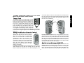
CAUTION: Always use a ceiling wire hanger or equivalent
material, in addition to the wall mount clamp, to help secure the
laser level while mounting it to a wall. Thread the wire through the
handle of the laser level. DO NOT thread the wire through the
protective metal cage. Additionally, screws may be used to fasten
the wall mount directly to the wall as a back up. Screw holes (Q)
are located in the wall mount next to the measuring scales.
4. The tool can be adjusted up and down to the desired offset
height for working. To change the height, loosen the Rack ‘N
Pinion locking knob (R) located on the left of the wall mount.
5. Turn the Rack ‘N Pinion adjustment knob (S) located to the right
of the wall mount to move the laser level up and down to set
your height. Use the wall mount measuring scale to pinpoint
your mark.
NOTE: It may be helpful to turn the power on and turn the rotary
head so that it puts a dot on one of the laser scales. The D
EWALT
target card is marked at 1-1/2" (38mm), therefore, it may be easiest
to set the offset of the laser to 1-1/2" (38mm) below the wall angle.
6. Once you have positioned the laser at the desired offset height,
tighten the Rack ‘N Pinion locking knob to maintain the offset.
R
S
T
7. Using the base leveling knob (T) approximate a level position
from the wall.
Manual Head Rotation
The laser is designed with a protective alloy cage around the rotary
head to prevent accidental damage from work site activities. You
can still access the rotary head and manually direct the beam to
extablish or transfer a mark.
CAUTION: DO NOT attempt to manually rotate the head while
it is spinning. Manual head rotation should only be performed when
the laser is being used in dot mode (0 rpm).
Laser Accessories
Recommended accessories for use with your tool are available for
purchase at your factory-owned local service center.
CAUTION: The use of any non-recommended accessory may
be hazardous. Use only D
E
WALT accessories designed for use
with this product.
If you need any assistance in locating any accessory, please
contact D
EWALT Industrial Tool Co., 701 East Joppa Road,
Baltimore, MD 21286 or call 1-800-4-D
EWALT. (1-800-433-9258)
See our catalog on the World Wide Web at www.DEWALT.com.
Laser Enhancement Glasses
The DEWALT Laser Kit includes
a pair of Laser Enhancement
Glasses. These red lens glasses
improve the visibility of the laser
beam under bright light conditions or over long distances when the
laser is used for interior applications. These glasses are not
required to operate the laser.
CAUTION: These glasses are not ANSI approved safety glasses
and should not be worn while operating other tools. These glasses
do not keep the laser beam from entering your eyes.

English
11
DANGER: NEVER STARE DIRECTLY INTO THE LASER
BEAM, WITH OR WITHOUT THESE GLASSES.
Target Card
The DEWALT Rotary Laser Kit includes a Laser
Target Card to aid in locating and marking the laser
beam. The target card enhances the visibility of the
laser beam as the beam crosses over the card.
The card is marked with standard and metric
scales. The laser beam passes through the red
plastic and reflects off of the reflective tape on the
reverse side. The magnets at the top of the card
are designed to hold the target card to ceiling track
or steel studs to determine plumb and level positions. For best per-
formance when using the Target Card, the D
EWALT logo should be
facing you.
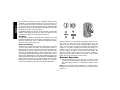
Using the Wireless Remote Control
The remote control allows one person to
operate and setup the laser from a distance.
The remote control features a speed/rotation
button, a scan mode button, and four arrows
pointing left, right, up, and down. The
speed/rotation and scan mode buttons operate
in exactly the same way as the speed/rotation
and scan mode buttons on the lasers control
panel. The arrow buttons operate differently
depending on whether the laser is set up in
plumb or level mode
In plumb (vertical) mode, the left and right buttons can be used to
rotate the plane of laser light left and right. The up and down
buttons operate only when the laser is in dot mode (0 rpm’s) or in
scan mode. When the laser is in dot mode, the up and down but-
tons are used to rotate the rotary head and therefore move the dot
up and down. When in scan mode, the up and down buttons move
the scan area up and down.
In level (horizontal) mode, the left and right buttons operate only
when the laser is in dot or scan mode. In dot mode the left and right
buttons rotate the rotary head and therefore move the dot left and
right. In scan mode the left and right buttons rotate the scan area
left and right. The up and down buttons operate the laser only when
in scan mode. The up button makes the scan area larger, and the
down button makes the scan area smaller.
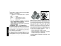
Digital Laser Detector: DW0772
Some laser kits unclude a DEWALT digital laser detector. The
D
EWALT digital laser detector allows you to locate a laser beam
emitted by a rotary laser in bright light conditions or over long dis-
tances. The detector can be used in both indoor and outdoor situ-
ations where it is difficult to see the laser beam. The detector is not
A
B
C
D
E
F
G
H

English
12
for use with non-rotating lasers but is compatible with most rotary
red-beam or infra-red (invisible) beam lasers on the market. It can
be set to indicate the location of the beam to either the nearest 1/8"
or the nearest 1/25". The detector gives both visual signals through
the display window (B) and audio signals through the speaker (E)
to indicate the location of the laser beam.
The D
EWALT digital laser detector can be used with or without the
detector clamp. When used with the clamp, the detector can be
positioned on a grade rod, leveling pole, stud or post.
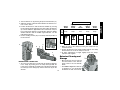
BATTERIES
The digital laser detector is powered by a 9 volt battery. To install
the battery provided, lift up on the battery compartment cover (F).
Place the 9 volt battery in the compartment, aligning the battery
as shown on the embossed icon (I).
DETECTOR CONTROLS
The detector is controlled by the power/volume button (C) and the
accuracy mode button (D). When the power/volume button is
pushed once, the detector is turned on. The top of the display win-
dow shows the on icon (J), and the volume icon (K). To decrease the
volume of the audible signal that the detector emits when it senses
a laser beam, push the button again; one of the half circles next to
the horn icon will dissappear. To turn off the audible signal push the
button a third time; the volume icon will dissapear. The D
EWALT dig-
ital laser detector also has an auto shut-off feature. If a rotary laser
beam does not strike the beam detection window, or, if no buttons
are pressed, the detector will shut itself off in about 30 minutes.
When the detector is on, the bottom of the window shows an accu-
racy mode icon. Either the ±1/25" accuracy mode icon (L) will
appear, or the ±1/8" accuracy mode icon (M) will appear. When the
±1/25" accuracy mode icon appears, it indicates that the detector
will give an “on grade” reading only when the laser beam is on
grade or no more than 1/25" above or below it. When the 1/8"
accuracy mode icon appears, it indicates that the detector will
give an “on grade” reading when the laser beam is on grade or
approximately 1/8" above or below it. Push the accuracy mode
button (D) once to change the accuracy mode.
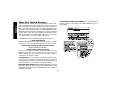
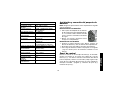
Detector Operation
1. Set up and position the rotary laser that you will be using
according to the manufacturer’s directions. Turn the laser on
and make sure that the laser is rotating and emitting a laser
beam.
NOTE: This detector has been designed to be used only with a
rotating laser. The detector will not work with a stationary beam
laser level.
F
J
K
L
M
I

English
13
2. Turn the detector on by pressing the power/volume button (C).
3. Adjust the volume as desired as described in the “detector con-
trols” section, above.
4. Position the detector so that the detector window (A) is facing
the laser beam produced by the rotary laser. Move the detector
up or down within the approximate area of the beam, until you
have centered the detector. For information about the display
window indicators and the audible signal indicators, see the
table titled “indicators”.
5. Use the marking notches (G) to accurately mark the position of
the laser beam.
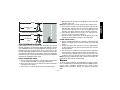
MOUNTING ON A GRADE ROD
1. To secure your detector to a grade rod, first attach the detector
to the clamp by pushing in on the clamp latch (N).Slide the
tracks on the clamp (O) around the rail on the detector (Q) until
the latch (R) on the clamp pops into the latch hole (R) on the
detector.
N
O
Q
R
S
R
2. Open the jaws of the clamp by turning the clamp knob (S)
counterclockwise.
3. Position the detector at the height needed and turn the clamp
knob clockwise to secure the clamp on the rod.
4. To make adjustments in height, slightly loosen the clamp,
reposition and retighten.
Detector Cleaning and
Storage
• Dirt and grease may be removed
from the exterior of the detector
using a cloth or soft, non-metallic
brush.
• The D
EWALT digital laser detector
is waterproof. If you should drop
the detector in mud, wet concrete,
Slightly Slightly
Above Above On Below Below
Grade Grade Grade Grade Grade
fast fast steady slow slow
beep beep tone beep beep
audible
signals
INDICATORS
display icons

English
14
or a similar substance, simply hose the detector off. do not use
high pressure water, e.g., from a pressure washer.
• The best storage place is one that is cool and dry—away from
direct sunlight and excess heat or cold.
Detector Service
Except for batteries, there are no user serviceable parts in the
Digital Laser Detector. Do not disassemble the unit. Unauthorized
tampering with the laser detector will void all warranties.
Detector Troubleshooting
THE DETECTOR WILL NOT TURN ON
• Press and release the power/volume button.
• Check to see that the battery is in place and in the proper
position.
• If the detector is very cold, allow it to warm up in a heated area.
• Replace the 9 volt battery. Turn the unit on.
• If the detector still does not turn on, take the detector to a
D
EWALT service center.
THE DETECTOR’S SPEAKER MAKES NO SOUND
• Ensure that the detector is on.
• Press the power/volume button. It will toggle from high, to low,
to mute.
• Ensure that the rotary laser is spinning and that it is emitting a
laser beam.
• If the detector is still not making any sound, take it to a D
EWALT
service center.
THE DETECTOR IS NOT RESPONDING TO MY STATIONARY
LASER LEVEL
• The D
EWALT Digital Laser Detector has been designed to work
only with rotary lasers.
THE DETECTOR IS GIVING OFF A TONE BUT THE LCD
DISPLAY WINDOW IS NOT FUNCTIONING.
• If the detector is very cold, allow it to warm up in a heated area.
• If the LCD display window is still not functioning, take the detec-
tor to a D
EWALT service center.
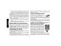
LASER MAINTENANCE
1. Under some conditions, the glass lens inside the rotary head
may collect some dirt or debris. This will affect beam quality and
operating range. the lens should be cleaned with a cotton swab
moistened with water as shown.
2. The flexible rubber shield can be cleaned with a wet lint-free
cloth such as a cotton cloth. USE WATER ONLY — DO NOT
use cleansers or solvents. Allow the unit to air dry before
storing.
3. To maintain the accuracy of your work, check the calibration of
the laser often. See the “Field Calibration Check” section of this
manual.
4. Calibration checks and other maintenance repairs can be per-
formed by D
EWALT service centers. Two free calibration
checks are included under the D
EWALT One Year Free Service
Contract.
5. When the laser is not in use, store it in the kit box provided.
6. Do not store your laser in the kit box if the laser is wet. Dry exte-
rior parts with a soft, dry cloth and allow the laser to air dry.
7. Do not store your laser at temperatures below 0˚F (-18˚C) or
above 105˚F (41˚C).
CLEANING
Exterior plastic parts may be cleaned with a damp cloth and mild
detergent. Although these parts are highly solvent resistant,
NEVER use solvents. Never use compressed air to clean the laser.

English
15
Field Calibration Check
Field calibration checks should be done frequently. This section
provides instructions for performing simple field calibration checks
of your D
EWALT Rotary Laser. Field calibration checks do not cali-
brate the laser. That is, these checks do not correct errors in the
leveling or plumbing capability of the laser. Instead, the checks indi-
cate whether or not the laser is providing a correct level and plumb
line. These checks cannot take the place of professional calibration
performed by a D
EWALT service center.
LEVEL CALIBRATION CHECK
1. Set up a tripod 50' (15m) from a vertical wall as shown. Make
sure the head of the tripod is level using a bubble level.
2. Mount your rotary laser on the tripod so that the X-axis points
toward the wall as shown.
3. Turn the laser on, but do not put the laser in rotation mode.
APPROX. 50 ft.
(15m)
APPROX. 50 ft.
(15m)
BEAM
BEAM
LASER UNIT ROTATED 180˚
4. Manually point the dot at the far wall. Mark the center of the dot
elevation on the wall.
NOTE: pointing the dot on a white surface makes marking easier.
5. Turn the entire unit 180˚ so that the X-axis points away from the
wall. Manually rotate the laser dot (or use the right /left arrows
on the remote control) so it is as close as possilbe to the first
elevation mark. Again, mark the center of the dot on the wall.
6. If the distance between the two marks is no more than 1/8"
(3.2 mm), the laser is properly calibrated.
7. Repeat the above steps for the Y-axis by pointing the Y-axis
towards the wall and then turning the laser 180˚ again.
PLUMB ERROR CHECK
1. Using a standard plumb bob as a reference, mark the top and
bottom of a wall (Be sure to mark the wall and not the floor and
ceiling.)
2. Position the rotary laser securely on the floor approximately
3' (1m) from the wall. The closer to the wall, the more accurate
this check will be.
3. Turn the laser on, and point the dot at the mark on the bottom
of the wall. Then, using the up/down arrows on the remote con-
trol, rotate the dot upwards. If the center of the dot scans over
the mark on the top of the wall, the laser is properly calibrated.
NOTE: This check should be done with a wall no shorter than the
tallest wall for which this laser will be used.
Repairs
To assure product SAFETY and RELIABILITY, repairs, mainte-
nance and adjustments should be performed by a D
EWALT factory
service center, a D
EWALT authorized service center or other
qualified service personnel. Always use identical replacement
parts.

English
16
Three Year Limited Warranty
DEWALT will repair, without charge, any defects due to faulty mate-
rials or workmanship for three years from the date of purchase.
This warranty does not cover part failure due to normal wear or tool
abuse. For further detail of warranty coverage and warranty repair
information, visit www.dewalt.com or call 1-800-4-D
EWALT (1-800-
433-9258). This warranty does not apply to accessories or damage
caused where repairs have been made or attempted by others.
This warranty gives you specific legal rights and you may have
other rights which vary in certain states or provinces.
In addition to the warranty, D
EWALT tools are covered by our:
1 YEAR FREE SERVICE
D
EWALT will maintain the tool and replace worn parts caused by
normal use, for free, any time during the first year after purchase.
2 YEARS FREE SERVICE ON
XRP
™ BATTERY PACKS
DC9096, DC9091 and DC9071
90 DAY MONEY BACK GUARANTEE
If you are not completely satisfied with the performance of your
D
EWALT Power Tool, Laser, or Nailer for any reason, you can
return it within 90 days from the date of purchase with a receipt for
a full refund – no questions asked.
LATIN AMERICA: This warranty does not apply to products sold in
Latin America. For products sold in Latin America, see country
specific warranty information contained either in the packaging, call
the local company or see website for warranty information.
RECONDITIONED PRODUCT: Reconditioned product is covered
under the 1 Year Free Service Warranty. The 90 Day Money Back
Guarantee and the Three Year Limited Warranty do not apply to
reconditioned product.
FREE WARNING LABEL REPLACEMENT: If your warning labels
become illegible or are missing, call 1-800-4-D
EWALT for a free
replacement.

Français
17
SI VOUS AVEZ DES QUESTIONS OU VOULEZ NOUS FAIRE
PART DE VOS COMMENTAIRES CONCERNANT CET OUTIL OU
TOUT AUTRE OUTIL D
EWALT, COMPOSEZ SANS FRAIS LE :
1 800 433-9258
AVERTISSEMENT : Lire, comprendre et suivre
toutes les directives précisées ci-dessous, y
compris les consignes de sécurité, afin d’éviter les
risques de choc électrique, d’incendie ou de blessure
grave.
CONSERVER CES DIRECTIVES
Consignes de sécurité concernant
les lasers
• Ne pas utiliser le laser dans une atmosphère explosive,
comme à proximité de liquides, de gaz ou de poussières
inflammables; le moteur peut créer des étincelles et enflammer
les vapeurs ou les poussières environnantes.
• N’utiliser le laser qu’avec les piles désignées, car l’utilisation
d’un autre type de piles pourrait entraîner un risque d’incendie.
• Lorsqu’on n’utilise pas le laser, le ranger hors de la portée
des enfants ou des personnes non qualifiées; les outils sont
dangereux entre les mains de personnes inexpérimentées.
• N’utiliser que les accessoires recommandés par le fabricant
pour le modèle concerné; un accessoire destiné à un laser par-
ticulier peut devenir dangereux lorsqu’il est utilisé avec un autre.
• L’outil doit être entretenu ou réparé par le personnel
qualifié seulement; toute maintenance effectuée par une
personne non qualifiée pourrait entraîner des risques de
blessure. Pour obtenir le numéro du centre de service
D
E
WALT le plus près, composer le 1 800 433-9258 ou consulter
le site Internet http://www.dewalt.com.
• Ne pas utiliser un dispositif optique, tel qu’un téléscope ou
une lunette de passage, pour examiner le faisceau laser afin
d’éviter de blesser grièvement les yeux.
• Ne pas mettre le laser dans une position qui pourrait
encourager une personne à regarder directement le fais-
ceau laser, volontairement ou involontairement, car cela pour-
rait blesser grièvement les yeux.
• Mettre le laser hors tension après chaque utilisation, car un
laser laissé sous tension encourage une personne à regarder
directement le faisceau laser.
• La réparation et l’entretien DOIVENT être effectués dans un
centre de service autorisé ou par du personnel qualifié;
toute opération d’entretien ou de réparation effectuée par une
personne non qualifiée pourrait entraîner des blessures graves.
• Ne pas démonter l’outil laser; ce dernier ne comprend aucune
pièce interne destinée à être entretenue par l’utilisateur.
• Ne pas utiliser le laser en présence d’un enfant, ni autoriser
les enfants à utiliser le laser afin d’éviter les blessures graves
aux yeux.
• Ne pas retirer ni abîmer les étiquettes d’avertissement; le
fait de retirer les étiquettes augmentera les risques d’exposition
aux rayonnements laser.
• S’assurer de bien déposer le laser sur une surface de
niveau afin de l’empêcher de tomber et de s’endommager ou
de blesser l’utilisateur.
• Porter des vêtements appropriés; ne pas porter de vête-
ments amples ni de bijoux. Couvrir ou attacher les cheveux
longs. Garder les cheveux, les vêtements, les bijoux et les
gants éloignés des pièces mobiles, car ceux-ci peuvent s’y
coincer. Se tenir éloigné des évents puisque ces derniers pour-
raient camoufler des pièces mobiles.

Français
18
MISE EN GARDE : L’utilisation de procédures, de com-
mandes ou de réglages autres que ceux précisés aux
présentes pourrait entraîner des risques d’exposition aux
rayonnements laser.
AVERTISSEMENT! NE PAS DÉMONTER LE LASER
ROTATIF. L’outil ne comprend aucune pièce interne destinée à
être entretenue par l’utilisateur. Le fait de démonter le laser
rotatif annulera toute garantie appuyant ce produit; on ne doit
jamais modifier ce dernier de quelque manière que ce soit afin
d’éviter d’entraîner des risques d’exposition aux rayonnements.
• L’étiquette apposée sur l’outil peut afficher les symboles suivants :
V ........................volts
MW ....................milliwatts
................symbole d’avertissement du laser
nm......................longueur d’onde exprimée en nanomètres
IIIa......................laser de classe IIIa
• Pour des fins pratiques et de sécurité, la scie à onglets com-
prend les étiquettes d’avertissement suivantes
ÉVITER L’EXPOSITION AUX RAYONNEMENTS LASER
ÉMIS PAR CES OUVERTURES.
DANGER. RAYONNEMENTS LASER. ÉVITER LES
RISQUES D’EXPOSITION OCULAIRE.
Information sur les lasers
Le laser rotatif sans fil DW077 est répertorié en tant que PRODUIT
À LASER DE CLASSE IIIa; il est conforme aux exigences perti-
nentes contenues au chapitre 21 du Code of Federal Regulations
(ou CFR) des États-Unis établies par les organismes américains
suivants : le Department of Health, Education and Welfare, le Food
and Drug Administration et le Center for Devices and Radiological
Health.
Ces dispositifs sont conformes aux dispositions de la partie 15 des
règlements de la FCC. Le fonctionnement doit respecter les deux
conditions suivantes : (1) ce dispositif ne doit pas causer de brouil-
lage nuisible, et (2) ce dispositif doit accepter tout brouillage qu’il
reçoit, y compris celui qui cause un fonctionnement indésirable.
REMARQUE : les essais ont démontré que cet appareil respecte
les limites régissant un dispositif numérique de classe B, confor-
mément aux dispositions de la partie 15 des règlements de la
FCC. Le but de ces limites est de fournir une protection
raisonnable contre le brouillage nuisible dans une installation rési-
dentielle. Cet appareil génère, utilise et peut produire une énergie
radiofréquence rayonnée et, lorsqu’il n’est pas installé et utilisé
conformément aux directives, peut causer le brouillage nuisible
des communications radio. Cependant, il n’existe aucune garantie
que le brouillage ne se produira pas dans une installation partic-
ulière. Si cet appareil entraîne le brouillage nuisible de la réception
radio ainsi que celle des programmes de télévision, ce qui peut
être déterminé en allumant et en éteignant l’appareil, on invite l’u-
tilisateur à tenter de corriger le problème relié au brouillage au
moyen de l’une des deux méthodes suivantes : en réorientant ou
en déplaçant l’antenne de réception, en augmentant l’espace
entre l’appareil et le récepteur ou en raccordant l’appareil à une
prise murale reliée à un circuit autre que celui dans lequel le
La page est en cours de chargement...
La page est en cours de chargement...
La page est en cours de chargement...
La page est en cours de chargement...
La page est en cours de chargement...
La page est en cours de chargement...
La page est en cours de chargement...
La page est en cours de chargement...
La page est en cours de chargement...
La page est en cours de chargement...
La page est en cours de chargement...
La page est en cours de chargement...
La page est en cours de chargement...
La page est en cours de chargement...
La page est en cours de chargement...
La page est en cours de chargement...
La page est en cours de chargement...
La page est en cours de chargement...
La page est en cours de chargement...
La page est en cours de chargement...
La page est en cours de chargement...
La page est en cours de chargement...
La page est en cours de chargement...
La page est en cours de chargement...
La page est en cours de chargement...
La page est en cours de chargement...
La page est en cours de chargement...
La page est en cours de chargement...
La page est en cours de chargement...
La page est en cours de chargement...
La page est en cours de chargement...
La page est en cours de chargement...
La page est en cours de chargement...
La page est en cours de chargement...
La page est en cours de chargement...
La page est en cours de chargement...
-
 1
1
-
 2
2
-
 3
3
-
 4
4
-
 5
5
-
 6
6
-
 7
7
-
 8
8
-
 9
9
-
 10
10
-
 11
11
-
 12
12
-
 13
13
-
 14
14
-
 15
15
-
 16
16
-
 17
17
-
 18
18
-
 19
19
-
 20
20
-
 21
21
-
 22
22
-
 23
23
-
 24
24
-
 25
25
-
 26
26
-
 27
27
-
 28
28
-
 29
29
-
 30
30
-
 31
31
-
 32
32
-
 33
33
-
 34
34
-
 35
35
-
 36
36
-
 37
37
-
 38
38
-
 39
39
-
 40
40
-
 41
41
-
 42
42
-
 43
43
-
 44
44
-
 45
45
-
 46
46
-
 47
47
-
 48
48
-
 49
49
-
 50
50
-
 51
51
-
 52
52
-
 53
53
-
 54
54
-
 55
55
-
 56
56


DeWalt DW077K Manuel utilisateur
- Taper
- Manuel utilisateur
dans d''autres langues
- English: DeWalt DW077K User manual
- español: DeWalt DW077K Manual de usuario
Documents connexes
-
DeWalt DW077 Manuel utilisateur
-
DeWalt DCE080D1GS Manuel utilisateur
-
-
DeWalt DW073 Manuel utilisateur
-
-
-
-
DeWalt DC9071 Manuel utilisateur
-
-