red lion DA 6UIN Module Manuel utilisateur
- Taper
- Manuel utilisateur

Installation DA6UIN-B
Drawing No. LP1122
Revised 03/2020
DA Series Universal Analog Input Module
With 6 Isolated Channels
Installation Guide
1
MODULE PACKAGE CHECKLIST
This product package should contain the items listed below. If
any items are missing or damaged, contact Red Lion immediately.
- DIN rail mount DA 6UIN Module
- Installation Guide
GENERAL DESCRIPTION
The DA 6UIN module is designed for use with the DA70
controllers, that can support up to 10 I/O modules simultaneously.
This module features 6 Universal Analog Inputs operating at
16-bit resolution, which makes it an ideal choice for a data-
acquisition application. The module can accept a wide range of
thermocouples and RTDs, as well as 0/4-20 mA and 0-10 V
Process signals. Each input has a dedicated alarm LED that
indicates a variety of conditions.
The modules connect and communicate via proprietary
backplane to the DA host device. The DA host device, equipped
with serial ports as well as Ethernet port(s), allows the system to
share data with PCs, PLCs, and SCADA systems.
Internal power management circuits allow the module to be
replaced while power is applied, which reduces downtime in the
event of a module failure. All configuration information is stored
locally within the module, as well as in the Host, so replacement
modules do not need to be configured.
CONFIGURATION
The DA 6UIN modules are configured with Windows
®
compatible Crimson
®
software. The software is an easy to use,
graphical interface which provides a means of configuration and
commissioning of new systems, as well as routine module
re-calibration.
ALARMS
There are a total of 6 red Alarm LEDs – one per Universal Input
channel. The 6UIN module Status LED shows general module
health status. Please reference the LED section for a list of LED
functions.
SAFETY SUMMARY
All safety related regulations, local codes and instructions that
appear in this document or on equipment must be observed to
ensure personal safety and to prevent damage to either the
device or equipment connected to it.
Do not use these products to replace proper safety interlocking.
No software-based device (or any other solid-state device) should
ever be designed to be responsible for the maintenance of
personnel safety or consequential equipment not equipped with
safeguards. Red Lion disclaims any responsibility for damages,
either direct or consequential, that result from the use of this
equipment in a manner not specified.
CAUTION: Risk of Danger
Read complete instructions prior to installation and
operation of the unit.
ATTENTION : Risque de danger
Lire les instructions complètes avant l’installation et
l’utilisation de l’appareil.
WARNING - EXPLOSION HAZARD - SUBSTITUTION
OF COMPONENTS MAY IMPAIR SUITABILITY FOR
CLASS I, DIVISION 2
AVERTISSEMENT - DANGER D’EXPLOSION - LE
REMPLACEMENT DE COMPOSANTS PEUT NUIRE À
L’APTITUDE À LA CLASSE I, DIVISION 2
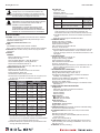
z Universal inputs accept TC, RTD, 0-5 V, 0-10 V, 0-20 mA,
4-20 mA, 0-50 mV signals
z Offers complete isolation; inputs, power and Controller
z Ideal for data acquisition applications
z Fully isolated design provides reliable operation
z Configured using Crimson
®
software (version 3.1 or later)
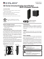
FOR USE IN HAZARDOUS LOCATIONS:
Class I, Division 2, Groups A, B, C, and D
T4
C
US
U
L
R
LISTED
IND.CONT. EQ.
E317425
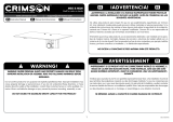
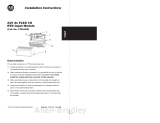
0.49
(12.51)
0.45 (11.50)
4.53 (114.97)
6.22
(157.91)
1.91
(48.51)
1.35
(34.32)
32
31
30
29
28
27
26
25
24
23
22
21
20
19
18
17
16
15
14
13
12
11
10
09
08
07
06
05
04
03
02
01
6.00
(152.40)
DIMENSIONS In inches (mm)
II 3 G Ex ec IIC T4 Gc
DEMKO 20 ATEX 2268X
IECEx UL 20.0007X

2
Drawing No. LP1122 Revised 03 2020
SPECIFICATIONS
1. POWER: Power is supplied by the DA host device. Modules
may be hot-swapped (replaced while powered up) in non-
hazardous locations only.
6UIN Port-Isolated Max Power: 1 W
2. LEDs:
STS: RGB Status LED shows module condition
AL1 - 6: Alarm LEDs are lit during an internal alarm condition
3. MEMORY: Non-volatile memory retains all programmable
parameters.
4. INPUTS:
GENERAL:
Effective Resolution: Full 16-bit
Sample Time: 50 msec
Common Mode Rejection: >110 dB, 50/60 Hz
Normal Mode Rejection: >50 dB, 50/60 Hz
Temperature Coefficient: 0.01%/
°
C
Step Response Time: 100 msec typ., 200 msec max
THERMOCOUPLE INPUTS:
Types: T, E, J, K, R, S, B, N, C
Slope & Offset: Provides sensor error correction
Input Impedance: 20 M ohm
Lead Resistance Effect: 0.25 µV/ohm
Cold Junction Compensation: Less than ±1 °C typical (±1.5
°C max) over -40 to 75 °C ambient temperature
Resolution: 0.1
°
TYPE
MEASUREMENT
RANGE
WIRE COLOR
ANSI BS 1843
T
-200 to +400 °C
-328 to +752 °F
(+) Blue
(-) Red
(+) White
(-) Blue
E
-200 to +730 °C
-328 to +1346 °F
(+) Violet
(-) Red
(+) Brown
(-) Blue
J
-200 to +760 °C
-328 to +1400 °F
(+) White
(-) Red
(+) Yellow
(-) Blue
K
-200 to +1350 °C
-328 to +2462 °F
(+) Yellow
(-) Red
(+) Brown
(-) Blue
R
0 to +1768 °C
+32 to +3214 °F
No Standard
(+) White
(-) Blue
S
0 to +1768 °C
+32 to +3214 °F
No Standard
(+) White
(-) Blue
B
+149 to +1820 °C
+300 to +3308 °F
No Standard No Standard
N
-200 to +1300 °C
-328 to +2372 °F
(+) Orange
(-) Red
(+) Orange
(-) Blue
C W5/W6
0 to +2315 °C
+32 to +4199 °F
No Standard No Standard
mV 0 mV to 50 mV N/A N/A
Temperature Indication Accuracy: ± (0.3% of span, +1 °C).
Includes NIST conformity, cold junction effect, A/D
conversion errors, temperature coefficient and linearization
conformity at 23 °C after 20 minute warm up.
Probe Break Response: Upscale drive, Input Fault Alarm bit
set high, ALM LED illuminates.
RTD INPUTS:
Type: 2 or 3 wire
Excitation: 150 µA
Lead Resistance: 15 ohms Max
Resolution: 1 or 0.1°
TYPE INPUT TYPE RANGE
385 100 ohm platinum, Alpha = 0.00385
-200 to +600 °C
-328 to +1100 °F
392 100 ohm platinum, Alpha = 0.003919
-200 to +600 °C
-328 to +1100 °F
672 120 ohm nickel, Alpha = 0.00672
-80 to +215 °C
-112 to +419 °F
Slope & Offset: Provides sensor error correction
Temperature Indication Accuracy: Includes NIST conformity,
A/D conversion errors, temperature coefficient and
linearization conformity at 23 °C after 20 minute warm up.
Probe Break Response: If channel is enabled: upscale drive,
Input
Fault Alarm bit set high, ALM LED illuminates
5. CURRENT INPUTS:
Ranges: 0-20 mA or 4-20 mA
Programmable Scaling: ±30,000
Input Impedance: 10 Ohm
Max. Continuous Overload: 100 mA
Accuracy: ±0.1% of span
Input Fault Response: Upscale Drive, Input Fault Alarm bit set
high, ALx LED illuminates below -2 mA, and above 22 mA
for 0-20 mA range; below +2 mA and above 22 mA for 4-20
mA signals.
6. VOLTAGE INPUTS:
Ranges: 0-10 VDC, 0-5 V, 0-50 mV
Programmable Scaling: ±30,000
Input Impedance: 1 M Ohm
Max. Continuous Overload: 50 V
Accuracy: ±0.1% of span
Input Fault Response: Upscale Drive, Input Fault Alarm bit set
high, ALx LED illuminates below -0.5 or -10.5 VDC and
above +10.5 VDC.
7. ENVIRONMENTAL CONDITIONS:
Operating Temperature Range: -40 to 75 °C
Storage Temperature Range: -40 to +85 °C
Operating and Storage Humidity: 0 to 85% max. Relative
humidity, non-condensing.
Vibration to IEC 60068-2-6: Operational 5-500 Hz, 2 g
Shock to IEC 68-2-27: Operational 15 g
Altitude: Up to 2000 meters
Installation Category II, Pollution Degree 2 as defined in IEC/
EN 60664-1.
8. CERTIFICATIONS AND COMPLIANCES:
CE Approved
EN 61326-1 Immunity to Industrial Locations
Emission CISPR 11 Class A
IEC/EN 61010-1
RoHS Compliant
ATEX Approved
II 3 G Ex ec IIC T4 Gc
DEMKO 20 ATEX 2268X
IECEx Approved
IECEx UL 20.0007X
UL Hazardous: File #E317425
Rugged IP30 enclosure
9. CONSTRUCTION: Polycarbonate enclosure with IP30 rating.
For use only in approved enclosure.
10. CONNECTIONS: Removable wire clamp screw terminal
blocks
Wire Strip Length: 0.3" (7.5 mm)
Wire Gauge Capacity: 14 to 24 AWG (2.08 to 0.20 mm
2
)
copper wire only
Torque: 2 inch-lbs (0.23 N-m)
11. MOUNTING: Mounts onto standard DIN style top hat (T)
profile mounting rails according to EN50022 – 35 x 7.5 mm
and 35 x 15 mm.
12. WEIGHT: 10.2 oz (317.26 g)
This equipment is suitable for use in Class I, Division 2,
Groups A, B, C, D, or non-hazardous locations only.
Cet équipement est adapté à une utilisation dans des
endroits de classe I, Division 2, Groupes A, B, C, D, ou
dans des endroits non dangereux seulement.
WARNING - EXPLOSION HAZARD. NOT HOT
SWAPPABLE. DO NOT REMOVE OR REPLACE WHILE
CIRCUIT IS LIVE UNLESS THE AREA IS FREE OF
IGNITIBLE CONCENTRATIONS.
AVERTISSEMENT - RISQUE D’EXPLOSION. NON
ÉCHANGEABLE À CHAUD. NE PAS RETIRER OU
REMPLACER SOUS TENSION SAUF SI LA ZONE EST
EXEMPTE DE CONCENTRATIONS INFLAMMABLES.

3
Revised 03 2020 Drawing No. LP1122
EMC INSTALLATION GUIDELINES
Although Red Lion Controls’ products are designed with a high
degree of immunity to Electromagnetic Interference (EMI), proper
installation and wiring methods must be followed to ensure
compatibility in each application. The type of the electrical noise,
source or coupling method into a unit may be different for various
installations. Cable length, routing, and shield termination are
very important and can mean the difference between a successful
or troublesome installation. Listed are some EMI guidelines for a
successful installation in an industrial environment.
1. A unit should be mounted in a metal enclosure, which is
properly connected to protective earth.
2. Use shielded cables for all Signal and Control inputs. The
shield connection should be made as short as possible. The
connection point for the shield depends somewhat upon the
application. Listed below are the recommended methods of
connecting the shield, in order of their effectiveness.
a. Connect the shield to earth ground (protective earth) at one
end where the unit is mounted.
b. Connect the shield to earth ground at both ends of the cable,
usually when the noise source frequency is over 1 MHz.
3. Never run Signal or Control cables in the same conduit or
raceway with AC power lines, conductors, feeding motors,
solenoids, SCR controls, and heaters, etc. The cables should
be run through metal conduit that is properly grounded. This
is especially useful in applications where cable runs are long
and portable two-way radios are used in close proximity or if
the installation is near a commercial radio transmitter. Also,
Signal or Control cables within an enclosure should be routed
as far away as possible from contactors, control relays,
transformers, and other noisy components.
4. Long cable runs are more susceptible to EMI pickup than
short cable runs.
5. In extremely high EMI environments, the use of external EMI
suppression devices such as Ferrite Suppression Cores for
signal and control cables is effective. The following EMI
suppression devices (or equivalent) are recommended:
Fair-Rite part number 0443167251 (Red Lion Controls
#FCOR0000)
Line Filters for input power cables:
Schaffner # FN2010-1/07 (Red Lion Controls #LFIL0000)
6. To protect relay contacts that control inductive loads and to
minimize radiated and conducted noise (EMI), some type of
contact protection network is normally installed across the
load, the contacts or both. The most effective location is
across the load.
a. Using a snubber, which is a resistor-capacitor (RC) network or
metal oxide varistor (MOV) across an AC inductive load is very
effective at reducing EMI and increasing relay contact life.
b. If a DC inductive load (such as a DC relay coil) is controlled
by a transistor switch, care must be taken not to exceed the
breakdown voltage of the transistor when the load is
switched. One of the most effective ways is to place a
diode across the inductive load. Most Red Lion products
with solid state outputs have internal zener diode
protection. However external diode protection at the load is
always a good design practice to limit EMI. Although the
use of a snubber or varistor could be used.
Red Lion part numbers: Snubber: SNUB0000
Varistor: ILS11500 or ILS23000
7. Care should be taken when connecting input and output
devices to the instrument. When a separate input and output
common is provided, they should not be mixed. Therefore a
sensor common should NOT be connected to an output
common. This would cause EMI on the sensitive input
common, which could affect the instrument’s operation.
Visit http://www.redlion.net/emi for more information on EMI
guidelines, Safety and CE issues as they relate to Red Lion
products.
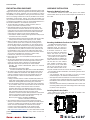
HARDWARE INSTALLATION
Removing Module From Cradle
To remove the module from the cradle, push in the module
release button at the top of the cradle and pull the module out of
the cradle.
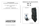
Attaching the Module/Cradle to the DIN Rail
The DIN rail should be mounted
horizontally so that the unit’s
ventilation holes are vertical in
relation to installation orientation.
A minimum clearance of 1 inch
(25.4 mm) should be maintained
above and below the unit to
ensure proper thermal regulation.
The cradle can be installed on
the DIN rail with or without the
module attached. Ensure the DIN
rail lock latch is in the outward
most position (unlocked). Hook
the top back of the cradle DIN
rail clip over the DIN rail. Press
the cradle until flush with the rail
and push the DIN rail lock latch to the latched (in) position.
For hazardous location installation, the following shall be taken
into consideration:
— The equipment shall only be used in an area of at least
pollution degree 2, as defined in EN/IEC 60664-1.
— The equipment shall be installed in an enclosure that provides
a minimum ingress protection of IP54 in accordance with EN/
IEC 60079-0. The enclosure shall be accessible only with the
use of a tool.
— Transient protection shall be provided that is set at a level not
exceeding 140% of the peak rated voltage value at the supply
terminals to the equipment.
Installing Module into Cradle
Push module into cradle until you hear an audible click
indicating it is properly latched.
32
31
30
29
28
27
26
25
24
23
22
21
20
19
18
17
16
15
14
13
12
11
10
09
08
07
06
05
04
03
02
01
MODULE
1
CRADLE
2
DIN RAIL LOCK LATCH
3
Unlock Lock
32
31
30
29
28
27
26
25
24
23
22
21
20
19
18
17
16
15
14
13
12
11
10
09
08
07
06
05
04
03
02
01
MODULE CRADLE
4
DIN
rail

4
Drawing No. LP1122 Revised 03 2020
MODULE HOT SWAPPING
If the area is known to be non-hazardous (free of ignitable
concentrations), then a module can be removed and/or installed
into a cradle attached to the controller while power is applied.
However, it is NOT recommended to connect to or remove from
the controller, a module/cradle pair or group of modules/cradles,
while power is applied. The power should be turned off anytime
a cradle or group of cradles (with or without modules) is plugged
into or removed from the controller.
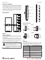
BLOCK DIAGRAM
A
POWER
SUPPLY
+
-
VDC
DA SERIES HOST
DA 6UIN MODULE
E
ISOLATED
POWER
SUPPLY
INPUT 4
F
ISOLATED
INPUT 5
G
ISOLATED
INPUT 6
D
ISOLATED
INPUT 3
C
ISOLATED
INPUT 2
B
ISOLATED
INPUT 1
WIRING
WIRING CONNECTIONS
All power and input wiring must be in accordance with Class I,
Division 2 wiring methods and in accordance with the authority
having jurisdiction.
All conductors should meet voltage and current ratings for each
terminal. When wiring the module, use the numbers on the label
to identify the position number with the proper function. Strip
the wire, leaving approximately 0.3" (7.5 mm) of bare wire
exposed. Insert the wire into the terminal, and tighten.
INPUT CONNECTIONS
THERMOCOUPLE VOLTAGE
RTD CURRENT
LEDs
STATUS LED
The red/green/blue Status LED is located at the top of the
module and provides information regarding the state of the
module. This includes indication of the various stages of the start-
up routine (power-up), as well as any errors that may occur.
LED COLOR(S) MEANING
Flashing Blue Module is booting.
Flashing Green Module is switching to configuration.
Green Module is performing normally.
Flashing Green/Purple Module is performing auto calibration.
Flashing Blue/Yellow Module is being flash upgraded by Crimson.
Flashing Red Error: general error with module.
Flashing Red/Green Error: module is controlling properly, but has lost
communication with the Host.
Flashing Yellow Error: no bus frequency /module is not enumerated
Flashing Red/Green/Blue Error: module is running the Factory Programming
Console.
CAUTION: Only UL listed wiring with temperature
ratings greater than 90 °C permitted for Class I, Division
2, Zone 2 and ATEX/IECex installations.
ATTENTION: Seul le câblage homologué UL avec des
températures nominales supérieures à 90°C est autorisé
pour les installations de classe I, Division 2 , zone 2 et
ATEX/IECex.
Terminals 17 to 24
Terminals 25 to 32
Terminals 9 to 16
Terminals 1 to 8
0-10V
4-20 mA
INPUT COM
TC/RTD+
RTD +EXC
01
02
03
06
04
05
08
07
14
09
11
10
13
12
16
15
20
17
19
18
21
22
24
23
29
28
26
25
27
32
31
30
N/C
N/C
6
5
4
2
1
3
0-10V
4-20 mA
INPUT COM
TC/RTD+
RTD +EXC
0-10V
4-20 mA
INPUT COM
TC/RTD+
RTD +EXC
0-10V
4-20 mA
INPUT COM
TC/RTD+
RTD +EXC
0-10V
4-20 mA
INPUT COM
TC/RTD+
RTD +EXC
0-10V
4-20 mA
INPUT COM
TC/RTD+
RTD +EXC
ISOLATEDISOLATEDISOLATEDISOLATEDISOLATEDISOLATED
0-10V
4-20 mA
INPUT COM
TC/RTD+
RTD +EXC
+
0-10V
4-20 mA
INPUT COM
TC/RTD+
RTD +EXC
VDC-
VDC+
0-10V
4-20 mA
INPUT COM
TC/RTD+
RTD +EXC
LOAD
POWER
+
+
_
0-10V
4-20 mA
INPUT COM
TC/RTD+
RTD +EXC

5
Revised 03 2020 Drawing No. LP1122
AL1 : AL6 – Alarm LEDs
The red Alarm LEDs indicate the presence of an alarm.
Whenever one of the alarms is active, the LED turns on.
FIRMWARE UPGRADE
The module’s firmware is stored in flash memory so that
software/ hardware conflicts are avoided, and so features can be
added in the future.
During a download, Crimson compares its own library of
firmware files with those stored in the module. If they do not
match, Crimson will download the necessary firmware.
RED LION CONTROLS TECHNICAL SUPPORT
If for any reason you have trouble operating, connecting, or
simply have questions concerning your new DA Module, contact
Red Lion’s technical support.
Support: support.redlion.net
Website: www.redlion.net
Inside US: +1 (877) 432-9908
Outside US: +1 (717) 767-6511
Red Lion Controls, Inc.
20 Willow Springs Circle York, PA 17406
ORDERING INFORMATION
DESCRIPTION PART NUMBER
DA 6 Universal Isolated Input Module DA M00I0 UIN6I 0000
Spaces in listed part numbers are shown to improve readability,
do not include when searching for or ordering these parts.
A listing of the entire DA Series family of products and accessories
can be found at www.redlion.net.

6
Drawing No. LP1122 Revised 03 2020
This page intentionally left blank.

7
Revised 03 2020 Drawing No. LP1122
This page intentionally left blank.

8
LIMITED WARRANTY
(a) Red Lion Controls Inc. (the “Company”) warrants that all Products shall be free from defects in material and
workmanship under normal use for the period of me provided in “Statement of Warranty Periods” (available at
www.redlion.net) current at the me of shipment of the Products (the “Warranty Period”). EXCEPT FOR THE
ABOVE-STATED WARRANTY, COMPANY MAKES NO WARRANTY WHATSOEVER WITH RESPECT TO THE
PRODUCTS, INCLUDING ANY (A) WARRANTY OF MERCHANTABILITY; (B) WARRANTY OF FITNESS FOR
A PARTICULAR PURPOSE; OR (C) WARRANTY AGAINST INFRINGEMENT OF INTELLECTUAL PROPERTY
RIGHTS OF A THIRD PARTY; WHETHER EXPRESS OR IMPLIED BY LAW, COURSE OF DEALING, COURSE
OF PERFORMANCE, USAGE OF TRADE OR OTHERWISE. Customer shall be responsible for determining that a
Product is suitable for Customer’s use and that such use complies with any applicable local, state or federal law.
(b) The Company shall not be liable for a breach of the warranty set forth in paragraph (a) if (i) the defect is a
result of Customer’s failure to store, install, commission or maintain the Product according to specicaons; (ii)
Customer alters or repairs such Product without the prior wrien consent of Company.
(c) Subject to paragraph (b), with respect to any such Product during the Warranty Period, Company shall, in its
sole discreon, either (i) repair or replace the Product; or (ii) credit or refund the price of Product provided that,
if Company so requests, Customer shall, at Company’s expense, return such Product to Company.
(d) THE REMEDIES SET FORTH IN PARAGRAPH (c) SHALL BE THE CUSTOMER’S SOLE AND EXCLUSIVE
REMEDY AND COMPANY’S ENTIRE LIABILITY FOR ANY BREACH OF THE LIMITED WARRANTY SET
FORTH IN PARAGRAPH (a).
COPYRIGHT
©2020 Red Lion Controls, Inc. All rights reserved. Red Lion and the Red Lion logo are trademarks of Red Lion Controls, Inc. All other
company and product names are trademarks of their respective owners.
-
 1
1
-
 2
2
-
 3
3
-
 4
4
-
 5
5
-
 6
6
-
 7
7
-
 8
8


red lion DA 6UIN Module Manuel utilisateur
- Taper
- Manuel utilisateur
dans d''autres langues
- English: red lion DA 6UIN Module User manual
Documents connexes
-
red lion DA 8AO Module Manuel utilisateur
-
-
-
-
red lion DA 8DI/8DO Module Manuel utilisateur
-
-
red lion E3 Guide de démarrage rapide
-
-
-
Autres documents
-
Spectrum Controls 1756sc-IC32 Quick Start
-
 Crimson AV M631 Guide d'installation
-
Crimson VW4600 Manuel utilisateur
-
Dwyer Series TTE Manuel utilisateur
-
PR 2204V104-UK Manuel utilisateur
-
 Allen-Bradley FLEX I/O 1794-IR8 Installation Instructions Manual
-
Christie Crimson HD31 Manuel utilisateur
-
 ARDETEM TPIs 2A User Handbook Manual


