
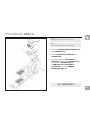
ELLIPTICAL OWNER’S MANUAL
MANUEL DU PROPRIÉTAIRE DE L’EXERCISEUR ELLIPTIQUE
MANUAL DEL PROPIETARIO DE LA MÁQUINA ELÍPTICA
Read the ELLIPTICAL GUIDE before using this OWNER’S MANUAL.
Lire le GUIDE D’UTILISATION DE L’EXERCISEUR ELLIPTIQUE avant de se servir du présent MANUEL DU PROPRIÉTAIRE.
Lea la GUÍA DEL USUARIO DE LA MÁQUINA ELÍPTICA antes de usar este MANUAL DEL PROPIETARIO.

2
3 ENGLISH
26 FRANÇAIS
50 ESPAÑOL

3
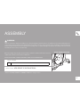
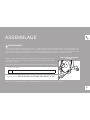
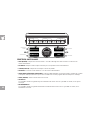
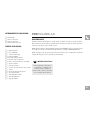
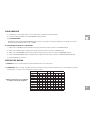
ASSEMBLY
There are several areas during the assembly process that special attention must be paid. It is very important to follow the assembly instructions
correctly and to make sure all parts are firmly tightened. If the assembly instructions are not followed correctly, the elliptical could have frame parts
that are not tightened and will seem loose and may cause irritating noises. To prevent damage to the elliptical, the assembly instructions must be
reviewed and corrective actions should be taken.
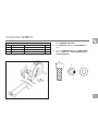
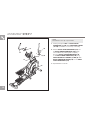
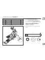
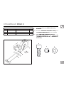
Before proceeding, find your elliptical’s serial number located on a white barcode sticker on the front
stabilizer tube and enter it in the space provided below.
ENTER YOUR SERIAL NUMBER AND MODEL NAME IN THE BOXES BELOW:
» Refer to the SERIAL NUMBER and MODEL NAME when calling for service.
WARNING
SERIAL NUMBER:
EP
SERIAL NUMBER LOCATION
MODEL NAME: AFG SPORT 5.7AE ELLIPTICAL

4
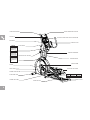
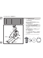
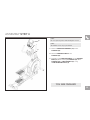
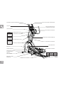
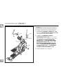
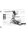
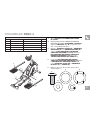
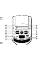
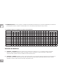
PIVOTING FOOT PADS
CRANK
TOP CAP
GUIDE RAIL SET
SPEAKERS
WATER BOTTLE HOLDER
UPPER HANDLEBAR
PULSE GRIPS
CONSOLE
STABILIZER TUBE
POWER CORD SOCKET
MAIN FRAME
PEDAL ARM
REAR COVER
TABLET/MAGAZINE POCKET
CONSOLE FAN
CONSOLE MAST
CONTROL KNOB AND DISPLAY WINDOWS
LOWER HANDLEBAR
LOWER LINK ARM
WARNING
CONSULT A PHYSICIAN PRIOR TO USING
ANY EXERCISE EQUIPMENT. POSSIBILITY
OF SERIOUS INJURY IF EQUIPMENT IS
USED IMPROPERLY. READ INSTRUCTION
MANUAL BEFORE USING. KEEP CHILDREN
OFF AND AWAY FROM THIS EQUIPMENT.
FOR CONSUMER USE ONLY.
AVERTISSEMENT
CONSULTEZ UN MÉDECIN AVANT
D’UTILISER CET ÉQUIPEMENT. POSSIBILITÉ
DE BLESSURES SÉRIEUSES SI
L’ÉQUIPEMENT EST UTILISE DE MANIÈRE
INCORRECTE. AVANT USAGE, LISEZ LE
GUIDE D’UTILISATEUR. NE LAISSEZ PAS CET
ÉQUIPEMENT À LA PORTÉE DES ENFANTS.
POUR USAGE DOMESTIQUE UNIQUEMENT.
PRECAUCIÓN
CONSULTAR CON UN MEDICO ANTES DE USAR
ESTE EQUIPO. POSIBILIDAD DE RESULTAR EN
HERIDAS GRAVES SI EL EQUIPO ESTÁ
UTILIZADO IMPROPIAMENTE. LEER LA GUÍA DE
INSTRUCCIONES ANTES DE USAR.MANTENER
NIÑOS PEQUEÑOS ALEJADOS DE LA MÁQUINA.
ESTE EQUIPO ES SÓLO PARA EL USO DEL
CONSUMIDOR.
CAUTION AVERTISSEMENT PRECAUCIÓN
KEEP HANDS AND
FEET AWAY FROM
THIS AREA.
GARDEZ LES MAINS ET LES
PIEDS LOIN DE CETTE
RÉGION.
MANTENGA LAS MANOS Y
LOS PIES LEJOS DE ESTA
AREA.

5
TOOLS INCLUDED:
F Screwdriver
F 5 mm L-Wrench
F 8 mm L-Wrench
F 13/17 mm Flat Wrench
PARTS INCLUDED:
F 1 Main Frame
F 1 Stabilizer Tube
F 1 Guide Rail Set
F 2 Pedal Arms
F 2 Lower Handlebars
F 2 Upper Handlebars
F 2 Lower Link Arms With Footpads
F 1 Top Cap
F 1 Console Mast
F 1 Console Mast Boot
F 1 Console
F 2 Handlebar Caps
F 1 Water Bottle Holder
F 1 Audio Adapter Cable
F 1 Power Cord
F 1 Hardware Kit
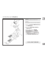
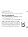
UNPACKING
Unpack the product where you will be using it. Place the elliptical carton on a level flat surface. It
is recommended that you place a protective covering on your floor. Never open box when it is on
its side.
NOTE: During each assembly step, ensure that ALL nuts and bolts are in place and partially
threaded in before completely tightening any ONE bolt.
NOTE: A light application of grease may aid in the installation of hardware. Any grease, such as
lithium bike grease is recommended.
If you have questions or if there
are any missing parts, contact
Customer Tech Support. Contact
information is located on the back
panel of this manual.
NEED HELP?
PRE ASSEMBLY

6
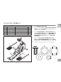
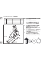
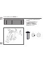
ASSEMBLY STEP 1
A
1
2
A
A Open HARDWARE FOR STEP 1.
B Attach the STABILIZER TUBE (1) to the MAIN FRAME
(2) using 2 BOLTS (A), 2 SPRING WASHERS (B) and 2
ARC WASHERS (C) on each side.
B
C
HARDWARE FOR STEP 1
PART TYPE DESCRIPTION QTY
M8X1.25PX30L 4A BOLT
8.2X15.4X2T 4B SPRING WASHER
8.4X17X1T 4C ARC WASHER
B
C
A
B
C
A
B
C
A
B
C

7
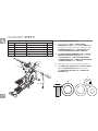
ASSEMBLY STEP 2
HARDWARE FOR STEP 2
PART TYPE DESCRIPTION QTY
M10X1.5PLX20L 4D BOLT
10.2X18.4X2.5T 4E SPRING WASHER
10.2X20X1.5T 4F FLAT WASHER
A Open HARDWARE FOR STEP 2.
B Align GUIDE RAIL SET (3) with MAIN FRAME (2) as
shown.
C Attach the GUIDE RAIL SET (3) to the MAIN FRAME
(2) using 4 BOLTS (D), 4 SPRING WASHERS (E) and
4 FLAT WASHERS (F).
D
3
2
E
F
D
E
F
D
E
F
D
E
F
D
E
F

8
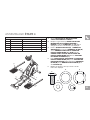
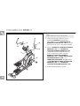
ASSEMBLY STEP 3
A Open HARDWARE FOR STEP 3.
B Remove PRE-INSTALLED BOLTS AND WASHERS (4)
from MAIN FRAME (2).
C Carefully pull the CONSOLE CABLE (5) through the
CONSOLE MAST (6) using the twist tie located inside
sthe CONSOLE MAST (6).
D Attach CONSOLE MAST (6) to MAIN FRAME (2) using
PRE-INSTALLED BOLTS AND WASHERS (4). Carefully
identify the LEFT and RIGHT PEDAL ARM by the “L” &
“R” SYMBOLS and arrange them on the appropriate side
of the elliptical.
E Slide WAVY WASHER (J) over CRANK (7) followed by
RIGHT PEDAL ARM (8R) as shown. Rest pedal arm
wheel on GUIDE RAIL (9).
F Attach the RIGHT PEDAL ARM (8R) to the CRANK (7)
using 1FLAT WASHER (I), 1SPRING WASHER (H)
and 1 BOLT(G).
G Repeat steps E–F on the opposite side of the elliptical.
J
2
4
5
6
7
8R
I
H
G
HARDWARE FOR STEP 3
PART TYPE DESCRIPTION QTY
M8X1.25PX20L 2G BOLT
8.2X15.4X2T 2H SPRING WASHER
8.2X20X1.5T 2I FLAT WASHER
17.2X22.5X0.5T 2J WAVY WASHER
G
H
I
J
9
Left Pedal
Arm Wheel
Right Pedal
Arm Wheel
8L
9
G
H
I
J

9
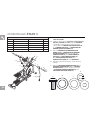
ASSEMBLY STEP 4
A
Open HARDWARE FOR STEP 4.
B Carefully identify the LEFT and RIGHT PEDAL LOWER LINK
ARM by the “L” & “R” SYMBOLS and arrange them on the
appropriate side of the elliptical.
C
Slide 1 FLAT WASHER (N), 1WAVY WASHER(0) and
another FLAT WASHER(N) onto the LOWER LINK ARM
PIVOT SHAFTS (10 L & R). Slide the LEFT LOWER
LINK ARM PIVOT SHAFT (10L) into the PEDAL ARM
BRACKET (11).
D
Attach the LEFT LOWER LINK ARM PIVOT SHAFT
(10L) to the PEDAL ARM BRACKET (11) using 1FLAT
WASHER (M), 1SPRING WASHER(L) and 1 BOLT(K).
E
Repeat steps C–D on the opposite side of the elliptical.
HARDWARE FOR STEP 4
PART TYPE DESCRIPTION QTY
M8X1.25PX20L 2K BOLT
8.2X15.4X2T 2L SPRING WASHER
8.2X20X1.5T 2M FLAT WASHER
10R
M
L
K
11
11
N
O
N
N
O
N
K
L
m
20.2X27.2X1.5T 4N FLAT WASHER
20.7X29.1X0.5T 2O WAVY WASHER
K
N
O
L
M
10L

10
ASSEMBLY STEP 5
A Open HARDWARE FOR STEP 5.
B Carefully identify the LEFT and RIGHT LOWER
HANDLEBAR (13 L&R) by the “L” & “R” SYMBOLS and
arrange them on the appropriate side of the elliptical. Slide 1
RUBBER WASHER (Q) and 1 FLAT WASHER (T) onto
the RIGHT CONSOLE MAST PIVOT SHAFT (12).
C Slide RIGHT LOWER HANDLEBAR (13R) onto RIGHT
CONSOLE MAST PIVOT SHAFT (12) and attach using
1FLAT WASHER (T), 1SMALL FLAT WASHER (R),
1HANDLEBAR CAP (14), 1SMALL FLAT WASHER(R)
1SPRING WASHER(S) and 1 BOLT(P).
D Repeat steps B–C on the opposite side of the elliptical.
E Slide FRONT TOP CAP PIECE (22) and MAST SLEEVE
(23) over CONSOLE MAST (24) and snap into place.
Snap REAR TOP CAP PIECE (25) into FRONT TOP
CAP PIECE (22).
12
T
Q
T
R
14
R
P
S
13R
13L
Q
T
T
14
R
R
P
S
HARDWARE FOR STEP 5
PART TYPE DESCRIPTION QTY
M8X1.25PX20L 2P BOLT
16.2X26.2X11.5T 2Q RUBBER WASHER
8.6X26X2.0T 4R
FLAT WASHER
8.2X15.4X2T 2 S SPRING WASHER
16X25X1.5T 4T FLAT WASHER
Q
T
P
R
S
23
22
24
25

11
ASSEMBLY STEP 6
A Open HARDWARE FOR STEP 6.
B Slide LOWER LINK ARM (15) into bottom end of LOWER
HANDLEBAR (16).
C Secure the joint with 1 BOLT (U), 1 SPRING WASHER
(V),1 FLAT WASHER (W) and 1 NUT (X).
D Repeat steps B–C on the opposite side of
the elliptical.
15
16
V
X
W
U
HARDWARE FOR STEP 6
PART TYPE DESCRIPTION QTY
M8X1.25PX70L-12L 2U BOLT
8.2X15.4X2T 2V SPRING WASHER
8.2X20X1.5T 2W FLAT WASHER
M8X1.25P 2X NUT
X
W
V
U

12
ASSEMBLY STEP 7
A Carefully arrange the LEFT and RIGHT UPPER
HANDLEBAR (17 L&R). Slide HANDLEBAR COVERS
(19 L&R) up handlebars out of the way of assembly.
B Slide the RIGHT UPPER HANDLEBAR (17R) onto
the RIGHT LOWER HANDLEBAR (18R) making
sure handlebars are joined together completely.
Secure the RIGHT UPPER HANDLEBAR (17R)
to the RIGHT LOWER HANDLEBAR (18R) using
PRE-ATTACHED SET SCREWS (Y) AND (Z). Slide
RIGHT HANDLEBAR COVER (19R) over the RIGHT
UPPER HANDLEBAR (17R)
C Repeat STEP B on left side.
17R
Y
Y
Z
18R
19R
18L
19L
17L
NOTE:
All hardware for this step is pre-installed.

13
YOU ARE FINISHED!
ASSEMBLY STEP 8
NOTE:
All hardware for this step is pre-installed.
A Remove 4 PRE-INSTALLED BOLTS (19) from the
CONSOLE (20).
B Attach the CONSOLE CABLES to the
CONSOLE (20).
C Carefully tuck the CONSOLE CABLES into the CONSOLE
MAST (21) before attaching the CONSOLE (20). Attach
CONSOLE (20) to CONSOLE MAST (21) using
4PRE-INSTALLED BOLTS (19).
20
19
21
NOTE:
Do not to pinch any wires while attaching the console.

14

15
ELLIPTICAL OPERATION
This section explains how to use your elliptical’s console and programming.
The BASIC OPERATION section in the ELLIPTICAL GUIDE has instructions for the following:
• LOCATION OF THE ELLIPTICAL
• POWER/GROUNDING INSRUCTIONS
• FOOT POSITIONING
• MOVING THE ELLIPTICAL
• LEVELING THE ELLIPTICAL
• POWER/MANUAL INCLINE OPERATION
• USING THE HEART RATE FUNCTION

16
G
H
D
E
N
C
B
O
P
F
K
L
A
I
G
J
H
M

17
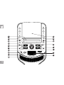
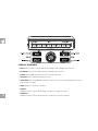
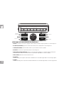
CONSOLE OPERATION
Note: There is a thin protective sheet of clear plastic on the overlay of the console that should be removed before use.
A) LED DISPLAY WINDOWS: time, distance, calories, heart rate, speed, and incline.
B) TARGET LED INDICATORS: indicate what target (if any) is set for the current program.
C) WORKOUT LED INDICATORS: indicate what workout is set for the current program.
D) SELECT TARGET/WORKOUT KNOB: rotate/press to select your desired workout/target
E) START: press to begin exercising, start your workout, or resume exercising after pause.
F) STOP: press to pause/end your workout. Hold for 3 seconds to reset the console.
G) RESISTANCE / KEYS: used to adjust resistance.
H) RESISTANCE QUICK KEYS: used to reach desired resistance more quickly.
I) FAN KEY: press to turn fan on and off.
J) FAN: personal workout fan.
K) SPEAKERS: music plays through speakers when your CD / MP3 player is connected to the console.
L) AUDIO IN JACK: plug your CD / MP3 player into the console using the included audio adaptor cable.
M) AUDIO OUT / HEADPHONE JACK: plug your headphones into this jack to listen to your music through the headphones. Note: when
headphones are plugged into the headphone jack the sound will no longer come out through the speakers.
N) USB INPUT: 1A/5V USB output power.
O) TABLET/READING RACK: holds tablet or reading material.
P) CHANGE DISPLAY: changes display level between top and bottom row.

18
DISPLAY WINDOWS
• TIME: Shown as minutes : seconds. View the time remaining or the time elapsed in your workout.
• DISTANCE: Shown as miles. Indicates distance traveled during your workout.
• SPEED: Shown as MPH. Indicates how fast the foot pedals are moving.
• CALORIES: Total calories burned during your workout.
• HEART RATE: Shown as BPM (beats per minute). Used to monitor your heart rate (displayed when contact is
made with both pulse grips).
• LEVEL: Shows the current level of resistance.
• TARGETS:
LED lights up next to currently selected target. If no LED is lit, no target is activated.
• WORKOUTS:
LED lights up next to currently selected workout. If no LED is lit, no workout is activated.

19
WORKOUT PROFILES
1) MANUAL: Adjust your resistance manually during your workout.
2) INTERVALS: Improves your strength, speed and endurance by increasing and decreasing the resistance throughout your workout to involve your
heart and other muscles. Includes 10 levels.
Resistance changes and segments
repeat 30 seconds and 90 seconds.
GETTING STARTED
1) Check to make sure no objects are nearby that will hinder the movement of the elliptical.
2) Plug in the power cord to turn the elliptical ON.
3) A) QUICK START UP
Simply press the START key to begin working out. The time will count up from 0:00, the resistance level will default to level 1. OR...
B) SELECT A TARGET AND WORKOUT
1) Select your USER by turning the workout knob and then pressing when your desired USER is displayed.
2) Select your WEIGHT by turning the workout knob and then pressing when your desired WEIGHT is displayed.
3) Select your PROGRAM by turning the workout knob and then pressing when your desired PROGRAM is displayed.
4) Adjust the SETTING by turning the workout knob and then pressing when your desired SETTING is displayed.
5) Press START to begin.
Segment Warm Up 1 2 Cool Down
TIme 60 60 60 60 30 90 60 60 60 60
Level 1 1 1 1 1 3 1 1 1 1 1
Level 2 1 1 1 2 4 1 2 1 1 1
Level 3 1 1 1 2 5 2 2 1 1 1
Level 4 1 1 1 3 5 3 3 1 1 1
Level 5 1 2 3 3 6 3 3 3 2 1
Level 6 1 2 3 4 7 4 4 3 2 1
Level 7 1 2 3 4 7 5 4 3 2 1
Level 8 1 2 3 5 8 5 5 3 2 1
Level 9 2 2 3 5 9 6 5 3 2 2
Level 10 2 2 4 6 10 6 6 4 2 2

20
TARGET PROFILES
1) TARGET 1 – DISTANCE: Push yourself and go further during your workout with 13 distance workouts. Choose from 1 mile, 2 miles, 5k,
5 miles, 10k, 8 miles, 15k, 10 miles, 20k, half marathon, 15 miles, 20 miles and marathon goals. User sets starting resistance levels.
2) TARGET 2 – CALORIES: Set goals for burning calories with nine workouts. Choose from 100, 200, 300, 400, 500, 600, 700, 800, or
900 calorie burn workouts. User sets starting resistance levels. Calories burned are calculated using weight input of user profile.
3) WEIGHT LOSS: A workout designed specifically to target fat. Promotes weight loss by increasing and decreasing the resistance, while keeping
you in your fat burning zone. Includes 10 levels
Resistance changes, segments repeat every 60 seconds.
Segment Warm Up 1 2 3 4 5 6 7 8 9 10 11 12 Cool Down
Time 60 60 60 60 60 60 60 60 60 60 60 60 60 60 60 60 60 60 60 60
Level 1 1 1 1 1 2 2 2 2 3 3 3 3 2 2 2 2 1 1 1 1
Level 2 1 1 1 2 2 2 3 3 3 3 3 3 3 3 2 2 2 1 1 1
Level 3 1 1 1 2 3 3 3 3 4 4 4 4 3 3 3 3 2 1 1 1
Level 4 1 1 1 3 3 3 4 4 4 4 4 4 4 4 3 3 3 1 1 1
Level 5 1 2 3 3 4 4 4 4 5 5 5 5 4 4 4 4 3 3 2 1
Level 6 1 2 3 4 4 4 5 5 5 5 5 5 5 5 4 4 4 3 2 1
Level 7 1 2 3 4 5 5 5 5 6 6 6 6 5 5 5 5 4 3 2 1
Level 8 1 2 3 5 5 5 6 6 6 6 6 6 6 6 5 5 5 3 2 1
Level 9 2 2 3 5 6 6 6 6 7 7 7 7 6 6 6 6 5 3 2 2
Level 10 2 2 4 6 6 6 7 7 7 7 7 7 7 7 6 6 6 4 2 2
La page est en cours de chargement...
La page est en cours de chargement...
La page est en cours de chargement...
La page est en cours de chargement...
La page est en cours de chargement...
La page est en cours de chargement...
La page est en cours de chargement...
La page est en cours de chargement...
La page est en cours de chargement...
La page est en cours de chargement...
La page est en cours de chargement...
La page est en cours de chargement...
La page est en cours de chargement...
La page est en cours de chargement...
La page est en cours de chargement...
La page est en cours de chargement...
La page est en cours de chargement...
La page est en cours de chargement...
La page est en cours de chargement...
La page est en cours de chargement...
La page est en cours de chargement...
La page est en cours de chargement...
La page est en cours de chargement...
La page est en cours de chargement...
La page est en cours de chargement...
La page est en cours de chargement...
La page est en cours de chargement...
La page est en cours de chargement...
La page est en cours de chargement...
La page est en cours de chargement...
La page est en cours de chargement...
La page est en cours de chargement...
La page est en cours de chargement...
La page est en cours de chargement...
La page est en cours de chargement...
La page est en cours de chargement...
La page est en cours de chargement...
La page est en cours de chargement...
La page est en cours de chargement...
La page est en cours de chargement...
La page est en cours de chargement...
La page est en cours de chargement...
La page est en cours de chargement...
La page est en cours de chargement...
La page est en cours de chargement...
La page est en cours de chargement...
La page est en cours de chargement...
La page est en cours de chargement...
La page est en cours de chargement...
La page est en cours de chargement...
La page est en cours de chargement...
La page est en cours de chargement...
La page est en cours de chargement...
La page est en cours de chargement...
-
 1
1
-
 2
2
-
 3
3
-
 4
4
-
 5
5
-
 6
6
-
 7
7
-
 8
8
-
 9
9
-
 10
10
-
 11
11
-
 12
12
-
 13
13
-
 14
14
-
 15
15
-
 16
16
-
 17
17
-
 18
18
-
 19
19
-
 20
20
-
 21
21
-
 22
22
-
 23
23
-
 24
24
-
 25
25
-
 26
26
-
 27
27
-
 28
28
-
 29
29
-
 30
30
-
 31
31
-
 32
32
-
 33
33
-
 34
34
-
 35
35
-
 36
36
-
 37
37
-
 38
38
-
 39
39
-
 40
40
-
 41
41
-
 42
42
-
 43
43
-
 44
44
-
 45
45
-
 46
46
-
 47
47
-
 48
48
-
 49
49
-
 50
50
-
 51
51
-
 52
52
-
 53
53
-
 54
54
-
 55
55
-
 56
56
-
 57
57
-
 58
58
-
 59
59
-
 60
60
-
 61
61
-
 62
62
-
 63
63
-
 64
64
-
 65
65
-
 66
66
-
 67
67
-
 68
68
-
 69
69
-
 70
70
-
 71
71
-
 72
72
-
 73
73
-
 74
74


dans d''autres langues
- English: AFG 5.7AE Owner's manual
- español: AFG 5.7AE El manual del propietario
Documents connexes
Autres documents
-
Horizon Fitness Elite E9 Assembly Manual
-
Horizon Fitness EX-59 Le manuel du propriétaire
-
-
Horizon Syros 2.0 Le manuel du propriétaire
-
Horizon Fitness Elite U7 Assembly Manual
-
-
AZ Patio Heaters HIL-6084SH-T Manuel utilisateur