Majestic Appliances GPFMN Manuel utilisateur
- Catégorie
- Cheminées
- Taper
- Manuel utilisateur
Ce manuel convient également à

1
Vermont Castings GPF
INSTALLER / CONSUMER
SAFETY INFORMATION
PLEASE READ THIS
MANUAL BEFORE INSTALL-
ING AND USING APPLIANCE
WARNING: If the information in
this manual is not followed ex-
actly, a fire or explosion may
result causing property damage,
personal injury or loss of life.
FOR YOUR SAFETY:
• Installation and service must be
performed by a qualified in-
staller, service agency or the gas
supplier.
• Do not store or use gasoline or
other flammable vapors and
liquids in the vicinity of this or
any other appliance.
FOR YOUR SAFETY:
If you smell gas:
• Do not touch any electrical
switches
• Do not try to light any appliance.
Extinguish any open flame
• Do not use the phone in your build-
ing
• Immediately call your gas supplier
from a neighbor’s phone
• Follow your gas supplier’s instruc-
tions
• If you cannot reach your gas sup-
plier, call the fire department
WARNING: For outdoor use only!
WARNING:
Do not use for cooking!
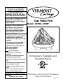
Homeowner’s Installation and
Operating Manual
Gas Patio Fire
Models: GPFMN, GPFMP
INSTALLER: Do Not Discard This Manual
Leave for Homeowner
20004237 / 0901
4237
IMPORTANT: Installation of natural
gas should be completed by a
qualified installer, service agency
or gas supplier.

2
Vermont Castings GPF
Table of Contents
Specifications ....................................................2
General Information ..........................................3
Assembly & Installation ..................................... 4
Log Placement ..................................................7
Operation ..........................................................9
Maintenance....................................................10
Replacement Parts.......................................... 11
Accessories.....................................................12
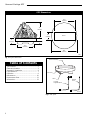
11¹⁄₂"
(292mm)
5"
(127mm)
12"
(305mm)
3¹⁄₄"(83mm)
16¹⁄₄"
(413mm)
11³⁄₈"
(289mm)
8¹⁄₄"
(210mm)
Burner
GPF Dimensions
4237
Fig. 1 Physical dimensions.
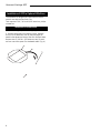
Burner Assembly
Propane
Regulator/Hose
Flex Line
Valve
Natural
Hose
Fig. 2 GPF parts.
FP1129

3
Vermont Castings GPF
General Information
Model GPF is a decorative gas log set for outdoor use
only. This appliance must not be used for cooking.
IMPORTANT: Read all instructions and warnings
carefully before starting installation. Failure to follow
these instructions may result in a possible fire hazard
and will void the warranty.
WARNING: Improper installation, adjustment,
alteration, service or maintenance can cause injury or
property damage. Read the installation, operating and
maintenance instructions thoroughly before installing or
servicing this equipment.
WARNING: This appliance shall be used only outdoors
in a well-ventilated space and shall NOT be used inside
a building, garage or any other enclosed area.
WARNING: This log set must NOT be installed in an
unvented appliance.
WARNING: This unit is not for use with solid fuel.
NOTE: All new LP cylinders (and in many cases used
cylinders) may contain water, air or other contaminants,
and it is essential that these be removed before filling
the cylinder and placing into service. Water vapor
present in the gas vapor may cause the regulator to
“freeze up” and cause an interruption to the gas flow.
This interruption will cause the unit to shut down. To
prevent this form occurring it is essential that a
qualified individual ALWAYS purge a new tank
thoroughly before placing it into service. It is
recommended that cylinders that have not been used
for extended periods of time also be purged before use.
The installation must conform with Local Codes or, in
the absence of local codes, with the National Fuel Gas
Code ANSI Z223.1 or CSA-B149.1 Installation Code.
The appliance and its individual shut off valve must be
disconnected from the gas supply piping system during
any pressure testing or the system at test pressures in
excess of 1/2 psig (3.5kPa).
This appliance must be isolated from the gas supply
piping system by closing its individual manual shut off
valve during any pressure testing of the gas supply
piping system at test pressures equal to or less than 1/
2 psig (3.5kPa).
The following clearances to combustible construction
must be maintained: Bottom - 0 inches (0mm), Sides
(all around) - 16 inches (406mm) and Top - (7 feet
(2.1m).
Always keep the appliance area clear and free from
combustible materials, gasoline and other flammable
vapors and liquids.
Do not locate appliance where it can get excessively
wet. Do not use this appliance if any part has been
under water. Immediately call a qualified service
technician to inspect the unit and to replace any part of
the control system and any gas control which has been
under water.
• Children and adults should be alerted to the hazards
of high surface temperatures and should stay away to
avoid burns or clothing ignition.
• Young children should be carefully supervised when
they are in the area of the appliance.
• Never leave unit unattended during operation.
• Clothing or other flammable materials should not be
hung from the appliance, or placed on or near the
appliance.
• Any guard or other protective device removed for
servicing the appliance must be replaced prior to
operating the appliance.
• Installation and repair should be done by a qualified
service person. The appliance should be inspected
before use and at least annually by a qualified service
person. More frequent cleaning may be required as
necessary. It is imperative the control compartment,
burners and circulating air passageways of the
appliance be kept clean.
• Inspect the fuel supply connection (including the hose
for LP models) before each use of the appliance.
• If it is evident there is excessive abrasion or wear, or
the hose is cut, it must be replaced prior to the
appliance being put into operation.
• The pressure regulator and hose assembly supplied
with LP models must be used. Replacement pressure
regulators and hose assemblies must be those
specified in this manual.
• The LP gas supply cylinder used with LP models must
be constructed and marked in accordance with the
specifications for LP gas cylinders of the U.S.
Department of Transportation (DOT).
• Cylinders must be stored outdoors in a well-ventilated
area out of reach of children. Disconnected cylinders
must have threaded valve plugs tightly installed and
must not be stored in a building, garage or any other
enclose area.
• Storage of this appliance indoors is permissible only
it has been disconnected from its fuel supply (natural
gas line or LP gas cylinder).
• The LP gas cylinder supply system must be arranged
for vapor withdrawal.
• The LP gas cylinder used must include a collar to
protect the cylinder valve.
• When an LP model is not in use, the LP gas must be
turned off at the supply cylinder.

4
Vermont Castings GPF
Assembly and Installation
The logs and burner assembly are shipped together.
1. Remove the gas log set and burner assembly and
check for damage. DO NOT install damaged
components. The logs are fragile - handle with care.
2. Place the burner assembly on a flat, stable surface
in an outdoor location such as a patio or a deck.
This location must be adjacent to the gas supply line
(natural gas) or LP gas supply cylinder. NOTE:
Minimum clearances to combustibles must be
maintained.
Remember, you must have easy access to the gas
valve control knob AFTER the appliance is installed
and connected to the gas supply.
The ON/OFF Gas Valve is used to turn the burner
on and off.
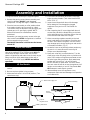
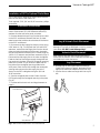
Natural Gas Models
Connect the incoming gas supply line to the on/off gas
valve of the appliance. (Fig. 3) Make certain ALL gas
connections are tight. Test for leaks. Use a 50/50
solution of liquid soap and water to test for leaks at gas
fittings and joints. Apply water/soap solution with a
brush only -
do not over apply. NEVER test with an
open flame.
LP Gas Models
1. Place cylinder base (provided with unit) on a level
surface.
2. Be sure to place cylinder in ring on base.
3. Make sure tank valve is in its full off position. (Turn
clockwise to stop)
4. Check tank valve features to ensure it has proper
external mating threads. (Tank valve Marked: USE
WITH TYPE 1)
5. Inspect hose shipped with the unit for damage.
Never attempt to use damaged or plugged
equipment. See your local LP Gas Dealer for
repairs.
6. After inspecting the LP hose shipped with the unit,
connect the end with the female fitting on the hose
to the male fitting on the on/off gas valve at the end
of the flex tube and make sure it is tight.
7. When connecting regulator assembly to the tank
valve, hand tighten nut clockwise to a positive stop.
DO NOT use a wrench to tighten. Use of a wrench
may damage quick closing coupling nut and result in
a hazardous condition. (Fig. 3)
8. Locate the hose out of pathways where people may
trip over it or in areas where the hose may be
subject to accidental damage.
9. Open tank valve fully (counterclockwise). Turn the
on/off valve at the unit slowly to the on position and
use a 50/50 solution of liquid soap and water to test
for leaks at gas fitting and joints. Apply water/soap
solution with a brush only - do not over apply.
NEVER test with an open flame. If a leak is found,
turn tank valve off and do not use the appliance until
repairs can be made by a local LP Gas Dealer. DO
NOT attempt to make repairs yourself.
10. Never attempt to use this appliance or any
components that have been damaged or exposed to
an accidental fire.
Natural Gas Supply Line
Burner Assembly
Propane
Regulator Hose
Burner
Assembly
FP1130
Fig. 3 Gas line connection.
Valve
Valve
Cylinder Base

5
Vermont Castings GPF
Enclosures for LP Gas Supply Systems
If you build an enclosure for an LP gas cylinder, follow
these recommended specifications. You must also
follow local codes.
Enclosures for LP gas supply cylinders shall be
ventilated by openings at the level of the cylinder valve
and at floor level. The effectiveness of the opening(s)
for purposes of ventilation shall be determined with the
LP gas supply cylinder(s) in place. This shall be
accomplished by one of the following:
1. One side of the enclosure shall be completely open;
or
2. For an enclosure having four sides, a top and
bottom:
a. At least two ventilation openings at cylinder valve
level shall be provided in the side wall, equally sized,
spaced at 180 degrees (3.14 rad), and unobstructed.
Each opening shall have a total free area of not less
than 1/2 square inch per pound (3.2 sq. cm/kg) of
stored fuel capacity and not less than a total free
area of 10 square inches (64.5sq. cm).
b. Ventilation opening(s) shall be provided at floor level
and shall have a total free area of not less than 1/2
inch per pound (3.2 sq. cm/kg) of stored fuel
capacity and not less than a total free area of 10
square inches (64.5 sq. cm). If ventilation openings
at floor level are in a side wall, there shall be at least
two openings. The bottom of the openings shall be
at floor level and the upper edge no more than 5
inches (127mm) above the floor. The openings shall
be equally sized, spaced at 180 degrees (3.14 rad)
and unobstructed.
c. Every opening shall have minimum dimensions so
as to permit the entrance of a 1/8 inch (3.2mm)
diameter rod.
3. Cylinder valves shall be readily accessible for hand
operation. A door on the enclosure to gain access to
the cylinder valves is acceptable, provided it is
nonlocking and can be opened without the use of
tools.
4. There shall be a minimum clearance of 2 inches
(50.8 mm) between the lower surface of the floor of
the LP gas supply cylinder enclosure and the
ground.
5. The design of the enclosure shall be such that (1)
the LP gas supply cylinder(s) can be connected,
disconnected and the connections inspected and
tested outside the cylinder enclosure; and (2) those
connections which could be disturbed when
installing the cylinder(s) in the enclosure can be leak
tested inside the enclosure.
6. Be certain to mount or set the LP gas cylinder on a
flat stable surface and restrain it to prevent it from
tipping.
Purge the gas supply line of any trapped air prior to the
first firing of the unit.
WARNING: During the initial purging and
subsequent lightings, NEVER allow gas valve to
remain in the “Open” position without first placing
a burning match on the top of the burner.
Place the logs on the burner assembly. Refer to log
placement instructions.
Test fire the unit after referring to the SAFETY
INFORMATION and Lighting Instructions found on page
9.
CAUTION: Do not leave the burner on with the
cover on.
NOTE: Carbon (soot) may build up on the surface of
the logs with heavy use. This is more likely to occur
when using LP gas. The soot should be cleaned off the
surface of the logs periodically to prevent excessive
build up. To clean the logs, be sure the fire is out, the
gas supply is turned off and the logs are cool to the
touch. The soot can then be brushed off with a dry
bristle brush or cloth. Take care while cleaning the logs
as they can become damaged if mishandled. Care
should be taken to dispose of the soot and cleaning
materials properly. Keep away from clothing and
outdoor furniture.

6
Vermont Castings GPF
Installation of GPF in Optional Villa Base
The Villa Base is designed as a decorative enhance-
ment for use with the Gas Patio Fire.
Tools required: 7/16”, 3/4” and 11/16” wrenches, phillips
screwdriver.
Installation Instructions
1. Remove octagonal plate from shipping carton.
2. Remove base/Villa from shipping carton. Remove
four (4) 1/4-20 fasteners, four (4) nuts and eight (8)
washers that fasten the base to the Villa. Remove base.
Remove two (2) 1/4-20 x 1/2” fasteners, two (2) wash-
ers from cast valve panel. Set hardware aside. (Fig. 4)

7
Vermont Castings GPF
Installation of GPF in Optional Chalet Base
The Chalet Base is designed as a decorative enhance-
ment for use with the Gas Patio Fire.
Tools required: 7/16”, 3/4” and 11/16” wrenches, phillips
screwdriver.
Installation Instructions
1. Remove Chalet Base assembly from shipping
carton. Remove two (2) 1/4-20 fasteners and two (2)
washers from the cast valve panel, set aside.
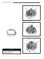
2. Remove decorative brass ring from the burner valve
on the GPF and discard. Remove the four (4) sheet
metal screws that hold the valve brackets to the burner
on the GPF and discard.
3. Disconnect the fuel supply line from the valve using
a 3/4” wrench. (Fig. 7) Using both the 3/4” and 11/16”
wrenches, remove the fuel supply line from the venturi
(tube secured to the bottom of the burner). Assemble
the valve and bracket assembly to the Chalet using the
1/4-20 x 1/2” fasteners and washers removed in Step 2.
Reconnect the fuel supply line to the valve and tighten.
Feed the fuel line from the gas supply through the fuel
line opening in the base. Place the octagonal mounting
plate on the Chalet. (Fig. 8) Orient the plate with the
long side of the rectangular opening parallel to the
valve panel. Pass the fuel line through the rectangular
opening and reconnect the fuel supply line to the
venturi on the GPF and tighten using the 3/4” and
11/16” wrenches.
6. Seat the octagonal plate on the Chalet. Pass the
GPF legs through the rectangular opening in the plate.
(Fig. 8)
7. Continue with volcanic rock and log placement on
page 8.
Cast Valve Panel
Valve
Valve Brackets
KT264
Fig. 7 Attach valve and brackets to cast valve brackets.
Log & Volcanic Rock Placement
Remove logs from packaging and examine each for
damage. If any logs are damaged or missing, contact
your dealer. DO NOT install damaged logs.
Volcanic Rock Placement
Pour volcanic rock into outer ring and over burner.
Make sure the volcanic rock is level with the outer ring
and builds up to cover the burner.
Log Placement
1. Arrange logs on floor near burner according to
Figure 9. As shown in Figure 9, the bottom of the
logs will be toward the outside of the burner ring.
2. Use flex line as reference. Begin with line to your
left.

8
Vermont Castings GPF
The logs are fragile. Use caution when placing
the cover on, or removing the cover from, the unit
to avoid damaging the logs.
CAUTION
Log C4
Log C5
Log C1
Log C2
LG165a
Fig. 14 Log C5 placement.
Log C5
Log C1
Log C6
Log C4
Log
C2
Log C3
LG166a
Fig. 15 Log C6 placement.
Log C4
Log C2
Log C1
Log C3
LG164a
Fig. 13 Logs C3 & C4 placement.

9
Vermont Castings GPF
Upon completing the gas line connection, a small
amount of air will be in the lines. When first lighting the
burner, it will take a few minutes for the lines to purge
themselves of this air. Once the purging is complete,
the burner will light and operate as indicated in the
instruction manual. Subsequent lighting of the
appliance will not require such purging.
Operation
WARNING: Read and follow the Safety and Lighting
Instructions page in this manual and on labels on the
appliance. IF YOU DO NOT FOLLOW THESE
INSTRUCTIONS PRECISELY, A FIRE OR EXPLOSION
MAY RESULT AND YOU MAY BE SERIOUSLY
INJURED!
FOR YOUR SAFETY READ BEFORE LIGHTING
• If you cannot reach your gas supplier, call the
Fire Department
C. Use only your hand to push in or turn the gas
control knob. Never use tools. If the knob will not
push in or turn by hand, do not try to repair it, call
a qualified service technician. Applying force or
any attempted repair may result in a fire or
explosion.
D. Do not use this appliance if any part has been
under water. Immediately call a qualified service
technician to inspect the appliance and to replace
any part of the gas control which has been under
water.
A. This outdoor cooking appliance must be lit
manually. When lighting, follow these instruc-
tions exactly.
B. BEFORE LIGHTING smell all around the
appliance area for gas. Be sure to smell next to
the floor because some gas is heavier than air
and will settle on the floor.
WHAT TO DO IF YOU SMELL GAS
• Do not try to light any fireplace
• Do not touch any electric switch
• Do not use any phone in your building
• Immediately call your gas supplier from a
neighbor's phone. Follow the gas supplier's
instructions.
Lighting And Operating Instructions
Lighting Instructions
WARNING:If you do not follow these instructions exactly, a fire or explosion
may result causing property damage, personal injury or loss of life.
1. STOP! Read the safety information above.
2. Remove the cover.
3. Insert the “TEE” handle in the valve.
4. Place a burning match on top of burner in the middle
where ports are present. DO NOT HOLD THE
MATCH IN HAND.
• For Natural Gas unit, turn the “TEE” handle
slowly counterclockwise.
• For LP unit, turn valve on the LP tank
counterclockwise all the way and then turn the
“TEE” handle on the valve slowly
counterclockwise.
5. If the burner does not light before the match goes
out, immediately turn the gas valve to “OFF”.
6. Wait at least five (5) minutes to clear out any gas. If
you have unsuccessfully tried to light the burner,
wait longer. Then smell for gas, including near the
floor. If you smell gas, STOP! Follow “B” in the safety
information above. If you do not smell gas, repeat step
4.
To Turn Off Gas To Heater
1. Turn the valve to the “OFF” position at the unit for
natural gas unit. For LP unit, turn the valve to the
“OFF” position, fully clockwise at the unit, then
turn the valve on the LP tank to the “OFF” position,
clockwise .
2. Replace the cover.

10
Vermont Castings GPF
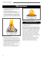
Maintenance
1. The appliance should be inspected before initial use
and inspected and cleaned at least annually by a
qualified field service person.
2. Tampering is DANGEROUS and voids all
warranties. Any component that is found to be faulty,
must be replaced with an approved component.
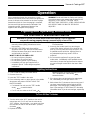
3. To obtain proper operation, it is imperative that the
burner flame characteristics are steady, not lifting or
floating. Check the burner flame patterns with Figure
13.
4. Periodically remove the logs and examine the
burner. If dirty, clean with a soft brush. Also examine
the area around the burner air shutter. Any dirt or lint
in this area should be removed. This will ensure long
life and trouble free operation. When the appliance
is put back in service, check the burner flame
patterns with Figure 17. Reinstall the logs as shown
in the log placement instructions.
5. Periodically check the hose connecting the LP gas
cylinder to ensure it is not damaged in any way.
High Elevation Installation
This U.L. listed gas appliance is tested and approved
for elevations form 0 to 2,000 feet in the US and from 0
to 4,500 feet in Canada.
When installing this appliance at an elevation above
2,000 feet (in the US), it may be necessary to decrease
the input rating by changing the existing burner orifice
to a smaller size. Input should be reduced four percent
(4%) for each 1,000 feet above sea level, unless the
heating value of the gas has been reduced, in which
case this general rule will not apply. To identify the
proper orifice size, check with the local gas utility.
When installing this fireplace at an elevation between
2,000 and 4,500 feet (in Canada), the input rating must
be reduced by ten percent (10%).
When installing this fireplace at an elevation above
4,500 feet (in Canada), check with local authorities.
Consult your local gas utility for assistance in
determining the proper orifice for your location.
LG168
Fig. 16 GPF flame appearance.
Fig. 17 Correct burner flame appearance.
LG169

11
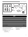
Vermont Castings GPF
1
ab
c
d
e
f
2
3
4
5
6
8
7a,b
9
The Vermont Castings Majestic Products Company reserves the right to make changes in design, materials, specifications, prices and discontinue
colors and products at any time, without notice.
4237
GPF
Item / Model Number Part Number
1. Complete Log Set 20004457
1a. Log C1 20004451
1b. Log C2 20004452
1c. Log C3 20004454
1d. Log C4 20004453
1e. Log C5 20004455
1f. Log C6 20004456
2. Burner Assy. 20003733
3. Hose/Regulator Assy. - LP 50000248
4. Cover 20004450
5. Dante Valve 20004482
6. Natural Supply Line 50000198
7a. Short Stem Orifice - Natural 20004497
7b. Short Stem Orifice - LP 20004498
8. Volcanic Rock 20000198
9. LP Gas Cylinder Base 20004578
10. LP Conversion Kit 20004752
11. NG Conversion Kit 20004753
Contact The Vermont Castings Majestic Products
Company with questions concerning prices and
policies covering replacement parts. Parts may be
ordered through your distributor or dealer.
You will need the following information when ordering
replacement parts:
• The appliance model number.
• The serial number.
• A description of the part.
Should you need additional information beyond what
your dealer can furnish, contact:
The Vermont Castings Majestic Products Company
410 Admiral Blvd.
Mississauga, Ontario
Canada L5T 2N6

12
Vermont Castings GPF
Accessories
The following accessories for these appliances are available form your local Vermont Castings Majestic Products
Company distributor. Each accessory comes with a separate installation instruction for the particular appliance. Be
sure to read each instruction thoroughly before installing.
Description Model Number
Patio Fire Optional Safety Screen Kit PFOSK
Villa Patio Fire (Urn) Base PFCBUMB
Chalet Patio Fire (Octagonal) Base PFCBOMB
CAUTION: This appliance is a highly engineered system, and, as such, must be operated only with The
Vermont Castings Majestic Products Company approved components. If you use an unapproved component
to make any modifications, you may create a possible fire hazard and will void the Vermont Castings Majestic
Products Company warranty. In addition, such action may void the coverage provided by the owner’s
insurance.

13
Vermont Castings GPF
BASIC WARRANTY:
The Vermont Castings, Majestic Products Company (hereinafter referred to
collectively as the "Company") warrants that your new Vermont Castings Gas
Appliance is free from manufacturing and material defects for a period of one
year from date of installation, subject to the following conditions and
limitations.
EXTENDED LIFE TIME WARRANTY:
The heat exchanger, combustion chamber and ceramic burner parts of every
*The Vermont Castings, Majestic Products Company products are warranted
for life to the original owner, subject to proof of purchase and the following
conditions and limitations:
1.
This new Vermont Castings product must be installed by a competent,
authorized service contractor. It must be installed and operated at all times in
accordance with the Installation and Operating instructions furnished with the
product. Any alteration, willful abuse, accident, or misuse of the product shall
nullify this warranty.
2.
This warranty is non-transferrable, and is made to the original owner, provided
that the purchase was made through an authorized supplier of the Company.
3.
This warranty is limited to the repair or replacement of part(s) found to be
defective in material or workmanship, provided that such part(s) have been
subjected to normal conditions of use and service, after said defect is confirmed
by the Company's inspection.
4.
The Company may, at its discretion, fully discharge all obligations with respect
to this warranty by refunding the wholesale price of the defective part(s).
5.
Any installation, labour, construction, transportation, or other related costs/
expenses arising from defective part(s), repair, replacement, or otherwise of
same, will not be covered by this warranty, nor shall the Company assume
responsibility for same. Further, the Company will not be responsible for any
incidental, indirect, or consequential damages, except as provided by law.
6.
All other warranties - expressed or implied - with respect to the product, its
components and accessories, or any obligations/liabilities on the part of the
Company are hereby expressly excluded.
7.
The Company neither assumes, nor authorizes any third party to assume, on
its behalf, any other liabilities with respect to the sale of this Vermont Castings
product.
8.
The warranties as outlined within this document do not apply to chimney
components or other non Vermont Castings accessories used in conjunction
with the installation of this product.
9.
The Company will not be responsible for . . .
a) Down drafts or spillage caused by environmental conditions such as near-
by trees, buildings, roof tops, hills, or mountains.
b) Inadequate ventilation or negative air pressure caused by mechanical
systems such as furnaces, fans, clothes dryers, etc.
10.
This warranty is void if:
a) The fireplace has been operated in atmospheres contaminated by chlorine,
fluorine or other damaging chemicals.
b) The fireplace is subjected to prolonged periods of dampness or
condensation.
c) Any damage to the fireplace, combustion chamber, heat exchanger or other
components due to water, or weather damage which is the result of, but
not limited to, improper chimney/venting installation.
d) Any alteration, willful abuse, accident, or misuse of the product.
GLASS DOORS & BRASS PLATED PARTS
Glass doors are not warranted for breakage due to misuse or accident.
Brass parts should be cleaned with lemon oil only. Brass cleaners cannot be used.
Mortar mix and masonry cleaners may corrode the brass finish. The Company will
not be responsible for, nor will it warrant any brass parts which are damaged by
external chemicals or down draft conditions.
IF WARRANTY SERVICE IS NEEDED . . .
1) Contact your supplier. Make sure you have your warranty, your sales receipt,
and the model/serial number of your Vermont Castings product.
2) DO NOT ATTEMPT TO DO ANY SERVICE WORK YOURSELF.
GARANTIE DE BASE:
The Vermont Castings, Majestic Products Company (aux présentes nommée
la "Société") garantit votre nouveau foyer au gaz Vermont Castings contre
tous défauts de fabrication et de matières premières pour une période d'un an
à compter de la date d'installation, sujet aux conditions et limitations suivantes.
GARANTIE A VIE PROLONGEE:
Les pièces de l'échangeur de chaleur, de la chambre à combustion et du brûleur
en céramique de tout produit *The Vermont Castings, Majestic Products
Company sont garanties pour la vie de l'acheteur d'origine, le tout sujet à une
preuve d'achat et aux conditions et limitations suivantes:
1.
Ce nouveau produit Vermont Castings doit être installé par un entrepreneur
de service autorisé et compétent. Il doit être installé et utilisé en tout temps
selon les instructions d'installation et de fonctionnement fournies avec le produit.
Toute altération, abus volontaire, accident ou mauvais usage du produit annulera
cette garantie.
2.
Cette garantie n'est pas transférable et est offerte à l'acheteur au détail d'origine,
à condition que l'achat soit effectué par l'entremise d'un détaillant autorisé de la
Société.
3.
Cette garantie est limitée à la réparation ou au remplacement de(des) pièce(s)
trouvée(s) défectueuse(s) en matières premières ou main-d'oeuvre, à condition
que lesdites pièces aient été sujettes aux conditions normales d'usage et de
service, après que ledit défaut a été confirmé par une inspection par la Société.
4.
La Société peut, à sa discrétion, se décharger entièrement de toutes obligations
se rapportant à cette garantie en remboursant le prix de gros de la(des) pièce(s)
défectueuse(s).
5.
Tous les frais/dépenses d'installation, de main-d'oeuvre, de construction, de
transport ou autres causés par une (des) pièce(s) défectueuse(s), une réparation,
un remplacement ou autre, ne seront pas couverts sous cette garantie, et la
Société n'assume aucune responsabilité pour ceux-ci. De plus, la Société ne
pourra être tenue responsable pour tous dommages fortuits ou indirects sauf la
ou prévu par la loi.
6.
Toutes autres garanties, exprimées ou sous-entendues, en ce qui a trait au
produit, ses composants et accessiores, ou toutes obligations/responsabilités
de la part de la Société sont aux présentes expressment excluses.
7.
La Société n'assume et n'autorise personne à assumer, en son nom, toutes
responsabilités en ce qui a trait à la vente de ce produit Vermont Castings.
8.
Les garanties, telles que décrites dans ce document, ne s'appliquent pas aux
compasants de cheminée ou aux autres accessoires non Vermont Castings
utilisés conjointement pour l'installation de ce produit.
9.
La Société n'encourrera aucune responsabilité pour . . .
a) Les refoulements de cheminées ou débordements causés par les conditions
environnementales comme par les arbres, les édifices, les toits, les côteaux
ou les montagnes adjacents.
b) Une ventilation inadéquate ou une pression d'air négative causée par des
systèmes mécaniques comme les fournaises, les ventilateurs, les
sécheuses, etc.
10.
Cette garantie est nulle si:
a) Le foyer a été utilisé dans une atmosphère contaminée par du chlore, du
fluor ou tous autres produits chimiques.
b) Le foyer est assujetti à de longues périodes d'humidité ou de condensation.
c) Des dommages sont causés au foyer, à la chambre de combustion. à
l'échangeur de chaleur ou aux autres composants par de l'eau ou par la
température qui est le résultat mais sans y être limité, d'une mauvaise
installation de cheminée/ventilation.
d) Toute altération, abus volontaire, accident ou mauvais usage du produit
annulera cette garantie.
PORTES EN VERRE & PIECES PLAQUEES LAITON
Les portes en verre ne sont pas garanties contre le bris causé par un mauvais
usage ou un accident.
Les pièces en laiton devraient être nettoyées qu'avec de l'essence de citron. Les
nettoyeurs de laiton ne peuvent pas être utilisés. La Société ne sera pas responsable
pour, et ne garantit pas les pièces en laiton qui sont endommagées par des conditions
chimiques externes ou de refoulement.
SI UN SERVICE SOUS GARANTIE EST REQUIS . . .
1. Communiquez avec votre détaillant. Assurez-vous que vous avez votre garantie,
votre reçu de caisse ainsi que le numéro de modèle/série de votre produit
Vermont Castings.
2. NE TENTEZ PAS D'EFFECTUER DES REPARATIONS VOUS-MEME.
*Les foyers à gaz The Vermont Castings, Majestic Products
Company portant ce scean d'approbatic de la garantie
spéciale sont couverts par une garantie limitée à vie. Celle- ci
inclue les brüleurs en céramique Insta-Flame, le'échangeur de
chaleur et la chambre à combustion. Toutes les autres
pièces sont couverte pour un an.
LIMITED WARRANTY & EXTENDED LIFE TIME PROTECTION
For Vermont Castings Gas Appliance Products*
410 Admiral Blvd.
Mississauga ON L5T 2N6
*The Vermont Castings, Majestic Products Company products
bearing this special Warranty Seal of Approval carry a
comprehensive Limited Lifetime Warranty. This includes the
Insta-
Flame
Ceramic Burners, Heat Exchange System and Combustion
Chamber. All other parts are covered for one year.

14
Vermont Castings GPF
410 Admiral Blvd. • Mississauga, Ontario, Canada L5T 2N6 • 905-670-7777
www.majesticproducts.com • www.vermontcastings.com
The Vermont Castings
Majestic Products Company
© The Vermont Castings Majestic Products Company
-
 1
1
-
 2
2
-
 3
3
-
 4
4
-
 5
5
-
 6
6
-
 7
7
-
 8
8
-
 9
9
-
 10
10
-
 11
11
-
 12
12
-
 13
13
-
 14
14


Majestic Appliances GPFMN Manuel utilisateur
- Catégorie
- Cheminées
- Taper
- Manuel utilisateur
- Ce manuel convient également à
dans d''autres langues
Autres documents
-
Vermont Castings GPFMP Manuel utilisateur
-
-
 Filter Queen Majestic High-Filtration Surface Cleaner Manuel utilisateur
-
Majestic fireplaces Woodland UVLC24RN Installation And Operating Instructions Manual
-
HearthStone Tudor 8120 Le manuel du propriétaire
-
-
-
-
-
