Gossen MetraWatt SINEAX AM3000 Mode d'emploi
- Catégorie
- Mesure, test
- Taper
- Mode d'emploi


PM 1000162 000 09 Device handbook SINEAX AM3000 2/86
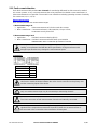
Warning notices
In this document warning notices are used, which you have to observe to ensure personal safety and to prevent
damage to property. Depending on the degree of danger the following symbols are used:
If the warning notice is not followed death or severe personal injury
will result.
If the warning notice is not followed damage to property or severe
personal injury may result.
If the warning notice is not followed the device may be damaged or
may not fulfill the expected functionality.
Qualified personnel
The product described in this document may be handled by personnel only, which is qualified for the respective
task. Qualified personnel have the training and experience to identify risks and potential hazards when working
with the product. Qualified personnel are also able to understand and follow the given safety and warning
notices.
Intended use
The product described in this document may be used only for the application specified. The maximum electrical
supply data and ambient conditions specified in the technical data section must be adhered. For the perfect and
safe operation of the device proper transport and storage as well as professional assembly, installation,
handling and maintenance are required.
Disclaimer of liability
The content of this document has been reviewed to ensure correctness. Nevertheless it may contain errors or
inconsistencies and we cannot guarantee completeness and correctness. This is especially true for different
language versions of this document. This document is regularly reviewed and updated. Necessary corrections
will be included in subsequent version and are available via our webpage http://www.camillebauer.com
.
Feedback
If you detect errors in this document or if there is necessary information missing, please inform us via e-mail to:
customer-support@camillebauer.com

PM 1000162 000 09 Device handbook SINEAX AM3000 3/86
Contents
1. Introduction ................................................................................................................................. 5
1.1 Purpose of this document ........................................................................................................ 5
1.2 Scope of supply ....................................................................................................................... 5
1.3 Further documents .................................................................................................................. 5
2. Safety notes ................................................................................................................................. 6
3. Device overview .......................................................................................................................... 6
3.1 Brief description ....................................................................................................................... 6
3.2 Available measurement data ................................................................................................... 6
4. Mechanical mounting .................................................................................................................. 7
4.1 Panel cutout ............................................................................................................................ 7
4.2 Mounting of the device ............................................................................................................ 7
4.3 Demounting of the device ........................................................................................................ 7
5. Electrical connections ................................................................................................................ 8
5.1 General safety notes ............................................................................................................... 8
5.2 Terminal assignments of the I/O extensions ............................................................................ 9
5.3 Possible cross sections and tightening torques ....................................................................... 9
5.4 Inputs .................................................................................................................................... 10
5.5 Power supply ......................................................................................................................... 22
5.6 Relays ................................................................................................................................... 22
5.7 Digital inputs .......................................................................................................................... 22
5.8 Digital outputs ....................................................................................................................... 23
5.9 Analog outputs ...................................................................................................................... 24
5.10 Modbus interface RS485 ....................................................................................................... 24
5.11 Fault current detection ........................................................................................................... 25
5.12 Uninterruptible power supply (UPS) ..................................................................................... 27
5.13 GPS time synchronization ................................................................................................. 28
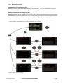
6. Commissioning ......................................................................................................................... 30
6.1 Parametrization of the device functionality ............................................................................. 30
6.2 Installation check ................................................................................................................... 30
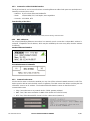
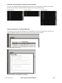
6.3 Ethernet installation ............................................................................................................... 32
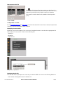
6.3.1 Settings ......................................................................................................................... 32
6.3.2 Connection of the standard interface ............................................................................. 34
6.3.3 Connection of the IEC61850 interface ........................................................................... 35
6.3.4 MAC addresses ............................................................................................................. 35
6.3.5 Communication tests ..................................................................................................... 35
6.4 Simulation of analog / digital outputs ..................................................................................... 36
6.5 Protection against device data changing ............................................................................... 36
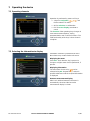
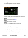
7. Operating the device ................................................................................................................. 37
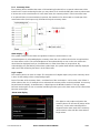
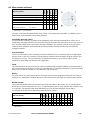
7.1 Operating elements ............................................................................................................... 37
7.2 Selecting the information to display ....................................................................................... 37
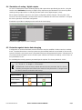
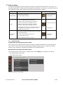
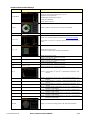
7.3 Measurement displays and used symbols ............................................................................. 38
7.4 Resetting measurement data ................................................................................................. 40
7.5 Configuration ......................................................................................................................... 40
7.5.1 Configuration at the device .............................................................................................. 40
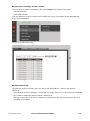
7.5.2 Configuration via web browser ........................................................................................ 41
7.6 Alarming ................................................................................................................................ 43
7.6.1 Limit values on base quantities ...................................................................................... 43
7.6.2 Monitoring fault-currents ................................................................................................ 44

PM 1000162 000 09 Device handbook SINEAX AM3000 4/86
7.6.3 Monitoring functions ...................................................................................................... 45
7.6.4 Summary alarm ............................................................................................................. 46
7.7 Data recording ...................................................................................................................... 47
7.7.1 Periodical data .............................................................................................................. 47
7.7.2 Events ........................................................................................................................... 50
7.7.3 Disturbance recorder ..................................................................................................... 51
7.7.4 Micro SD card ............................................................................................................... 53
7.8 Timeouts ............................................................................................................................... 54
8. Service, maintenance and disposal ......................................................................................... 55
8.1 Calibration and new adjustment ............................................................................................ 55
8.2 Cleaning................................................................................................................................ 55
8.3 Battery .................................................................................................................................. 55
8.4 Disposal ................................................................................................................................ 55
9. Technical data ........................................................................................................................... 56
10. Dimensional drawings .............................................................................................................. 62
Annex .............................................................................................................................................. 63
A Description of measured quantities ........................................................................................ 63
A1 Basic measurements............................................................................................................. 63
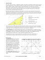
A2 Harmonic analysis ................................................................................................................. 67
A3 System imbalance ................................................................................................................. 68
A4 Mean values and trend .......................................................................................................... 69
A5 Meters ................................................................................................................................... 70
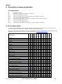
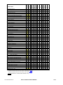
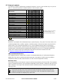
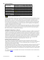
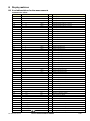
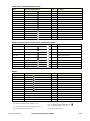
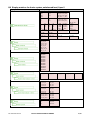
B Display matrices ....................................................................................................................... 71
B0 Used abbreviations for the measurements ............................................................................ 71
B1 Display matrices for single phase system .............................................................................. 75
B2 Display matrices for split-phase (two-phase) systems ........................................................... 76
B3 Display matrices for 3-wire system, balanced load ................................................................ 77
B4 Display matrices for 3-wire system, balanced load, phase shift ............................................. 78
B5 Display matrices for 3-wire systems, unbalanced load .......................................................... 79
B6 Display matrices for 3-wire systems, unbalanced load, Aron ................................................. 80
B7 Display matrices for 4-wire system, balanced load ................................................................ 81
B8 Display matrices for 4-wire systems, unbalanced load .......................................................... 82
B8 Display matrices for 4-wire system, unbalanced load, Open-Y .............................................. 83
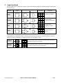
C Logic functions ......................................................................................................................... 84
D FCC statement .......................................................................................................................... 85
INDEX .............................................................................................................................................. 86

PM 1000162 000 09 Device handbook SINEAX AM3000 5/86
1. Introduction
1.1 Purpose of this document
This document describes the universal measurement device for heavy-current quantities SINEAX
AM3000. It is intended to be used by:
• Installation personnel and commissioning engineers
• Service and maintenance personnel
• Planners
Scope
This handbook is valid for all hardware versions of the AM3000. Some of the functions described in this
document are available only, if the necessary optional components are included in the device.
Required knowledge
A general knowledge in the field of electrical engineering is required. For assembly and installation of the
device knowledge of applicable national safety regulations and installation standard is required.
1.2 Scope of supply
• Measurement device SINEAX AM3000
• Safety instructions (multiple languages)
• Mounting set: 2 mounting clamps
• Battery pack (optional, for devices with UPS only)
1.3 Further documents
The following documents are provided electronically via http://www.camillebauer.com/am3000-en :
• Safety instructions SINEAX AM2000 / SINEAX AM3000
• Data sheet SINEAX AM1000/AM2000/AM3000
• Modbus basics: General description of the communication protocol
• Modbus interface SINEAX AMx000: Register description of Modbus communication
• IEC61850 interface SINEAX AMx000/DM5000, LINAX PQx000, CENTRAX CUx000

PM 1000162 000 09 Device handbook SINEAX AM3000 6/86
2. Safety notes
Device may only be disposed in a professional manner!
The installation and commissioning should only be carried out by trained personnel.
Check the following points before commissioning:
– that the maximum values for all the connections are not exceeded, see "Technical data"
section,
– that the connection wires are not damaged, and that they are not live during wiring,
– that the power flow direction and the phase rotation are correct.
The instrument must be taken out of service if safe operation is no longer possible (e.g. visible
damage). In this case, all the connections must be switched off. The instrument must be
returned to the factory or to an authorized service dealer.
It is forbidden to open the housing and to make modifications to the instrument. The instrument
is not equipped with an integrated circuit breaker. During installation check that a labeled switch
is installed and that it can easily be reached by the operators.
Unauthorized repair or alteration of the unit invalidates the warranty.
3. Device overview
3.1 Brief description
The SINEAX AM3000 is a comprehensive instrument for the universal measurement and monitoring in
power systems. A full parameterization of all functions of the device is possible directly at the device or via
web browser. The universal measurement system of the device may be used directly for any power
system, from single phase up to 4-wire unbalanced networks, without hardware modifications.
Using additional, optional components the opportunities of the device may be extended. You may choose
from I/O extensions, communication interfaces and data logging. The nameplate on the device gives
further details about the present version.
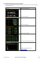
3.2 Available measurement data
The SINEAX AM3000 provides measurements in the following subcategories:
a) Instantaneous values: Present TRMS values and associated min/max values
b) Energy: Power mean-values with trend and history as well as energy meters. With the data logger
option “periodical data” mean-value progressions (load profiles) and periodical meter readings are
available as well.
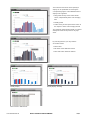
c) Harmonics: Total harmonic distortion THD/TDD, individual harmonics and their maximum values
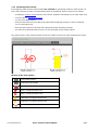
d) Phasor diagram: Overview of all current and voltage phasors and phase sequence check
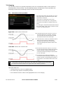
e) Waveform of current and voltage inputs
f) Events: State list of monitored alarms. With the data logger option also chronological lists of events
and alarms as well as operator events are available.

PM 1000162 000 09 Device handbook SINEAX AM3000 7/86
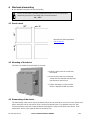
4. Mechanical mounting
► The AM3000 is designed for panel mounting
Please ensure that the operating temperature limits are not exceeded when
determining the place of mounting (place of measurement):
-10 ... 55°C
4.1 Panel cutout
Dimensional drawing AM3000:
See section 10
4.2 Mounting of the device
The device is suitable for panel widths up to 8mm.
a) Slide the device into the cutout from
the outside
b) From the side slide in the mounting
clamps into the intended openings and
pull them back about 2 mm
c) Tighten the fixation screws until the
device is tightly fixed with the panel
4.3 Demounting of the device
The demounting of the device may be performed only if all connected wires are out of service. Remove all
plug-in terminals and all connections of the current and voltage inputs. Pay attention to the fact, that
current transformers must be shortened before removing the current connections to the device. Then
demount the device in the opposite order of mounting (4.2).

PM 1000162 000 09 Device handbook SINEAX AM3000 8/86
5. Electrical connections
Ensure under all circumstances that the leads are free of potential
when connecting them!
5.1 General safety notes
Please observe that the data on the type plate must be adhered to!
The national provisions have to be observed in the installation and material selection of electric lines,
e.g. in Germany VDE 0100 “Conditions concerning the erection of heavy current facilities with rated
voltages below 1000 V”!
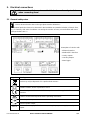
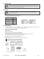
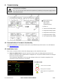
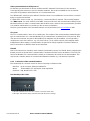
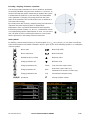
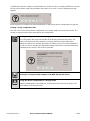
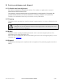
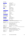
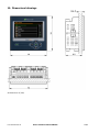
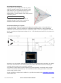
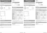
Nameplate of a device with
• Ethernet interface
• Modbus/RTU interface
• 4 relay outputs
• 4 analog outputs
• Data logger
Symbol Meaning
Device may only be disposed of in a professional manner!
Double insulation, device of protection class 2
CE conformity mark. The device fulfills the requirements of the applicable EU
directives.
Caution! General hazard point. Read the operating instructions.
General symbol: Input
General symbol: Output
CAT III
Measurement category CAT III for current / voltage inputs, power supply and relay
outputs

PM 1000162 000 09 Device handbook SINEAX AM3000 9/86
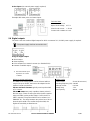
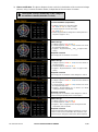
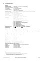
5.2 Terminal assignments of the I/O extensions
Function Option 1 Option 2 Option 3 Option 4
2 relay outputs
1.1: 51,52,53
1.2: 55,56,57
2.1: 61,62,63
2.2: 65,66,67
3.1: 41,42,43
3.2: 45,46,47
4.1: 31,32,33
4.2: 35,36,37
2 analog outputs
1.1: 56(+), 57(-)
1.2: 55(+), 57(-)
2.1: 66(+), 67(-)
2.2: 65(+), 67(-)
3.1: 46(+), 47(-)
3.2: 45(+), 47(-)
4.1: 36(+), 37(-)
4.2: 35(+), 37(-)
4 analog outputs
1.1: 56(+), 57(-)
1.2: 55(+), 57(-)
1.3: 52(+), 53(-)
1.4: 51(+), 53(-)
2.1: 66(+), 67(-)
2.2: 65(+), 67(-)
2.3: 62(+), 63(-)
2.4: 61(+), 63(-)
3.1: 46(+), 47(-)
3.2: 45(+), 47(-)
3.3: 42(+), 43(-)
3.4: 41(+), 43(-)
4.1: 36(+), 37(-)
4.2: 35(+), 37(-)
4.3: 32(+), 33(-)
4.4: 31(+), 33(-)
4 digital inputs (active)
1.1: 51(-), 53(+)
1.2: 52(-), 53(+)
1.3: 55(-), 57(+)
1.4: 56(-), 57(+)
2.1: 61(-), 63(+)
2.2: 62(-), 63(+)
2.3: 65(-), 67(+)
2.4: 66(-), 67(+)
3.1: 41(-), 43(+)
3.2: 42(-), 43(+)
3.3: 45(-), 47(+)
3.4: 46(-), 47(+)
4.1: 31(-), 33(+)
4.2: 32(-), 33(+)
4.3: 35(-), 37(+)
4.4: 36(-), 37(+)
4 digital inputs (passive)
1.1: 51(+), 53(-)
1.2: 52(+), 53(-)
1.3: 55(+), 57(-)
1.4: 56(+), 57(-)
2.1: 61(+), 63(-)
2.2: 62(+), 63(-)
2.3: 65(+), 67(-)
2.4: 66(+), 67(-)
3.1: 41(+), 43(-)
3.2: 42(+), 43(-)
3.3: 45(+), 47(-)
3.4: 46(+), 47(-)
4.1: 31(+), 33(-)
4.2: 32(+), 33(-)
4.3: 35(+), 37(-)
4.4: 36(+), 37(-)
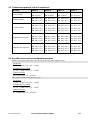
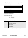
5.3 Possible cross sections and tightening torques
Inputs L1(2), L2(5), L3(8), N(11), I1(1-3), I2(4-6), I3(7-9), power supply (13-14)
Single wire
1 x 0,5 ... 6.0mm
2
or 2 x 0,5 ... 2.5mm
2
Multiwire with end splices
1 x 0,5 ... 4.0mm
2
or 2 x 0,5 ... 2.5mm
2
Tightening torque
0.5…0.6Nm resp. 4.42…5.31 lbf in
I/O's, relays, RS485 connector (A, B, C/X)
Single wire
1 x 0.5 ... 2.5mm
2
or 2 x 0.5 ... 1.0mm
2
Multiwire with end splices
1 x 0.5 ... 2.5mm
2
or 2 x 0.5 ... 1.5mm
2
Tightening torque
0.5…0.6Nm resp. 4.42…5.31 lbf in

PM 1000162 000 09 Device handbook SINEAX AM3000 10/86
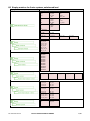
5.4 Inputs
All voltage measurement inputs must originate at circuit breakers or fuses rated 5 Amps or
less. This does not apply to the neutral connector. You have to provide a method for
manually removing power from the device, such as a clearly labeled circuit breaker or a
fused disconnect switch.
When using voltage transformers you have to ensure that their secondary connections
never will be short-circuited.
No fuse may be connected upstream of the current measurement inputs!
When using current transformers their secondary connectors must be short-circuited
during installation and before removing the device. Never open the secondary circuit under
load.
The connection of the inputs depends on the configured system (connection type).

PM 1000162 000 09 Device handbook SINEAX AM3000 11/86
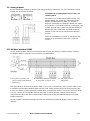
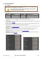
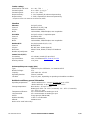
Single-phase AC mains
Direct connection
If current I
N
or voltage U
NE
does not need to be
measured, connection of IN resp. PE can be
omitted.
With current transformer
If current I
N
does not need to be measured, the
corresponding transformer can be omitted.
If voltage U
NE
does not need to be measured,
connection of PE can be omitted.
With current and voltage transformer
If current I
N
or voltage U
NE
does not need to be
measured, the corresponding transformers can
be omitted.
L1 L2 L3
N
I1
31
I2
4
I3
97
IN
PE
6
10 12 16
11 2 5 8
L1
N
5 A
(UL listed)
PE
L1 L2
L3
N
I1
31
I2
4
I3
97
IN
PE
6
10 12 16
11 2 5 8
L1
N
5 A
(
UL listed)
K
k
L
l
K
k
L
l
PE
L1
N
K
k
L
l
L1 L2 L3
N
I1
31
I2
4
I3
97
IN
PE
6
10 12 16
11 2 5 8
5 A
(UL listed)
PE
K
k
L
l
u
U
v
V
u
U
v
V

PM 1000162 000 09 Device handbook SINEAX AM3000 12/86
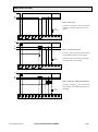
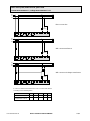
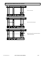
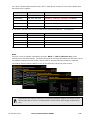
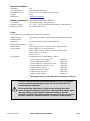
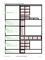
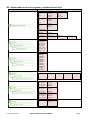
Three wire system, balanced load, phase shift
current measurement: L1, voltage measurement: L1-L2
Direct connection
With current transformer
With current and voltage transformers
In case of current measurement via L2 or L3 connect the device
according to the following table:
Terminals 1 3 2 5 8
Current meas. via L2 I2(k) I2(l) L2 L3 -
Current meas. via L3 I3(k) I3(l) L3 L1 -
L1 L2 L3
N
I1
31
I2
4
I3
97
IN
PE
6
10 12 16
11 2 5 8
L1
L2
L3
5 A
(
UL listed)
L1 L2 L3
N
I1
31
I2
4
I3
97
IN
PE
6
10 12 16
11 2 5 8
L1
L2
L3
K
k
L
l
5 A
(UL listed)
L
1 L2 L
3
N
I
1
3
1
I2
4
I3
97
IN
PE
6
10
12 16
11
2 5 8
K
k
L
l
5 A
(
UL listed)
u
U
v
V

PM 1000162 000 09 Device handbook SINEAX AM3000 13/86
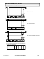
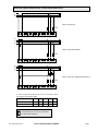
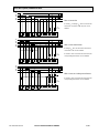
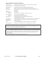
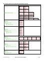
Three wire system, balanced load, phase shift
current measurement: L1, voltage measurement: L2-L3
Direct connection
With current transformer
With current and voltage transformers
In case of current measurement via L2 or L3 connect the device
according to the following table:
Terminals 1 3 2 5 8
Current meas. via L2 I2(k) I2(l) - L3 L1
Current meas. via L3 I3(k) I3(l) - L1 L2
L1 L2 L3
N
I1
31
I2
4
I3
9
7
IN
PE
6
10 12 16
11 2 5 8
L1
L2
L3
5 A
(UL listed)
L1 L2 L3
N
I1
31
I2
4
I3
97
IN
PE
6
10 12 16
11 2 5 8
L1
L2
L3
K
k
L
l
5 A
(UL listed)
L
1 L2 L
3
N
I1
31
I2
4
I3
9
7
IN
PE
6
10
12 16
11 2
5 8
K
k
L
l
5 A
(
UL listed)
u
U
v
V

PM 1000162 000 09 Device handbook SINEAX AM3000 14/86
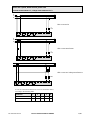
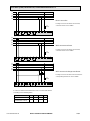
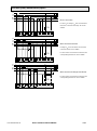
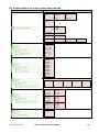
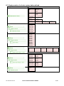
Three wire system, balanced load, phase shift
current measurement: L1, voltage measurement: L3-L1
Direct connection
With current transformer
With current and voltage transformers
In case of current measurement via L2 or L3 connect the device
according to the following table:
Terminals 1 3 2 5 8
Current meas. via L2
I2(k)
I2(l)
L2 - L1
Current meas. via L3
I3(k) I3(l) L3 - L2
L1 L2 L3
N
I1
31
I2
4
I3
97
IN
PE
6
10 12 16
11 2 5 8
L1
L2
L3
5 A
(UL listed
)
L1 L2 L3
N
I1
31
I2
4
I3
97
IN
PE
6
10 12 16
11 2 5 8
L1
L2
L3
K
k
L
l
5 A
(UL listed)
L1 L2 L3
N
I1
31
I2
4
I3
97
IN
PE
6
10 12 16
11 2 5 8
L1
L2
L3
K
k
L
l
5 A
(UL listed)
v
V
u
U

PM 1000162 000 09 Device handbook SINEAX AM3000 15/86
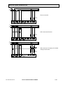
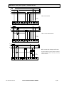
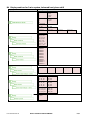
Three wire system, balanced load, current measurement via L1
Direct connection
With current transformer
With current and voltage transformers
In case of current measurement via L2 or L3 connect the device
according to the following table:
Terminals 1 3 2 5 8
Current meas. via L2
I2(k)
I2(l)
L2 L3 L1
Current meas. via L3
I3(k) I3(l) L3 L1 L2
By rotating the voltage connections the
measurements U12, U23 and U31 will be
assigned interchanged!
L1 L
2
L3
N
I1
31
I2
4
I3
97
IN
PE
6
10 12 16
11 2 5 8
L1
L2
L3
5 A
(
UL listed)
L1
L2
L3
N
I1
31
I2
4
I3
97
IN
PE
6
10 12 16
11 2
5 8
L1
L2
L3
K
k
L
l
5 A
(UL listed
)
L1 L2 L3
N
I1
31
I2
4
I3
97
IN
PE
6
10 12 16
11 2 5 8
L1
L2
L3
K
k
L
l
5 A
(UL listed)
u
U
v
V
u
U
v
V

PM 1000162 000 09 Device handbook SINEAX AM3000 16/86
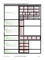
Four wire system, balanced load, current measurement via L1
Direct connection
If voltage U
NE
does not need to be measured,
connection of PE can be omitted.
With current transformer
If voltage U
NE
does not need to be measured,
connection of PE can be omitted.
With current and voltage transformer
If voltage U
NE
does not need to be measured, the
corresponding transformer can be omitted.
In case of current measurement via L2 or L3 connect the device
according to the following table:
Terminals 1 3 2 11
Current meas. via L2
I2(k)
I2(l)
L2 N
Current meas. via L3
I3(k) I3(l) L3 N
L1 L2 L3
N
I1
31
I2
4
I3
97
IN
PE
6
10 12 16
11 2 5 8
L1
L2
L
3
N
5 A
(UL listed)
PE
L
1
L2
L3
N
I1
31
I
2
4
I
3
9
7
IN
PE
6
10
12
16
11
2
5
8
L
1
L
2
L
3
N
K
k
L
l
5 A
(
UL listed
)
PE
L1 L2 L3
N
I1
31
I2
4
I3
97
IN
PE
6
10 12 16
11 2 5 8
L1
L2
L3
N
K
k
L
l
5 A
(UL listed)
u
U
v
V
u
U
v
V
PE

PM 1000162 000 09 Device handbook SINEAX AM3000 17/86
Three wire system, unbalanced load
Direct connection
With current transformers
With current and 3 single-pole isolated
voltage transformers
L1 L
2
L3
N
I1
31
I2
4
I3
97
IN
PE
6
10 12 16
11 2 5 8
L1
L2
L3
5 A
(UL listed
)
L1 L2 L3
N
I1
31
I2
4
I3
97
IN
PE
6
10 12 16
11 2 5 8
L1
L2
L3
K
k
L
l
K
k
L
l
K
k
L
l
5 A
(UL listed)
L1 L2 L3
N
I1
31
I2
4
I3
97
IN
PE
6
10 12 16
11 2 5 8
L1
L2
L3
K
k
L
l
K
k
L
l
K
k
L
l
L1 L2 L3
N
I1
31
I2
4
I3
97
IN
6
10 12 16
11 2 5 8
x
u
X
U
X
U
X
U
x
u
x
u
5 A
(UL listed)

PM 1000162 000 09 Device handbook SINEAX AM3000 18/86
Three wire system, unbalanced load, Aron connection
Direct connection
With current transformers
With current and 3 single-pole isolated
voltage transformers
L1 L2 L3
N
I1
31
I2
4
I3
97
IN
PE
6
10
12 16
11 2 5 8
L1
L2
L3
5 A
(
UL listed
)
L1 L2 L3
N
I1
31
I2
4
I3
97
IN
PE
6
10 12 16
11 2 5 8
L1
L2
L3
K
k
L
l
K
k
L
l
5 A
(UL listed)
L1 L2 L3
N
I1
31
I2
4
I3
97
IN
PE
6
10 12 16
11 2 5 8
L1
L2
L3
K
k
L
l
K
k
L
l
x
u
X
U
X
U
X
U
x
u
x
u
5 A
(UL listed)

PM 1000162 000 09 Device handbook SINEAX AM3000 19/86
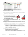
Four wire system, unbalanced load
Direct connection
If current I
N
or voltage U
NE
does not need to be
measured, connection of IN resp. PE can be
omitted.
With current transformer
If voltage U
NE
does not need to be measured,
connection of PE can be omitted.
If current I
N
does not need to be measured, the
corresponding transformer can be omitted.
With current and voltage transformer
If current I
N
does not need to be measured, the
corresponding transformer can be omitted.
L1 L2 L3
N
I
1
31
I2
4
I3
97
IN
PE
6
10 12 16
11 2 5 8
L1
L2
L3
N
5 A
(UL listed)
PE
L
1
L2 L3
N
I1
31
I
2
4
I
3
97
IN
PE
6
10
12 16
11
2 5 8
L
1
L2
L3
N
K
k
L
l
K
k
L
l
K
k
L
l
5 A
(
UL listed)
PE
K
k
L
l
L1 L2 L3
N
I1
31
I2
4
I3
97
IN
PE
6
10 12 16
11 2 5 8
L1
L2
L3
N
K
k
L
l
K
k
L
l
K
k
L
l
x
u
X
U
X
U
X
U
x
u
x
u
5 A
(UL listed)
K
k
L
l

PM 1000162 000 09 Device handbook SINEAX AM3000 20/86
Four wire system, unbalanced load, Open-Y
Direct connection
If current I
N
or voltage U
NE
does not need to be
measured, connection of IN resp. PE can be
omitted.
With current transformer
If voltage U
NE
does not need to be measured,
connection of PE can be omitted.
If current I
N
does not need to be measured, the
corresponding transformer can be omitted.
With current and voltage transformer
If current I
N
does not need to be measured, the
corresponding transformer can be omitted.
L
1 L2 L3
N
I
1
3
1
I2
4
I3
97
IN
PE
6
10
12 16
11 2 5 8
L1
L
2
L3
N
5 A
(UL listed)
PE
N
L
1
L2
L3
N
I1
31
I
2
4
I
3
97
IN
PE
6
10
12 16
11 2
5 8
L1
L
2
L
3
N
5 A
(UL listed
)
PE
N
K
k
L
l
K
k
L
l
K
k
L
l
K
k
L
l
L1 L2 L3
N
I1
31
I2
4
I3
97
IN
PE
6
10 12 16
11 2 5 8
L1
L
2
L3
N
5 A
(UL listed)
N
K
k
L
l
K
k
L
l
K
k
L
l
K
k
L
l
x
u
X
U
X
U
x
u
La page est en cours de chargement...
La page est en cours de chargement...
La page est en cours de chargement...
La page est en cours de chargement...
La page est en cours de chargement...
La page est en cours de chargement...
La page est en cours de chargement...
La page est en cours de chargement...
La page est en cours de chargement...
La page est en cours de chargement...
La page est en cours de chargement...
La page est en cours de chargement...
La page est en cours de chargement...
La page est en cours de chargement...
La page est en cours de chargement...
La page est en cours de chargement...
La page est en cours de chargement...
La page est en cours de chargement...
La page est en cours de chargement...
La page est en cours de chargement...
La page est en cours de chargement...
La page est en cours de chargement...
La page est en cours de chargement...
La page est en cours de chargement...
La page est en cours de chargement...
La page est en cours de chargement...
La page est en cours de chargement...
La page est en cours de chargement...
La page est en cours de chargement...
La page est en cours de chargement...
La page est en cours de chargement...
La page est en cours de chargement...
La page est en cours de chargement...
La page est en cours de chargement...
La page est en cours de chargement...
La page est en cours de chargement...
La page est en cours de chargement...
La page est en cours de chargement...
La page est en cours de chargement...
La page est en cours de chargement...
La page est en cours de chargement...
La page est en cours de chargement...
La page est en cours de chargement...
La page est en cours de chargement...
La page est en cours de chargement...
La page est en cours de chargement...
La page est en cours de chargement...
La page est en cours de chargement...
La page est en cours de chargement...
La page est en cours de chargement...
La page est en cours de chargement...
La page est en cours de chargement...
La page est en cours de chargement...
La page est en cours de chargement...
La page est en cours de chargement...
La page est en cours de chargement...
La page est en cours de chargement...
La page est en cours de chargement...
La page est en cours de chargement...
La page est en cours de chargement...
La page est en cours de chargement...
La page est en cours de chargement...
La page est en cours de chargement...
La page est en cours de chargement...
La page est en cours de chargement...
La page est en cours de chargement...
-
 1
1
-
 2
2
-
 3
3
-
 4
4
-
 5
5
-
 6
6
-
 7
7
-
 8
8
-
 9
9
-
 10
10
-
 11
11
-
 12
12
-
 13
13
-
 14
14
-
 15
15
-
 16
16
-
 17
17
-
 18
18
-
 19
19
-
 20
20
-
 21
21
-
 22
22
-
 23
23
-
 24
24
-
 25
25
-
 26
26
-
 27
27
-
 28
28
-
 29
29
-
 30
30
-
 31
31
-
 32
32
-
 33
33
-
 34
34
-
 35
35
-
 36
36
-
 37
37
-
 38
38
-
 39
39
-
 40
40
-
 41
41
-
 42
42
-
 43
43
-
 44
44
-
 45
45
-
 46
46
-
 47
47
-
 48
48
-
 49
49
-
 50
50
-
 51
51
-
 52
52
-
 53
53
-
 54
54
-
 55
55
-
 56
56
-
 57
57
-
 58
58
-
 59
59
-
 60
60
-
 61
61
-
 62
62
-
 63
63
-
 64
64
-
 65
65
-
 66
66
-
 67
67
-
 68
68
-
 69
69
-
 70
70
-
 71
71
-
 72
72
-
 73
73
-
 74
74
-
 75
75
-
 76
76
-
 77
77
-
 78
78
-
 79
79
-
 80
80
-
 81
81
-
 82
82
-
 83
83
-
 84
84
-
 85
85
-
 86
86


Gossen MetraWatt SINEAX AM3000 Mode d'emploi
- Catégorie
- Mesure, test
- Taper
- Mode d'emploi
dans d''autres langues
Documents connexes
-
Gossen MetraWatt SINEAX A210 Mode d'emploi
-
-
-
-
-
-
Camille Bauer SINEAX CAM Guide d'installation
-
-
-
Gossen MetraWatt METRAHIT ENERGY Manuel utilisateur
Autres documents
-
 Hach IO9000 User Instructions
-
Amprobe DM-II PLUS Power Quality Recorder Manuel utilisateur
-
Leviton 6X318-KIT Le manuel du propriétaire
-
Eurotherm 392 Le manuel du propriétaire
-
Eaton 66061 Fiche technique
-
 Panamax MB1000 Manuel utilisateur
-
 Setra Systems Power Meter (Multi-Load) Mode d'emploi
-
Fronius TS 5kA-3 Mode d'emploi
-
 Rotronic PCDS Manuel utilisateur
-
Elster GASLAB Q2 Mode d'emploi


