Samsung WF350ANP/XAA Troubleshooting guide
- Catégorie
- Machines à laver
- Taper
- Troubleshooting guide
Ce manuel convient également à

1
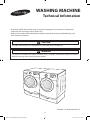
WASHING MACHINE
Technical Information
Code No. : DC68-02834A-04_EN
• Due to possibility of personal injury or property damage, always contact an authorized
technician for servicing or repair of this unit.
• Refer to Service Manual for detailed installation, operating, testing, troubleshooting, and
disassembly instructions.
All safety information must be followed as provided in Service Manual.
CAUTION
To avoid risk of electrical shock, personal injury or death; disconnect power to washer
before servicing, unless testing requires power.
WARNING
Techsheet-WF350AN-02834A-04_EN.indd 1 2012-01-20 �� 1:33:33

ALIGNMENT AND ADJUSTMENTS
2
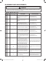
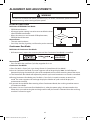
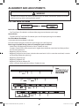
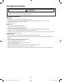
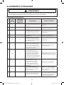
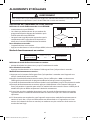
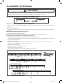
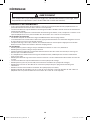
GENERAL ERROR FUNCTION
NO
Error
Code
Diagnostic Code
Error Image
Description Corrective Action
1 nd 1
The water level fails to drop below
the Reset Water Level within 15
minutes.
Go to “ Will Not Drain”
Troubleshooting Section.
2 LO 2
Door fails to Unlock After 7
attempts.
Go to “ Will Not Unlock”
Troubleshooting Section.
3 nF 3
When the lling Continues for
more than 40 minutes or there is no
change of water level for 6 minutes.
Go to “ No Water Fill”
Troubleshooting Section.
4 FL 4
Door fails to lock after 7 attempts.
Go to “ Will Not Lock”
Troubleshooting Section.
5 LE 8
A water level lower than the Reset
water level (25.6Khz) is detected for
5 seconds during the Wash/Rinse
cycle.
Go to “No Water Fill”
Troubleshooting Section.
6 LE 8
Water Level Sensor Trouble. (When
the input signal from the water level
sensor is out of range, the unit will
send out beeping sounds and halts
the cycle.)
Go to “No Water Fill”
Troubleshooting Section
7 OE E
A fault is detected in the water level
sensor. Data (frequency) shows
the water level is at or above the
overow water level. (When this
condition is detected, the machine
will automatically starts draining
water until the water level falls
below the overow water level)
First check to see that all of water
valves are not stuck. If water valves
are OK, check water level sensor.
8 dc 10
Unbalance or cabinet bump is
detected during nal spin, which
prevents the drum from spinning
over 150 rpm. (Never exceeds 150
RPM due to unbalanced load)
Go to “Wet Clothes” Troubleshooting
Section.
9 E2 15
Jammed Key.(When key input
signals are coming out for more
than 30 seconds, it is regarded as
a jam.)
Check all of keys. If A key is sensed
to be pressed, all keys will do not
respond.
10 dL 18
Door is detected as open when the
motor is operating.
Check for loose wire connections. Go
to “Quick Test Mode” and then do Door
lock/Unlock Test and Motor Test.
To avoid risk of electrical shock, personal injury or death; disconnect power to washer
before servicing, unless testing requires power.
WARNING
Techsheet-WF350AN-02834A-04_EN.indd 2 2012-01-20 �� 1:33:33

ALIGNMENT AND ADJUSTMENTS
3
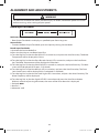
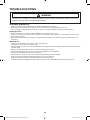
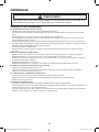
NO
error
code
Diagnostic Code
Error Image
Description Corrective Action
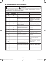
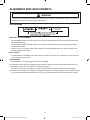
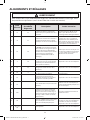
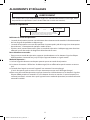
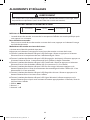
11 ds 22
Door is detected as open while it is
trying to lock the door.
Go to “Quick Test Mode” and then
do Door Lock/Unlock Test
12 tE 29
Abnormal high/low temperature or
resistance (Thermal sensor or PBA
resistance).
Go to “ Board Input Test” and check
Water Temperature. Check loose
or pinched wires. Replace PCB or
thermistor.
13
3E
2E
MICOM is attempting to drive the motor
but is not getting any response signals
from the hall sensor. Visual check shows
motor is not running. (Locked, Defective
Hall Sensor or Overload)
Evaluate wire harness for loose or
unhooked connections. Go to “
Quick Test Mode” and test Motor.
14
Sr 34
System Relay (Main Relay) Failure.
(PCB does not notice the relay
operation when there should be.)
Replace PCB.
15
Hr 36
Heater Relay Failure (No Heater
Relay Check Signal)
Replace PCB
16
nF1 5
The hot/cold water hose connection
is not correct.
Please connect the hot/cold water
hose connection correctly.
17 2E -
Voltage for motor control bus is
over or under specied limit.
Replace PCB
18 7E -
Silver Care Kit (PCB) Failure.
Check PCB ,Main PCB & Wire-
harness
19 suds -
Suds is detected during the washing
session. (“SUdS” is not an error. If the
washer is in suds period, “SUdS” will
light up instead of remaining time.)
Guide a user to reduce amount of
detergent usage.
20 AE
-
Communication error between SUB
PBA and MAIN PBA
Check Main PBA, SUB PBA & Wire-
harness. Replace PCB
21
SF1,
SF2,
SF3
-
System Error Replace PCB
To avoid risk of electrical shock, personal injury or death; disconnect power to washer
before servicing, unless testing requires power.
WARNING
Techsheet-WF350AN-02834A-04_EN.indd 3 2012-01-20 �� 1:33:33

ALIGNMENT AND ADJUSTMENTS
4
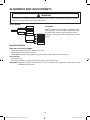
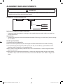
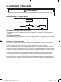
TEST MODE
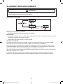
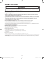
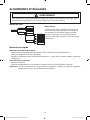
Test Mode:
Each Test Mode for the Squall is as follows in the
coming pages. The test modes indicated by the
red arrows are modes unable to get an access
once the washing cycle has started due to safety
resons.
Quick Test Mode
Denition of Quick Test Mode:
- Check operation of all LED’s (Verify faulty LED).
- Check model and software version.
- Check dierent operating modes (e.g. water valve, motor, door, drain pump, etc.).
How to Enter:
- Plug in the unit.
- Press Soil Level Key + Signal Key and Power Key at the same Time.
Important. Once test mode is performed, all data including the diagnostic code saved in the
EEPROM will be erased.
To avoid risk of electrical shock, personal injury or death; disconnect power to washer
before servicing, unless testing requires power.
WARNING
Special Test Mode
Power Off State
Quick Test Mode
EEPROM Clear
Mode
Continuous Cycle
Mode
Service Mode
Demo Mode
Quick Spin Test Mode
Cycle Count Check Mode
S/W Version Check Mode
Fast Time Down Test Mode
Board Input Test Mode
Diagnostic Code
CheckMode
Power On State
(Normal User Mode)
Techsheet-WF350AN-02834A-04_EN.indd 4 2012-01-20 �� 1:33:34

ALIGNMENT AND ADJUSTMENTS
5
Quick Test Mode:
1. All LED’s light up and it sends out Beep Sound when it
enters into the Quick Test Mode. (Including 7-Segment)
2. Displays software version for a sec and Clear EEprom. (Ex. If
S/W Version is 49, 7-Segment will display E149)
3. When the version is displayed, turn the Jog-Dial so that
the version disappears. Press the following keys to test the
various components.
- Temp Key : Water Valve Test
- Spin Key : Door Lock/Unlock Test
- Soil Key : Water/Steam Heater Test(Steam Models)
Water Test(Non-Steam Models)
- Signal Key : Drain Pump Test
To avoid risk of electrical shock, personal injury or death; disconnect power to washer
before servicing, unless testing requires power.
WARNING
Techsheet-WF350AN-02834A-04_EN.indd 5 2012-01-20 �� 1:33:34

ALIGNMENT AND ADJUSTMENTS
6
EEPROM Clear Check
Denition of EEPROM Clear Mode:
- EEPROM initialization.
- All course/option settings are to be reset to default values
after EEPROM initialization.
- When Service arises and it needs PCB replacement,
EEPROM should be reset.
How to Enter:
- The unit needs to be on.
-
Press Delay Start Key, Signal Key, and Power Key at the same time.
Continuous Run Mode
Denition of Continuous Run Mode:
- Will continuously repeat the current cycle until the Continuous Run Mode is cancelled.
How to Enter:
- Press Pre Wash Key and Pure Cycle Key together for 3 sec.
Continuous Run Mode:
1. Press
Pre Wash + Pure Cycle 3 sec
during Power On State (Normal User Mode) .
2.
Once in Continuous Run Mode, The seven segments will no longer display “0000” and will alternate
between displaying the number of cycles of the completed course and the remaining time of the course.
3. The Continuous Run Mode will repeat the previous cycle until continuous run mode is cancelled.
4.
During Continuous Run Mode, press Pre Wash + Pure Cycle 3 seconds to return to normal user
mode. The seven segments will no longer display the number of cycles and will display the
maintenance time only.
5. If you exit Service Mode after entering it from Continuous Mode, the washing machine returns
to Continuous Mode.
6. If power is lost in Continuous Run Mode (that is, when the power plug is disconnected or the
Power key is pressed turning the washing machine o), the mode is released when the washing
machine is turned on again.
To avoid risk of electrical shock, personal injury or death; disconnect power to washer
before servicing, unless testing requires power.
WARNING
Techsheet-WF350AN-02834A-04_EN.indd 6 2012-01-20 �� 1:33:34

ALIGNMENT AND ADJUSTMENTS
7
Service Mode
Denition of Service Mode:
- Service Mode enables service technicians to verify the operation of the washing machine and
do troubleshooting.
- Service Mode can be entered during all washing cycle without interrupting the cycle except
some of test modes.
- Various tests can be done with Service Mode. So, troubleshooting can be done based on the
resulting diagnostic codes.
How to Enter:
- To enter the Service Mode, press the Signal and Delay Start Keys for 3 seconds or until the unit
sends out beeping sounds.
Service Mode:
1. The washer must be on to go into the Service Mode.
2. The motor speed will be displayed when started (It displays 0 when the motor does not spin).
3. The present state of the machine will not be changed.
(i.e., the current cycle in progress will not be interrupted and only the display will change)
4. To exit Service Mode, press Signal and Delay Start Keys for 3 second again, or Power Key.If no key
is operated during Service Mode for 5 minutes, the machine will return to normal user mode.
To avoid risk of electrical shock, personal injury or death; disconnect power to washer
before servicing, unless testing requires power.
WARNING
Techsheet-WF350AN-02834A-04_EN.indd 7 2012-01-20 �� 1:33:34

ALIGNMENT AND ADJUSTMENTS
8
Quick Spin Test Mode
Denition of Quick Spin Test Mode:
- Quick Spin Test Mode is to do Spin Check. (High RPM)
How to Enter:
- During Service Mode, press the Dealy Start and Pre Wash Keys for 3 seconds to enter Quick Spin
Test Mode. (Same for all Frontier 2 models.)
- Cannot enter once the washing cycle has started.
Quick Spin Test Mode:
As it enters into the Quick Spin Test Mode, it starts spinning and reaches to its maximum RPM.
Once the Spin speed reaches the maximum RPM, the speed drops immediately.
To hold Quick Spin Test Mode (entering Hold Speed Mode), press the Start/Pause button. If the
Start/Pause button is pressed during Quick Spin Test Mode, it will stop accelerating and hold its
spinning speed for 10 minutes before going back to Quick Spin Test Mode.
Also, to cancel the hold and allow Quick Spin Test Mode to continue, press the Dealy Start and Pre
Wash Keys together for 3 seconds.
If you hold down the Dealy Start and Pre Wash keys for three (3) seconds when the washing
machine is not in Hold Speed Mode, Quick Spin Mode is exited and Service Mode is restored.
To avoid risk of electrical shock, personal injury or death; disconnect power to washer
before servicing, unless testing requires power.
WARNING
Techsheet-WF350AN-02834A-04_EN.indd 8 2012-01-20 �� 1:33:35

ALIGNMENT AND ADJUSTMENTS
9
Cycle Count Check Mode
Denition of Cycle Count Check Mode:
- Cycle Count Check Mode is to tally up the number of washings.
How to Enter:
- To enter the Cycle Count Check Mode, press the Signal Key during Service Mode.
Cycle Count Check Mode:
1. Activate the Service Mode in advance.
2. When the Signal key is pressed, the total number of washings will light up and a signal LED will
glow.
3. The maximum number of cycles will be 9999.
The counter will roll over to 0 and start counting again after 9999.
4. The counting will be carried out at the end of the normal cycle.
(For normal and Continuous Run cycles, the count is carried out at the end of the cycles.
5. To exit the Cycle Count Check Mode, press the “Signal” key again.
S/W Version Check Mode
Denition of S/W Version Check Mode:
- S/W Version Check Mode is to bring up S/W Version information.
How to Enter:
- To enter the S/W Version Check Mode, press the Soil Level Key during Service Mode.
S/W Version Check Mode:
1. Activate the Service Mode in advance.
2. Press the Soil Level Key to bring up its software Version
EX) Generate AE49 at Version 49 (AE is Micom code, 49 is it’s software version)
3. To exit the S/W Version Check Mode, press the Soil Level S/W once again.
Then, it returns to the Service Mode with motor RPM illuminating.
To avoid risk of electrical shock, personal injury or death; disconnect power to washer
before servicing, unless testing requires power.
WARNING
Techsheet-WF350AN-02834A-04_EN.indd 9 2012-01-20 �� 1:33:35

ALIGNMENT AND ADJUSTMENTS
10
Fast Time Down Test Mode
Denition of Fast Time Down Test Mode:
- Fast Time Down Test Mode is to forward the program to the next cycle stage.
How to Enter:
- To enter the Fast Time Down Test Mode, press the Temp key during Service Mode.
Fast Time Down Test Mode:
1. Activate the Service Mode in advance.
2. To forward the program to the next cycle stage, press the Temp key.
Each stage is located at key points of a complete cycle as follows:
- End of Each Fill (Beginning of Wash or Rinse Tumble Session)
Caution: Check if the current water level is higher than the Reset water level and then perform
the Fast time down test.
- Beginning of Drain Session
- Beginning of Spin Session (Here, it checks the water level. So, if it is over the reset level, it carries
out draining before the spinning.)
- Beginning of Fill Session
- Beginning of Bleach Fill
- Beginning of Fabric Softener Fill
- Every 3 minutes during Wash and Rinse Tumble Session
To avoid risk of electrical shock, personal injury or death; disconnect power to washer
before servicing, unless testing requires power.
WARNING
Techsheet-WF350AN-02834A-04_EN.indd 10 2012-01-20 �� 1:33:35

ALIGNMENT AND ADJUSTMENTS
11
Board Input Test Mode
Denition of Board Input Test Mode:
- Board Input Test Mode is to displays a specied input after a key press.
How to Enter:
- To enter the Board Input Test Mode, press the Spin Key during Service Mode.
Board Input Test Mode:
1. Activate the Service Mode rst.
2. Press the Spin Key to start Board Input Test.
3. Turn the Jog-Dial so that the Pre Wash LED is turned on, and press the Start/Pause key. The Water
Temperature will be displayed in Celsius.
4. Turn the Jog-Dial so that the Extra Rinse(or Steam) LED is turned on, and press the Start/Pause
key. The Water Temperature will be displayed in Fahrenheit.
5. Turn the Jog-Dial so that the Cold/Cold LED is turned on, and press the Start/Pause key. The door
status will be displayed (OP if open, CL if closed).
6. Turn the Jog-Dial so that the No Spin LED is turned on, and press the Start/Pause key. The Door
Lock Switch status will be displayed (UL if unlocked, LO if locked).
7. Turn the Jog-Dial so that the Soil Level Light LED is turned on, and press the Start/Pause key. The
Water Frequency will be displayed.
8. Turn the Jog Dial so that the Signal O LED is turned on and press the Start/Pause button.
Within 3 seconds of pressing the button, the status of the Silver Nano kit is displayed.
1. Delayed: 0000
2. Normal: ---
3. Abnormal: ㅂE
To avoid risk of electrical shock, personal injury or death; disconnect power to washer
before servicing, unless testing requires power.
WARNING
Techsheet-WF350AN-02834A-04_EN.indd 11 2012-01-20 �� 1:33:36

ALIGNMENT AND ADJUSTMENTS
12
Diagnostic Code Check Mode
Denition of Diagnostic Code Check Mode:
- Diagnostic Code Check Mode is to bring up the stored diagnostic codes (refere nce codes for
service technicians).
How to Enter:
- To enter the Diagnostic Code Check Mode with code “d” ashing, press the Pure Cycle key during
Service Mode.
Board Input Test Mode:
1. Activate the Service Mode rst.
2. Press the “Pure Cycle key” key to start Diagnostic Code Check Mode with Code “d” ashing.
3. To cycle through the diagnostic codes (d1,d2,d3~d9), turn the Rotary Cycle Selector in one
direction (either Clockwise or Counterclockwise).
4. Now, when turning the Rotary Selector Key in the same direction, it shows diagnostic codes
from the latest (d1).
5. When turning it in the opposite direction, it shows the diagnostic codes in the reverse order.
Ex) When it stops at d5 and turns backward, it shows from d4 down to “d”. Refer to Diagnostic
Code.
To avoid risk of electrical shock, personal injury or death; disconnect power to washer
before servicing, unless testing requires power.
WARNING
Service Mode
Pure Cycle
Start/Pause
Pressing
Signal
Diagnostic Code
Cycle No.
Before making Code
Cycle Count
Techsheet-WF350AN-02834A-04_EN.indd 12 2012-01-20 �� 1:33:36

ALIGNMENT AND ADJUSTMENTS
13
Demo Mode
- Demo mode is entered when the Delay Start + Signal + Spin buttons are held down for ve (5)
seconds simultaneously in the power on state.
- When entering Demo mode, the buzzer rings three (3) times and “- - - -” is displayed on the 7
segment display and all other LEDs are turned o. (Initial Demo mode)
- Demo mode consists of WASH, SPIN and LED modes.
- If the Temp button is pressed during the initial Demo mode, “WASH” blinks on the 7 segment
display and the washing machine enters WASH mode.
- If the Start/Pause button is pressed in WASH mode, the door is locked (Door Lock) and the motor
rotates left and right at 45 RPM in a 7 sec on and 3-sec o cycle.
- WASH mode continues up to ve (5) minutes once started. After the ve (5) minutes have
elapsed, “- - - -” is displayed on the 7 segment display and the initial Demo mode is maintained.
- If the Start/Pause button is pressed during a WASH mode operation, “- - - -” is displayed on the 7
segment display and the initial Demo mode is maintained.
- If the Spin button is pressed in the initial Demo mode, “Spin” blinks on the 7 segment display
and the washing machine enters SPIN mode.
- If the Start/Pause button is pressed in the SPIN mode, the door is locked (Door Lock) and a spin
is operated at 1150 RPM. When the speed reaches 0 RPM, the No Spin, Low, Medium, High, and
Extra High LEDs are turned on.
- During a spin operation, the No Spin LED turns on when the speed is lower than 400 RPM. The
Low LED turns on between 400 RPM and 800 RPM. The Medium LED turns on between 800 RPM
and 1000 RPM. The High LED turns on at higher than 1000 RPM.
- SPIN mode continues up to four (4) minutes once started. After the four (4) minutes have
elapsed, “- - - -” is displayed on the 7 segment display and the initial Demo mode is maintained.
- If the Start/Pause button is pressed during a SPIN mode operation, “- - - -” is displayed on the 7
segment display and the initial Demo mode is maintained.
- If the Pure Cycle button is pressed during the initial Demo mode, “LED” is displayed on the 7
segment display and the washing machine enters LED mode.
- If the Start/Pause button is pressed in LED mode, all LEDs are turned on. The LED mode
continues up to thirty (30) seconds once started. After the thirty (30) seconds have elapsed, “- - -
-” is displayed on the 7 segment display and the initial Demo mode is entered.
- If the Start/Pause button is pressed during an LED mode operation, “- - - -” is displayed on the 7
segment display and the initial Demo mode is entered.
To avoid risk of electrical shock, personal injury or death; disconnect power to washer
before servicing, unless testing requires power.
WARNING
Techsheet-WF350AN-02834A-04_EN.indd 13 2012-01-20 �� 1:33:36

14
TROUBLE DIAGNOSIS
- As the micom wash machine is congured of the complicate structure, there might be the
service call.
Below information is prepared for exact trouble diagnosis and suitable repair guide.
Caution for the Repair and Replacement
Please follow below instruction for the trouble diagnosis and parts replacement.
1) As some electronic components are damaged by the charged static electricity from the resin
part of machine or the human body, prepare the human body earth or remove the potential
dierence of the human body and machine by contacting the power supply plug when the
work contacting to PCB is executed.
2) Since AC120V is applied to the triac T1 and T2 on P.C.B, the electric shock may occur by touching
and be careful that the strong and weak electricity are mixed.
3) As the P.C.B assembly is designed for no trouble, do not replace the P.C.B assembly by the wrong
diagnosis and follow the procedure of the trouble diagnosis when the micom is not operated
normally.
TROUBLE SHOOTING
To avoid risk of electrical shock, personal injury or death; disconnect power to washer
before servicing, unless testing requires power.
WARNING
Techsheet-WF350AN-02834A-04_EN.indd 14 2012-01-20 �� 1:33:36

15
TROUBLE DIAGNOSIS
Will Not Start
• Plug the unit into the wall outlet. Check for proper voltage.
• Check fuse or reset circuit breaker.
• Push any key to turn on the washer and press the Start/Pause key to run the washer.
• Close door and push the Start/Pause key to run the washer.
• Check if washer is in a pause, soak or suds process. Wait briey and it may start. (If the washer is in suds
period, Suds will light up instead of remaining time.)
• Check for restricted drain system. (If there is electrical problem in drain system, “nd” error will occur after 15
minutes.)
• Check Water Supply.
• Check the line or water valve screen lter.
• Check if PCB connectors are assembled properly.
• Check if CN2 terminals on PCB are in good condition. (Refer to PCB Connector Check.)
• Replace PCB.
Leaking
• Make sure inlet hose connections are not leaking. Check for rubber gasket damage due to over tightening.
• Check standpipe for leak. Wrap a dry rag around the standpipe opening.
If rag becomes wet, leak is fault of home plumbing.
Be sure the standpipe is capable of accepting the ow of water from the washer.
• Make sure end of drain hose is correctly inserted and secured to drain standpipe.
• Check internal hose connections (ll, drain systems, dispenser hoses & clamps).
• Check rubber boot. Remove, reposition and reinstall, if necessary.
• Check for possible kinked dispenser to outer tub hose. Hot water pressurization may force door open.
No Tumble
• Start normal cycle with an empty machine and allow a ll to check tumble.
• Perform Quick Spin Test. (Before test, make sure that the tumbler is empty.)
• Check for loose connections at Machine Control Board, Pressure Switch, Motor, Tach Harness and Motor
Control. (Refer to the component testing procedure)
• Check motor windings resistance.
CN5 pins 1 & 3 = 11.6ohms ±7%,
Pins 1 & 2 = 11.6ohms ±7%,
Pins 2 & 3 = 11.6 ohms ±7%
• Faulty Main Control Board.
• Faulty motor.
Will Not Spin
• Make sure to close the door completely.
• Check for water left inside the washer. If so, go to “Will Not Drain”.
• Perform Quick Test Mode or Quick Spin Test. Does the washer spin? (Before the test, empty the unit inside.)
If it doesn’t tumble after the above, change PCB. When the problem persists, change the motor.
• Perform Quick Test Mode or Quick Spin Test. Does the washer spin? If it does, Check Possible unbalanced
load scenario in normal mode.
• Check for loose connections at PCB, Water Level Sensor, Motor, Hall Sensor Wire Harness. (CN7,CN5,CN6)
(Refer to the Component Testing Procedure.)
• Check motor windings resistance. (CN5 Pin1&3 = 11.6 ohms (at ±7% 20°C/68°F),
Pin1&2 = 11.6ohms (at ±7% 20°C),
Pin2&3 = 11.6 ohms (at ±7% 20°C))
TROUBLE SHOOTING
To avoid risk of electrical shock, personal injury or death; disconnect power to washer
before servicing, unless testing requires power.
WARNING
Techsheet-WF350AN-02834A-04_EN.indd 15 2012-01-20 �� 1:33:36

16
TROUBLE DIAGNOSIS
No Water Fill
• Perform Quick Test Mode. Check all of Water Valves visually.
(Pre Wash Valve, Cold Water Valve, Bleach Water Valve, Softener dispenses using Cold & Bleach Water Valve,
and Hot Water Valve.)
• Check if water taps are turned on fully.
• Check Water Valves and Water Level Sensor (Refer to PCB Connector Check)
• Check if there is any kink in inlet hoses.
• Check if inlet screens are clogged up.
• Check if water has enough pressure. If so, nd out its contributors.
• Check if there is any frozen area in the unit (Drain Hose, etc)
• Measure the resistance of Water Valve Coil.
(It should read 1.18K ohms. Check Pin#1 of CN2 and PIN#1,2,7,8,9 of CN3)
• Check Pressure S/W and PCB for loose connections. (Refer to PCB Connector Check.)
Tub Full of Suds
• Go to “Will Not Drain” and “Will Not Spin” and check the draining.
• Check PCB and Drain Pump for any loose wire connection.
• Perform Quick Test Mode or Board Output Test to drain.
• Use HE (High-Eciency) or low sudsing detergent specially formulated for front load washers.
• Reduce the amount of detergent for that specic load size and soil level. Keep in mind that towel creates
more suds generally.
• Reduce the amount of detergent when water is soft, or laundry is small or lightly soiled.
• Do one more washing cycle with cold water and a table spoon of salt without detergent.
TROUBLE SHOOTING
To avoid risk of electrical shock, personal injury or death; disconnect power to washer
before servicing, unless testing requires power.
WARNING
Techsheet-WF350AN-02834A-04_EN.indd 16 2012-01-20 �� 1:33:36

17
TROUBLE DIAGNOSIS
Wet Clothes
• Unbalance due to not enough load. Put additional load.
•
Due to excessive suds by using general detergent. Use HE (High-Eciency) or reduce its quantity.
• Low Spin Speed or Drain Only was selected.
• Go to “ Will Not Spin”.
Will Not Lock
• Door is not aligned or closed properly.
• Perform Quick Test Mode. Check Door Lock.
Check the output voltage of Door Lock Coil.
If it reads 120V, change Door Lock Switch, and if not, change PCB. (Refer to PCB Connector Check.)
• Read Lock Switch and PCB (CN3). (Refer to PCB Connector Check.)
• Try Door Lock and check for 120V to Door Lock Connector. If 120V present, change Main Control Board and
if not, change Door Lock switch.
Will Not Unlock
• Check if the door is being pushed out, which may keep it from unlocking.
• Door locks itself when the water level is too high. Opening door will result in water draining from door
opening.
• Check the following with Board Input Test Mode.
Water Level (frequency): Over 23.80 KHz.
If so, refer to “Will Not Drain”.
Temperature (Inside Drum): Higher than 60ºC/140ºF.
If so, wait until it drops.
When everything is normal, check PCB connectors and Door Lock Switch.
• Drain manually after removing the plastic drain hose holder.
• Display shows “LO”. Turn o and on the unit. If “LO” keeps illuminating, check PCB and Door Lock Switch.
TROUBLE SHOOTING
To avoid risk of electrical shock, personal injury or death; disconnect power to washer
before servicing, unless testing requires power.
WARNING
Techsheet-WF350AN-02834A-04_EN.indd 17 2012-01-20 �� 1:33:36

18
TROUBLE DIAGNOSIS
• Read Lock Switch and PCB (CN2 & CN3). (Refer to PCB Connector Check.)
• Perform Quick Test Mode. Check Door Lock. Check the output voltage of Door Lock Coil.
If it reads 120V, change Door Lock Switch, and if not, change PCB. (Refer to PCB Connector Check.)
No Key Operation
• Option and Function buttons respond dierently according to each cycle.
• Child Lock is being activated. To exit, hold down Soil Level Key and Signal Key simultaneously until it sends
out a beeping sound.
• When “End“ illuminates on the display, only Power button works. Press Power button and make new cycle
selections.
Will Not Drain
• Check for any kink on the drain hose. If any, straight it out.
• Check for any restriction in the drain hose.
• Close the door and press the Start/Pause Button. For safety reasons, the washer does not tumble or spin with
the door open.
• When it is freezing outside, check if it is frozen inside the drain hose.
• Check if the water level signal input is correct. Go to Board Input Test Mode.
• Go to Quick Test Mode and do Drain Pump Test.
• Check if there is any twist in the hose (the one between Tub and Drain Pump).
• Check if it reads AC 120V at the pump when a spin cycle is selected.
• Read the winding resistance of the pump motor. (14.2±7% Ohms)
• Check the pump at CN3(PIN3) on PCB. It should read AC 110~120V. (Refer to PCB Connector Check)
TROUBLE SHOOTING
To avoid risk of electrical shock, personal injury or death; disconnect power to washer
before servicing, unless testing requires power.
WARNING
Techsheet-WF350AN-02834A-04_EN.indd 18 2012-01-20 �� 1:33:37

19
TROUBLE DIAGNOSIS
Wrong Water Temperature
• Check if both of the water taps are fully open.
• Make sure the domestic water heater is set to deliver water lower than 120°F (49°C) hot water at the tap.
Also check water heater capacity and recovery rate.
• If the water heater is located far from the washer, screw out the hot water tap and let its water pass until you
get hot water.
• Too Hot/Too Cold: Reduced amount of water is supplied while PCB controls the inux to regulate the actual
temperature of the water in the tub. This may appear to be signicantly hotter/colder than expected.
• Check if the temperature selection is correct.
• Disconnect inlet hoses from the Water Valve and remove any residue in the inlet screens.
Noisy and/or Vibration/Walking
• Check if the washer is leveled and the lock nuts are tightened up on the bottom plate.
• Check if all of the shipping bolts and spacers are removed from the back panel.
•
Check if load is big enough and there is no unbalance.If there is not enough load, put in a few towels to balance it.
• Check if the motor is fastened enough.
• Remove various trouble contributors (such as dust coat on the oor).
Rubber Feet Leaving Marks on Floor
• Use a pencil eraser to remove mark.
• Walk washer into location, do not drag.
Additive Cups Full of Water
• Small amount of water in bottom of additive cups is normal.
• Remove and wash Dispenser Tray, removable Cup, and Rinse Cap.
• Level washer.
Buttons do not Respond
• Option and Function buttons respond dierently according to each cycle.
• Child Lock feature has been selected. To disable feature press and hold Temp and Spin simultaneously until a
beep is heard.
• When display shows “End”, only the Power button will function. Press Power and make new cycle selections.
TROUBLE SHOOTING
To avoid risk of electrical shock, personal injury or death; disconnect power to washer
before servicing, unless testing requires power.
WARNING
Techsheet-WF350AN-02834A-04_EN.indd 19 2012-01-20 �� 1:33:37

20
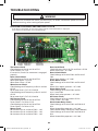
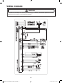
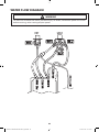
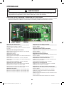
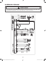
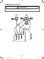
Thermistor Check
Check Voltage at Pin #4 and #5 of CN7
Tester Check = DC 2.5V
If it reads 5V, Check if its connector is engaged
properly
Door Switch Check
Check Voltage at Pin #1 and #3 of CN4
When Door Open = DC 25V
When Door Close = DC 0V
Water Sensor Check
Check Voltage and Frequency at Pin #5 and #6
of CN7
Reset water level = DC2.5V, 25.8KHz
Check Voltage and Frequency at Pin #5 and #7
of CN7
Reset water level = DC2.5V, 25.8KHz
Hall Sensor Check
Check Voltage at Pin #4 and #2 of CN6
Tester Check = DC 0V or 3.75V
Check Voltage at Pin #4 and #3 of CN6
Tester Check = DC 0V or 3.75V
Motor Check
Resistance at Pin #1 and #2 of CN5 = 12Ω
Resistance at Pin #1 and #3 of CN5 = 12Ω
Resistance at Pin #2 and #3 of CN5 = 12Ω
Door Lock Check
Check Voltage at Pin #3 of CN2 and Pin #1 of CN3
When Door Lock = AC 120V
Door Unlock Check
Check Voltage at Pin #3 of CN2 and Pin #2 of
CN3
When Door Unlock = AC 120V
Drain Motor Check
Check Voltage at Pin #3 of CN2 and Pin #3 of
CN3
When Drain Motor operates = AC 120V
Water Valve Check
Check Voltage at Pin #3 of CN2 and Pin
#1,2,7,8,9 of CN3
When each valve operates = AC 120V
AC Power Check
Check Voltage at Pin #1 and #2 of CN2
Tester Check = AC 120V
Wash Heater Relay Check
Check Voltage at Pin #3 of CN2 and PIN #2 of
RY3
When Heater Relay operates = AC 120V
Steam Heater Relay Check(Only Steam Models)
Check Voltage at Pin #3 of CN2 and PIN #2 of
RY4
When Heater Relay operates = AC 120V
PROBLEM CHECKING AND METHOD OF PCB
- If you plug in the power cord and turn Power S/W on, memorized data is displayed.
If any data is not displayed, check the followings.
TROUBLE SHOOTING
To avoid risk of electrical shock, personal injury or death; disconnect power to washer
before servicing, unless testing requires power.
WARNING
Techsheet-WF350AN-02834A-04_EN.indd 20 2012-01-20 �� 1:33:37
La page charge ...
La page charge ...
La page charge ...
La page charge ...
La page charge ...
La page charge ...
La page charge ...
La page charge ...
La page charge ...
La page charge ...
La page charge ...
La page charge ...
La page charge ...
La page charge ...
La page charge ...
La page charge ...
La page charge ...
La page charge ...
La page charge ...
La page charge ...
La page charge ...
La page charge ...
La page charge ...
La page charge ...
La page charge ...
La page charge ...
La page charge ...
La page charge ...
-
 1
1
-
 2
2
-
 3
3
-
 4
4
-
 5
5
-
 6
6
-
 7
7
-
 8
8
-
 9
9
-
 10
10
-
 11
11
-
 12
12
-
 13
13
-
 14
14
-
 15
15
-
 16
16
-
 17
17
-
 18
18
-
 19
19
-
 20
20
-
 21
21
-
 22
22
-
 23
23
-
 24
24
-
 25
25
-
 26
26
-
 27
27
-
 28
28
-
 29
29
-
 30
30
-
 31
31
-
 32
32
-
 33
33
-
 34
34
-
 35
35
-
 36
36
-
 37
37
-
 38
38
-
 39
39
-
 40
40
-
 41
41
-
 42
42
-
 43
43
-
 44
44
-
 45
45
-
 46
46
-
 47
47
-
 48
48


Samsung WF350ANP/XAA Troubleshooting guide
- Catégorie
- Machines à laver
- Taper
- Troubleshooting guide
- Ce manuel convient également à
dans d''autres langues
Documents connexes
-
Samsung WF42H5200AP/A2 Manuel utilisateur
-
-
-
-
Samsung WF393BTPAWR Manuel utilisateur
-
-
-
-
-
Samsung WF340ANG/XAC Manuel utilisateur