Klein Tools BC503C Manuel utilisateur
- Catégorie
- Outils électroportatifs
- Taper
- Manuel utilisateur

BC503C
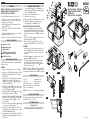
WORK TRAY ASSEMBLY – INSTRUCTIONS
ENSAMBLE DE BANDEJA DE TRABAJO –
INSTRUCCIONES
PLATEAU DE TRAVAIL – INSTRUCTIONS
8
3 54
6 7
FIG. A FIG. B
FIG. C
ENGLISH
WARNINGS
READ ALL INSTRUCTIONS. FAILURE TO FOLLOW THESE
WARNINGS AND INSTRUCTIONS MAY RESULT IN
SERIOUS BODILY INJURY OR DEATH.
•
Check all hardware is tightened before each use.
•
Inspect before each use: make sure all hardware is
fully tightened. Do not use if there are signs of cracks,
breakage or any other damage.
•
The Work Tray is rated to hold a maximum of 40 lbs.
(18 kg) Do NOT exceed.
•
Do NOT step or stand on the Work Tray. It is NOT for
human support.
•
Risk of Dropped Objects: Do not hang or tether tools or
equipment from the Work Tray.
•
Always remove and stow your Work Tray before driving.
SYMBOLS ON PRODUCT
Warning or Caution
Weight Rating: 40 lbs
Read Instructions
No Tether Point: Not for Fall Arrest,
Not for Dropped Object Prevention
Do Not Step or Stand
ASSEMBLY INSTRUCTIONS
Read these instructions carefully before operating and keep
for future reference.
ASSEMBLY
1. Assemble 1 Arm
2
into an arm slot in the Tray
1
.
2. Align the holes of the Arm
2
with the holes in the Tray
1
.
3. Add an M8 Lock Washer
7
to a M6 × 10 mm Long
Barrel Nut
4
.
4. From the inside of the Tray
1
, insert the Long Barrel
Nut
4
into one of the upper 2 holes
2
. Press it
through the Arm
2
, Work Tray
1
and Arm
2
on the
outside of the Work Tray
1
.
5. Insert a M6 × 16 mm Bolt
3
from the outside of the
Work Tray
1
through the Arm
2
so it meets up with
the Barrel Nut
3
and hand-tighten.
6. Repeat with another Long Barrel Nut
4
, Lock Washer
7
and Bolt
3
at the other upper hole location.
7. Add an M8 Lock Washer
7
and M8 Flat Washer
6
to
an M6 × 10 mm Short Barrel Nut
5
. From the inside
of the Tray
1
, insert the Barrel
5
into one of the
lower 4 holes
2
.
8. Press the sleeve through the Work Tray
1
and Arm
2
on the outside of the Work Tray
1
.
9. Insert a M6 × 16 mm Bolt
3
from the outside of the
Work Tray
1
through the Arm
2
so it meets up with
the Barrel Nut
4
and hand-tighten.
10. Repeat with three more Short Barrels
5
, Lock Washers
7
, Flat Washers
6
, and Bolts
3
at the 3 other lower
hole locations.
11. Use the M6 Hex Key
8
on the corresponding sleeve,
and while holding the Bolt
3
in the pocket, tighten the
sleeve to the Bolt
3
until snug
12. Repeat on the other five hardware sets.
13. Repeat on the second Arm
2
.
14. Make sure all fasteners are fully tightened before using.
15. Install Foam Pads
9
on to the underside of the
Arms
2
(optional, see FOAM PADS section).
INSTALLATION ONTO BUCKET WORK CENTER
•
Lower assembled Work Tray at an angle so that the
opening in the Arms
2
wrap around the Bucket Work
Center wall, with the top of the Arm
2
reaching inside
the bucket and the bottom of the Arm
2
on the outside
(Fig A).
•
Hook the lips of both Arms
2
under the bottom of the
top rail inside the bucket (Fig B).
•
Rotate the Work Tray
1
so that the bottom of the
Arms
2
rest against the outside of the bucket. (FIG C).
FOAM PADS
•
Foam Pads
9
can be used to minimize movement of
the Work Tray
1
along the rail system wall that may
occur when positioning your bucket or accidentally
bumping it.
•
If the Work Tray
1
moves around too easily, consider
adding the pads
9
to the assembly.
•
The Foam Pads
9
are designed to sit between each
Arm
2
and the top of the rail system wall. Simply
remove the adhesive liner from each Pad
9
and press
firmly at the locations shown.
NOTE: The Foam Pads
9
are not designed to slide along
the wall so repositioning the Work Tray
1
will require it
to be lifted and rotated away from the wall before sliding.
CLEANING AND STORAGE
Clean the product with mild soap and water only. Rinse
and wipe dry. Store in a cool place.
ASSEMBLY INSTRUCTIONS
PARTS INCLUDED
1. Tray (×1) 6.M8 Flat Washer (×9)
2. Arms (×2) 7.M8 Lock Washer (×13)
3. M6 × 16 mm Bolt (×13) 8.M6 Hex Key (×1)
4. M6 × 10 mm Long Barrel (×5) 9.Foam Pads (×2)
5. M6 × 10 mm Short Barrel (×9)
NOTE:
Parts in 3, 4, 5, 6, 7, 8 may include extra hardware.
CUSTOMER SERVICE
KLEIN TOOLS, INC.
450 Bond Street, Lincolnshire, IL 60069 1-800-553-4676
[email protected] www.kleintools.com
6
2
3
7
4
5
1
9
1390738 Rev 06/23 A

1390738 Rev 06/23 A
ADVERTENCIAS
LEA TODAS LAS INSTRUCCIONES. NO SEGUIR ESTAS
ADVERTENCIAS E INSTRUCCIONES PUEDE CAUSAR
LESIONES PERSONALES GRAVES O INCLUSO LA MUERTE.
•
Antes de cada uso, verifique que todo el hardware esté ajustado.
•
Examine antes de cada uso: asegúrese de que todo el
hardware esté completamente ajustado. No lo use si hay
señales de grietas, roturas o cualquier otro daño.
•
La bandeja de trabajo tiene una capacidad máxima
de40lb(18kg). NO la supere.
•
NO pise ni se pare en la bandeja de trabajo. NO sirve para
sostener personas.
•
Riesgo de caída de objetos: no cuelgue ni ate herramientas
oequipos de la bandeja de trabajo.
•
Retire y guarde siempre la bandeja de trabajo antes
deconducir.
SÍMBOLOS EN EL PRODUCTO
Advertencia o precaución
Peso nominal: 40lb
Lea las instrucciones
Sin puntos de sujeción para atar cuerdas:
noestádiseñado para detención de caídas; no está
diseñado para prevención de caída de objetos
No lo pise ni se pare encima
INSTRUCCIONES DE ENSAMBLAJE
Lea estas instrucciones con atención antes de usar la batería
yconsérvelas para consultarlas en el futuro.
ENSAMBLAJE
1. Ensamble 1brazo
2
en una ranura para brazos de
labandeja
1
.
2. Alinee los orificios del brazo
2
con los orificios de
labandeja
1
.
3. Agregue una arandela de seguridad M8
7
a una tuerca
cilíndrica larga M6 × 10mm
4
.
4. Desde el interior de la bandeja
1
, inserte la tuerca cilíndrica
larga
4
en uno de los 2orificios superiores
2
. Presiónela a
través del brazo
2
, la bandeja de trabajo
1
y el brazo
2
en
el exterior de la bandeja de trabajo
1
.
5. Inserte un perno M6 × 16mm
3
desde el exterior de la
bandeja de trabajo
1
a través del brazo
2
para que se
crucecon la tuerca cilíndrica
3
y ajuste a mano.
6. Repita con otra tuerca cilíndrica larga
4
, arandela
de seguridad
7
y perno
3
en la otra ubicación del
orificiosuperior.
7. Agregue una arandela de seguridad M8
7
y una arandela
plana M8
6
a una tuerca cilíndrica corta M6 × 10mm
5
.
Desde el interior de la bandeja
1
, inserte el cilindro
5
en
uno de los 4orificios inferiores
2
.
8. Presione el manguito a través de la bandeja de trabajo
1
y el
brazo
2
en el exterior de la bandeja de trabajo
1
.
9. Inserte un perno M6 × 16mm
3
desde el exterior de la
bandeja de trabajo
1
a través del brazo
2
para que se
encuentre con la tuerca cilíndrica
4
y ajuste a mano.
10. Repita con trescilindros cortos adicionales
5
, arandelas de
seguridad
7
, arandelas planas
6
y pernos
3
en las otras
3ubicaciones de orificios inferiores.
11. Utilice la llave hexagonal M6
8
en el manguito correspondiente
y, mientras sujeta el perno
3
en el compartimiento, apriete el
manguito al perno
3
hasta que quede ajustado.
12. Repita con los otros cincojuegos de hardware.
13. Repita en el segundobrazo
2
.
14. Antes de usar, asegúrese de que todos los sujetadores estén
completamente ajustados.
15. Instale almohadillas de espuma
9
en la parte inferior de los
brazos
2
(opcional, consulte la sección ALMOHADILLAS
DEESPUMA).
INSTALACIÓN EN EL CENTRO DE LA CANASTILLA DE TRABAJO
•
Baje la bandeja de trabajo ensamblada en ángulo de modo
quela abertura en los brazos
2
envuelva la pared del
centrode la canastilla de trabajo, con la parte superior del
brazo
2
alcanzando el interior de la canastilla y la parte
inferior delbrazo
2
en el exterior (Fig. A).
•
Enganche los bordes de ambos brazos
2
que se encuentran
debajo de la parte inferior del riel superior dentro de la
canastilla (Fig. B).
•
Gire la bandeja de trabajo,
1
de modo que la parte inferior de los
brazos
2
descanse contra la parte exterior de la canastilla (Fig. C).
ALMOHADILLAS DE ESPUMA
•
Se pueden usar almohadillas de espuma
9
para minimizar el
movimiento de la bandeja de trabajo
1
a lo largo de la pared
del sistema de rieles, que podría producirse cuando se coloca
la canastilla o se golpea accidentalmente.
•
Si la bandeja de trabajo
1
se mueve con demasiada facilidad,
considere la posibilidad de agregar las almohadillas
9
al ensamble.
•
Las almohadillas de espuma
9
están diseñadas para colocarse
entre cada brazo
2
y la parte superior de la pared del sistema
de rieles. Simplemente retire el forro interior adhesivo de cada
almohadilla
9
y presione firmemente en las ubicaciones que
se muestran.
NOTA: las almohadillas de espuma
9
no están diseñadaspara
deslizarse a lo largo de la pared, por lo que para volver a
posicionar la bandeja de trabajo
1
será necesario que se levanten
yse giren para alejarlas de la pared antes de que se deslicen.
PIEZAS INCLUIDAS
1.
2.
3.
4.
5.
Bandeja (×1)
Brazos (×2)
Perno M6 × 16mm (×13)
Cilindro largo M6 × 10mm (×5)
Cilindro corto M6 × 10mm (×9)
6.
7.
8.
9.
Arandela plana M8 (×9)
Arandela de seguridad M8
(×13)
Llave hexagonal M6 (×1)
Almohadillas de espuma (×2)
NOTA:
las piezas de 3, 4, 5, 6, 7, 8 podrían incluir hardware adicional.
LIMPIEZA Y ALMACENAMIENTO
Limpie el producto únicamente con agua y jabón suave. Enjuague
y seque con un paño. Almacene en un lugar fresco.
SERVICIO AL CLIENTE
KLEIN TOOLS, INC.
450 Bond Street, Lincolnshire, IL 60069 1-800-553-4676
[email protected] www.kleintools.com
INSTRUCCIONES DE ENSAMBLAJE AVERTISSEMENTS
VEUILLEZ LIRE TOUTES LES INSTRUCTIONS. LEUR
NON-RESPECT RISQUE D’ENTRAÎNER DES BLESSURES
CORPORELLES GRAVES OU LA MORT.
•
Vérifiez que toutes les pièces sont bien serrées avant
chaqueutilisation.
•
Inspectez le produit avant chaque utilisation: toutes les
piècesdoivent être bien serrées. Ne l’utilisez pas s’il y a des
signes de fissures, de bris ou de tout autre dommage.
•
Le plateau de travail peut supporter un poids maximal
de18kg(40lb). NE DÉPASSEZ PAS cette limite.
•
NE MARCHEZ PAS et ne vous tenez pas debout sur le plateau
de travail. Ce produit N’EST PAS destiné à soutenir des humains.
•
Pour limiter les risques de chute d’objets, ne suspendez pas et
n’attachez pas des outils ou de l’équipement au plateau de travail.
•
Retirez et rangez toujours le plateau de travail avant de conduire.
SYMBOLES SUR LE PRODUIT
Avertissement ou mise en garde
Poids nominal: 40lb
Lire les instructions
Le produit ne comporte aucun point d’attache: produit non
conçu pour empêcher les chutes d’objets ou d’humains
Ne pas marcher ou se tenir debout sur le produit
INSTRUCTIONS D’ASSEMBLAGE
Lisez attentivement les instructions avant d’utiliser le produit et
conservez-les à des fins de référence.
ASSEMBLAGE
1. Insérez un support
2
dans l’une des fentes du plateau
1
.
2. Alignez les trous du support
2
avec les trous du plateau
1
.
3. Ajoutez une rondelle de blocageM8
7
à un écrou à baril
longM6 de 10mm
4
.
4. Depuis l’intérieur du plateau
1
, insérez l’écrou à baril
long
4
dans l’un des deux trous supérieurs
2
. Faites-le
passer à travers le support
2
, le plateau de travail
1
et le
support
2
vers l’extérieur du plateau de travail
1
.
5. Insérez un boulonM6 de 16mm
3
dans le support
2
depuis
l’extérieur du plateau de travail
1
, jusqu’à ce qu’il touche à
l’écrou à baril
3
, puis serrez-le à la main.
6. Répétez ces étapes avec un autre écrou à baril long
4
,
une rondelle de blocage
7
et un boulon
3
à l’autre
trousupérieur.
7. Ajoutez une rondelle de blocageM8
7
et une rondelle
plateM8
6
à un écrou à baril courtM6 de 10mm
5
.
Depuis l’intérieur du plateau
1
, insérez le baril
5
dans
l’undes quatre trous inférieurs
2
.
8. Faites passer le baril à travers le plateau de travail
1
et le
support
2
, depuis l’extérieur du plateau de travail
1
.
9. Insérez un boulon M6 de 16mm
3
dans le support
2
depuis
l’extérieur du plateau de travail
1
, jusqu’à ce qu’il touche à
l’écrou à baril
4
, puis serrez-le à la main.
10. Répétez ces étapes avec trois autres écrous à baril courts
5
,
rondelles de blocage
7
, rondelles plates
6
et boulons
3
aux
trois autres trous inférieurs.
11. Utilisez la clé hexagonaleM6
8
sur le baril correspondant
et, tout en maintenant le boulon
3
en place, serrez le baril
sur le boulon
3
jusqu’à ce qu’il soit bien ajusté.
12. Répétez cette étape pour les cinq autres ensembles de pièces.
13. Répétez toutes ces étapes pour le deuxième support
2
.
14. Assurez-vous que toutes les pièces de fixation sont bien
serrées avant d’utiliser le produit.
15. Installez les coussinets de mousse
9
sous les supports
2
(étape facultative, voir la section COUSSINETS DE MOUSSE).
INSTALLATION SUR LA STATION DE TRAVAIL SUR NACELLE
•
Inclinez le plateau de travail de manière à ce que chaque
support
2
entoure la paroi de la station de travail sur nacelle.
La partie supérieure du support
2
doit se trouver à l’intérieur de la
nacelle et la partie inférieure du support
2
, à l’extérieur (FIG.A).
•
Accrochez la bordure des deux supports
2
sous la bordure
supérieure à l’intérieur de la nacelle (FIG.B).
•
Faites pivoter le plateau de travail
1
de manière à ce que la
partie inférieure des supports
2
soit accotée contre l’extérieur
de la nacelle (FIG.C).
COUSSINETS DE MOUSSE
•
Les coussinets de mousse
9
peuvent être utilisés pour
minimiser le mouvement du plateau de travail
1
le long
du système de rail pour paroi qui peut se produire lorsque
vous positionnez votre nacelle ou lorsque vous la cognez
accidentellement.
•
Si le plateau de travail
1
bouge trop facilement, envisagez
d’ajouter les coussinets
9
pendant l’assemblage.
•
Les coussinets de mousse
9
sont conçus pour être placés
entre chaque support
2
et le haut du système de rail pour
paroi. Il suffit de retirer le revêtement adhésif de chaque
coussinet
9
et d’appuyer fermement aux endroits indiqués.
REMARQUE: Les coussinets de mousse
9
ne sont pas conçus
pour glisser le long de la paroi. Pour repositionner le plateau de
travail
1
, soulevez-le et inclinez-le pour l’éloigner de la paroi,
puis faites-le glisser.
PIÈCES COMPRISES
1.
2.
3.
4.
5.
Plateau (1)
Supports (2)
BoulonsM6 de 16mm (13)
Écrous à baril longsM6
de10mm (5)
Écrous à baril courtsM6
de10mm (9)
6.
7.
8.
9.
Rondelles platesM8 (9)
Rondelles de blocageM8 (13)
Clé hexagonaleM6 (1)
Coussinets de mousse (2)
REMARQUE:
Pour les pièces3, 4, 5, 6, 7 et 8, un nombre plus
élevé que celui indiqué pourrait être fourni.
NETTOYAGE ET RANGEMENT
Nettoyez le produit avec de l’eau et du savon doux uniquement.
Rincez-le et essuyez-le. Entreposez-le dans un endroit frais.
SERVICE À LA CLIENTÈLE
KLEIN TOOLS, INC.
450 Bond Street, Lincolnshire, IL 60069 1-800-553-4676
[email protected] www.kleintools.com
INSTRUCTIONS D’ASSEMBLAGE
FRANÇAISESPAÑOL
-
 1
1
-
 2
2


Klein Tools BC503C Manuel utilisateur
- Catégorie
- Outils électroportatifs
- Taper
- Manuel utilisateur
dans d''autres langues
- English: Klein Tools BC503C User manual
- español: Klein Tools BC503C Manual de usuario
Autres documents
-
Haier BrewMaster HBF205E Manuel utilisateur
-
-
Ryobi WS731 Mode d'emploi
-
Haier BrewMaster HBF05E Manuel utilisateur
-
Sears 183.91579 Manuel utilisateur
-
-
 Pit Boss PBCBG110010002 Mode d'emploi
-
Danby DKC052BSL2DB Le manuel du propriétaire
-
Igloo BK49BS Manuel utilisateur
