Maytag 23-11-2222N-001 Manuel utilisateur
- Catégorie
- Climatiseurs split-system
- Taper
- Manuel utilisateur

Room Air Conditioner
Acondicionador de Aire
Climatiseur
Dehumidifier
Deshumidificador
D6shumidificateur
Air Purifier
Purificaci6n de Aire
Epurateur d'air
Write down the model and
serial numbers
Use these numbers in any correspondence or
service calls concerning vour air conditioner. Keep
\ our store receipt.
Escriba los ndmeros del
modelo y de ia serie _/
Uti]ice estos numeros en cuaJquier
correspondencia o [[amada de servicio refereme a su acondicionador
de aire. Guarde el recibo de ]a tienda.
|nscrivez les num6ros de module et de
serie
Rappe]ez ces num6ros dans tout courrier ou appe] pour ntervention
concerna qt ]e c]imatiseur. Conserver ]e recu du magasin.
Model No.. Moflelo No.. N ° de modHe
7
Serial _o.. Nthnero de serif. N _ de sdrk
For additional questions please call:
866-NIAYTAG 1
D¢_td d _Ptllt'h¢_sd Pc'c']l_ fie hi dOIYlt)Hl, i)Htd d_7¢'ll¢Tt
@@@@@@@@@ @@@@@
@
e
@
@
@
Keep these instructions for future reference
@@ @

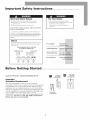
important Safety instructions o, oooo o 0 o o, oooo o
E|ectrica| Shock Hazard
1. Plug unit only into grounded electrical outlet,
2= Do not use an extension cord or plug adapter
with this unit.
3= Do not operate unit with front removed,
Failure to follow the above precautions could result in electrical
shock, fire or personal injury.
If the unit has a serial [)late rating of 115 volts and up to and
including 7.5 amps, the unit may be on a fuse or circuit breaker
with other devices. However, the maximum amps of all devices on that
fuse or circuit breaker cannot exceed the amps of the fuse or circuit
breaker.
Notice
Do not operate this unit without proper time delay circuit
protection, Refer to serial plate for proper power supply
requirements.
RECOMMENDED CIRCUIT WIRE SIZES
(As installed per building code)
PROTECTOR SIZE WIRE GAUGE
15 AMP #14 MINIMUM
20 AMP #12 MINIMUM
30 AMP #10 MINIMUM
ll5V 230V 230V 230V
I_A I_A 20A 30A
Foe' Your Safety:
" Do not store or use gasoline or other
flammable vapors and liquids in the vicinity
of this or any other appliance.
The fumes {-an create a fire hazard or
explosion,
Power Supply: t 15 V, 60HZ
AC Only 1-Phase
Outlet Requirement: :
Minimum Wire Size: #14
Use Copper
Circuit Protector
ll_l_l_l_l_l_l_l_l_l_l_l_l_l_l_l_l_l_l_l_l_l_l_l_l_l_l_l_l_l_l_l_l_l_l_l_l_l_l_l_l_l_l_l_l_l_l_l_l_l_l_l_l_l_l_l_l_l_l_l_l_l_l_l_l_l_l_:__¸_
Before Getting Started oooooo oooooo oooooo oooooo
important
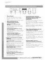
Grounding Requirements
Your unit will operate on any ]]5 volt, 3-pronged
(grounded), 60 Hz circuit, A separate line is not required, but
it is advisable not to overload the circuit with heavy duty
appliances such as washing machines, etc. For your safety,
this unit is equipped with a 3-pronged, grounding plug and
must be plugged into a properly grounded outlet (Figs. _ ,_ 2).
If your outlet is not of the proper type, it is your
responsibility to have the outlet and wiring changed to the
correct type. DO NOT CUT OFF THE THIRD (GROUNDING)
PRONG. DO NOT USE AN ADAPTER.
Grounded
three-prong
wall receptacle
Three-prong
grounding plug
Et
Single outlet
grounding
wall receptacle

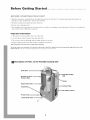
Before Getting Started oooo0 oo oooo0 oo oooo0 oo oooo0 oo
B S YT
Read the instruction manual before operating the unit for the first time. It contains important information on
operation, safety, maintenance, service and warranty.
Keep this instruction manual for future reference.
• Do not start a damaged unit.
• The assembly and connection of the unit must be carried out according to the instructions. If they are not followed
you run the risk of w-)iding the warranty.
important information
1. The power cord is located in the rear of the unit.
2. Do not allow contact between the unit and water.
3. Do not cover the air discharge and air intake louvers of the unit.
4. Proper venting of the air to the exterior is required at all times.
After turningoff thesystemwait at least 3 minutes before restarting it.
Theunit hascastersto easemovement. If it is necessaryto tilt the unit, it must first beemptied of water in the internal tank usingthedrain valve at the
bottom of the unit. (Seethesection When transporting the unit or Storing the unit for theseason.)
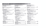
_'_ Description of Parts on the Portable Coo|ing Unit
Drain Hose
Upper Drain Valve
Serial Plate
Portable Cooling
Unit
Nozzle
Exhaust Tube
intake Louvers
Power Cord
Lower Drain Valve
2

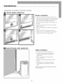
installation .o o0,oooo o0, o oo0 o oooo o0 oooo o0 o oo0 o0 o.
Window installation
1. Place the nozzle in the exhaust tube (Fig. 4a).
2. Open the window and place the window adapter
in the window, extending it to fit the width of
the window, close the window (Fig. 4b).
3. Secure the window adapter to the window sill
(Fig. 4c).
4. Insert the nozzle into the slot in the window
adapter (Fig. 4d).
5. Select a cooling mode; normal cool or high cool
(Fig. 6).
6. Adjust to the desired temperature setting.
7. Air direction can be adjusted using the handle
found on the top of the control panel.
Cooling Through a Door Application
Mobile Installation
1. Place the nozzle in the exhaust tube.
2. Open the door slightly and position the
nozzle between the door and the door
jamb (Fig. S).
3. Select a cooling mode; normal cool or
high cool (Fig. 6).
4. Adjust to the desired temperature setting
(Fig. 6).
S. Air direction can be adjusted using the
handle found on the top of the control
panel.
Important: Do not over-stretch the exhaust tube or make any
unnecessary bends in it.
3

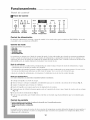
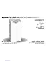
Control Pane| Disp|ay
_ _ i
@ @ @ @ @
fflGlt tOW fflGH LOW DEffUMIDIFY
COOLCOOLFAN FAR
DISPLAY
TIME_°C_°F O
TIMER/SET
@ @
START STOP
CLEAN DRAIN
FILTER WATER
Power Mode Display Time/ Timer Warning
Control Control Control Temperature Controls Lights
Controls
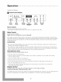
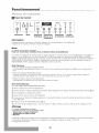
Power Control
The power control turns the unit on and off.
A green light will indicate that the unit is ON, if there is no light the unit if OFF.
Mode Control
The Mode Control has five settings:
High Cool, Low Cool, High Fan, Low Fan, Dehumidify
The settings are adjusted with the Mode Control button. A green light will indicate which setting is currently being
used. When either of the cooling modes is selected, the unit will circulate and cool the air. If either of the fan modes is
selected, the unit will only circulate the air. When the dehumidify setting is selected, the unit will remove moisture
and circulate the air.
Cooling Mode
* The unit cools and dehumidifies at the same time for more comfort. During the cooling mode condensed water is
released to the outside air through the nozzle.
, In conditions of extreme humidity the unit will accumulate condensed water in an internal tank. At that time the
drian water light will blink indicating that the tank must be emptied (see the section on Draining the Water, Page 6).
, Adjust cooling speed, thermostat and air deflection to suit your desired comfort level.
Dehumidification Mode
In this mode the unit reduces the ambient humidity in the room.
1. Place the nozzle in the exhaust tube.
2. Open the window and place the window adapter in the window, extending it to fit the width of the window.
Close the window (Fig. 4).
3. Secure the window adapter to the window sill.
4. Insert the nozzle into the slot in the window adapter.
S. Ensure that the upper drain valve is in the closed position and that the rubber plug is in place (Fig. 7 d).
6. Select the Dehumidifying mode (Fig. 6).
7. If the drain water light is blinking, indicating that the internal bucket is full, follow the recommended
water draining procedure (page 6).
Display Control
The display control is used to change the current display setting. There are three settings on the display:
Temperature/Fahrenheit, Temperature/Celsius, Timer
The display will return from the time setting to the Fahrenheit setting after the control has not been depressed for five
seconds. The temperature on the display is the set temperature. It is NOT the actual room temperature.
4

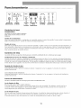
® @ @ @ @
itlGH LOW HIGH LOW DEHNIOIFY
COOLCOOLFAN FAN
TIMER/SET
@ @
CLEAN DRAIN
FILTER WATER
Power Mode Display Time/ Timer Warning
Control Control Control Temperature Controls Lights
Controls
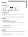
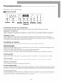
Time/Temperature Controls
These buttons are used to change the set temperature, the clock, start time, and stop time.
Temperature Change
Select either Fahrenheit or Celsius on the display by using the Display Control, then change the set temperature in
increments of 1° using the Time/Temperature.
Time Change
Select the time display with the Display Control and change the clock with the Time/Temperature controls. The time
will increase or decrease in one minute increments with each depression. If either the up or down buttons is held
down, the time will change continuously until the button is released. The AM and PM lights will change appropriately
with the clock.
Timer Controls
The Timer Controls can be used to set a time for the air conditioner to start as well as a time for the air conditioner to shut off.
Setting a Start/Stop Time
Depress the start or stop button.
The display will now show a time.
Use the Time/Temperature controls to set the desired start/stop time.
After reaching the desired start/stop time, release the Time/Temperature control button.
The timer will be set after no buttons have been depressed for five seconds. A light above the start and stop
buttons will indicate when the timer is activated.
Shutting the Timer Function OFF
if the Start function is set:
Depress the Start button for three seconds.
The light will go off and the start function is now deactivated.
if the Stop function is set:
Depress the Stop button for three seconds.
The light will go off and the stop function is now deactivated.
Warning Lights
These lights will come on when the air conditioner needs attention.
Clean Filter Light
This light indicates that the filter needs to be cleaned. The air conditioner will continue to run even when the light is
on. However, the filter should be cleaned as soon as possible after the light comes on. After cleaning the filter, press both
Time/Temperature controls simultaneously to reset the filter monitor.
Drain Water Light
This light indicates that the internal water bucket needs to be drained. The unit will not operate until the water has
been drained. See section 6 of the owners' manual for instructions on how to drain the water. The air conditioner
must be set to dehumidify when the water is drained.
5

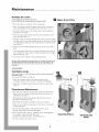
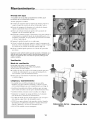
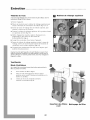
Draining the water
If the red light is lit, indicatingthat the internal
bucket is full, follow the recommended water draining procedure:
Upper Drain Valve
1. The unit must be switched to the off position.
2. Place a container under the upper drain valve and remove
the rubber plug from the upper drain valve (Fig. 7 a, b, c).
3. Insert the drain hose on the upper drain valve pointing it
towards the container.
4. Turn the upper drain valve from the closed position to the
open position (Fig. 7 b).
S. Turn the unit on, turn the thermostat to the warmest setting
and the switch to the dehmnidify position. The unit will turn
on, allowing the pump to run and drain the water from the
unit (Fig. 6).
6. When the water stops draining from the unit, turn off the
unit.
7. Close the upper drain valve, remove the drain hose, remove
the container of water, put the rubber plug back in the upper
drain valve (Fig. 7 d).
8. The unit can be turned to any operating mode.
Important: When changing the operating mode back to cooling do not forget to put
the rubber plug back in and turn the upper drain valve 900 to the right or to the
closed position. If this is not done the water will come out of the unit when it is
switched on.
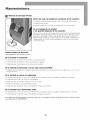
VENHLATION
Ventilation mode
In this mode the air is recycled to the interior of the room after passing through
the primary air filter.
1. To insert the filters see (Fig. 8).
2. Place the exhaust tube in the same position as the
cooling mode for either window or mobile installation.
3. Select the ventilation speed desired; normal or maximum
(Fig. 6).
Cleaning and Maintenance
* The unit has a primary air filter that must be cleaned with
water every two weeks and put back in the unit after it is
completely dry (Fig. 9).
* The purification filters should be replaced every year so
that the unit performs well.
* The fitting of the filters should be done as in (Fig. 8).
* Only one set of filters is required on the frame to maintain
cooling efficiency.
* The air discharge grille can be cleaned with a rag or
sponge, warm water and mild detergent.
* Never use hot water, bleach, gasoline, acids, cleaning fluid
or a brush to clean the unit. This will
damage the cabinet and the air discharge area.
* Do not wash the unit with a hose.
inserting Filters
6
Cleaning the
Filter

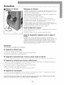
Nlaintenance o o ooo, o ooo, o ooo, o ooo, o ooo,
Before using at the start of a season
* Turn the unit on for four to five hours to dry it out.
* Clean the air filter.
* Clean the cabinet and air discharge areas if necessary.
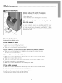
When transporting the unit or storing the unit
after the season
Drain excess water from the bottom tank by placing a pan under
the lower drain valve, remove the drain plug, and let the water
drain into the pan. When the water stops draining out, replace
the drain plug and remove the pan of water (Fig. 10). To drain
water using the upper drain valve refer to the section entitled
"Draining the Water".
Service instructions
Read carefully before calling for service
if the unit fails to start
¢" Make sure the unit is plugged into an outlet.
¢" Make sure the unit is not in the off position.
¢" Make sure the circuit breaker has not been tripped.
if the unit does not function and the drain water light is blinking
¢" Make sure the unit is standing level, if the light is still on, empty the internal water tank.
(See the section on Draining Water).
if the unit does not cool sufficiently
¢" Make sure the exhaust tube and nozzle fit correctly to each other and to the window adapter.
¢" Make sure the exhaust tube is not bent.
¢" Make sure the upper drain valve is in the closed position and both drain plugs are in place.
¢" Adjust the thermostat to a lower temperature.
¢" Make sure the exhaust tube and nozzle have nothing inside them.
if the
V"Make
V"Make
unit is too loud
sure the exhaust tube and nozzle fit correctly to each other and to the window mount.
sure the exhaust tube and nozzle have nothing inside.
Any other breakdown or repair must be carried out by an authorized servicer.
Tolocate your nearest Service Center, call 1-866-MAYTAG1.
7

For IVlodeis |nstailed
in North America - if Service
or Parts are Required
First, make the recommended checks. If it appears that
service or parts are still required, see your room air
conditioner warranty "How to Obtain Warranty Service or
Parts".
For NIodeis Installed
Outside North America
For room air conditioners purchased for use outside North
America, the manufacturer does not extend any warranty
either expressed or implied. Consult your local dealer for
any warranty terms extended by the importer in your
country.
Room Air Conditioner Warranty
(Within the 48 contiguous United States, state of Hawaii,
the District of Columbia, Puerto Rico and Canada)
FuR {FiveYear) Parts and Labor Warranty
During the five years after the date of original purchase,
Fedders Appliances will, through its authorized servicers
and free of charge to the owner or any subsequent user,
repair or replace any parts which are defective in material
or workmanship due to normal use. Ready access to the air
conditioner is the responsibility of the owner.
Note: in the event of any required parts replacement
within the period of this warranty, Fedders Appliances
replacement parts shall be used and will be warranted
only for the period remaining on the original warranty.
Exceptions
The above warranty does not cover failure to function
caused by damage to the unit while in your possession
(other than damage caused by defect or malfunction), or
by its improper installation, or by unreasonable use of the
unit, including without limitation, failure to provide
reasonable and necessary maintenance or to follow the
written Installation and Operating Instructions. If the unit
is put to commercial, business, rental, or other use or
application other than for consumer use, we make no
warranties, express or implied, including but not limited
to, any implied warranty of merchantability or fitness for
particular use or purpose.
THE REMEDIES PROVIDED FOR IN THE ABOVE EXPRESS
WARRANTY ARE THE SOLE AND EXCLUSIVE REMEDIES
THEREFOR, NO OTHER EXPRESS WARRANTIES ARE
MADE. ALL IMPLIED WARRANTIES, INCLUDING BUT NOT
LIMITED TO ANY IMPLIED WARRANTY OF
MERCHANTABILITY (JR FITNESS FOR A PARTICULAR USE
(JR PURPOSE, ARE LIMITED IN DURATION TO FIVE YEARS
FROM THE DATE OF ORI(;INAL PURCHASE. IN NO EVENT
SHALL Fedders Appliances BE LIABLE FOR INDIRECT,
INCIDENTAL, (JR CONSEQUENTIAL DAMAGES, EVEN IF
ADVISED IN ADVANCE OF THE POSSIBILITY OF SUCH
DAMAGES. NO WARRANTIES, EXPRESS (JR IMPLIED, ARE
MADE TO ANY BUYER UPON RESALE.
Some states do not allow limitations on how long an
implied warranty lasts or do not allow the exclusion or
limitation of incidental or consequential damages, so the
above limitations or exclusions may not apply to you.
This warranty gives you specific legal rights, and you may
also have other rights which may vary from state to state.
No warranties are made for units sold outside of the above
stated areas. Your distributor or final seller may provide a
warranty on units sold outside of these areas.
How to Obtain
Warranty Service or Parts
Service for your room air conditioner will be provided by
CareCo, a division of the manufacturer with authorized
independent CareCo servicers nationwide.
Note: Before calling for service, carefully read the
Installation and Operating Instructions booklet. Then if
you need service:
1. Call a CareCo authorized servicer and advise them of
model number, serial number, date of purchase and
nature of complaint. Service will be provided during
normal working hours. Contact your dealer for the
name of an authorized servicer if unknown to you.
2. If your dealer is unable to give you the name of a
servicer or if you need other assistance, call the
following toll-free number for the name of an
authorized servicer or authorized parts distributor:
1-866=NIAYTAG 1
or you may write:
CareCo, Service Department
415 W. Wabash Ave., P.O.Box 200
Effingham, [L 62401
Proof ot: Purchase Date
It is the responsibility of the consumer to establish the
original purchase date for warranty purposes. We
recommend that a bill of sale, cancelled check, or some
other appropriate payment record be kept for that
purpose.
8

|nstrucciones importantes de seguridad .0,o0,ooo.
Peiigro de
choque ei6ctrico
i • Enchtlfe la unidad ell till tol-nacOl?liente con conexidll a tiel'l?a.
2. No use un co]:d6n de extensi6n ni un adaptado]: de enchufe pal"a este unidad.
3. No haga funciona]" la unidad Sill la pa]:te h:ontal.
El no seguir las advertencias anteriores podrfa causar un cheque eldctrico o una lesi6n
personal.
Si en la placa de nQn_ero de serie hay una especiflcad6n de 115 voltios y hasta
7,5 amperios, la unidad puede compartil" un fusible o intel"ruptof de circuito con
otl"os dispositivos.
Sin embargo, el amperaje m_ximo de lodes los disposltivos e, ese fusible o
interrupter de ckcuito no puede exceder el amperaje del ft*sible o el interrupter de
circuito.
Pa]'a localiza]: la placa con el nflme]'o de se]ie aplicable a este modelo, yea la
p5gina poste]io]" de este manual.
Aviso
No opel'a]: esta unidad sin la p]:oteccidn adecuada de un (i]:cuito de tiempo
l:etardado, consulte la placa con el n6mel:o de sel:ie para los sulllinistl?OS de
COl'liente adecuados.
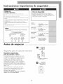
TAMAff¢OS QUE SE RECOMIENDAN PARA
LOS ALAMBREB DEL CIRCUITO
(Instalacidn tie acuerdo al c6digo tie construcci6n)
TAMAfVO DEL PROTECTOR GROSOR DEL CABLE
15 AMP #14 MINIMUM
20 AMP #12 MINIMUM
_0 AMP #10 MINIMUM
115V 230V 230V 230V
15A 15A 20A 30A
Para St= Seguridad:
*No guarde ni use gasolina u otros vapores o
liquidos inflamables cerca de esta unidad ni de
cualquier otto artefacto. Los vapores pueden crear
el riesgo de incendio o explosi6n.
Suministro
de corriente: 115V, 60HZ
Corriente alterna monofasica
solamente
Tomacorriente
que se requiere: De 3 patillas,
ripe conexi&_a tierra
125E 15Amp
Tamaffo mimmo
del alambre: No. 14 (A.W,G.) de 3 alambres
Use solamente
alambre de cobre
Protector dd
circuito: Fusible con retardo de
tiempo o h_terruptor de
cucuito de 15 Amp
Antes de empezar , ,,0,o0,oo.oo,0,o0,oo.oo,0,o0,oo.oo,0,o0,oo.oo,0,o0,oo
Receptdcu[o
de pared de Ires
patli[as con
conexi6n de tlerra
Requisitos importantes
para ia conexi6n a tien'a
Su unidad funcionar_ en cualquier circuit() de
115 voltios, de 3 patillas (con conexi6n a tierra)
y 60 Hz. No se requiem linea separada, pete es
aconsejable no sobrecargar el circuito con
artefactos que usan mucha corriente come
m_quinas de lavar ropa, etc. Para su seguridad,
esta unidad est_ equipada con un enchufe de 3
patillas de conexi6n a tierra y debe enchufarse en
un tomacorriente con la debida conexi6n a tierra
(figuras 1 y 2).
Si su tomacorriente no es del tipo adecuado,
usted tiene la responsabilidad de hacer que se
cambien tanto el tomacorriente come los
alambres al tipo adecuado.
NO CORTE LA TERCERA PATILLA DE CONEXION A
TIERRA. NO USE UN ADAPTADOR.
_hufe fe tres patillas con
conexi6n a tlerra
D Recept&cu[o
de pared con un s61o
tomacorrlente con
conexi6n a tlerra
9

Antes de empezar o 0 o ooo 0 o ooo0 0 o ooo0 0 o oo,o0 oo
* Antes de usar la unidad per la primera vez, lea el manual de instrucciones que contiene informaci6n importante
sobre su operaci6n, seguridad, mantenimiento, servicio y garantia.
* Guarde este manual de instrucciones para
consultarlo en el future.
* No encienda una unidad que est_ dafiada.
, E1 ensamblado y la conexi6n de la unidad debe llevarse a cabo de acuerdo alas instrucciones. Si no se siguen, usted
toma el riesgo de invalidar la garantia.
|nformaci6n importante
1. E1cord6n de electric|dad est_ situado en la parte posterior de la unidad.
2. No deje que la unidad est_ en contacto con el agua.
3. No cubra las rejillas de descarga y de toma de aire de la unidad.
4. En todo memento se necesita una salida adecuada del aire al exterior.
Despu& de apagar e/sistema, espere per Io menos 3 minutes antes de vo/ver a encenderlo.
ta unidad tiene ruedas para fadlitar el movimiento.
Si es necesario indinar/a, se debe primero radar el agua de! tanque interne, usando la valvula de drenaje en la parte inferior. Vea /a section
si se tmnsporta o ,_hrmcena la an|dad dumnte la estacidn.
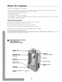
E! Descripci6n de las partes
de la unidad de
enfriamiento porter||
Unidad de
enfriamiento perI_til
Boquilla
Tube de escape
Rejillas de toma
de aire
10

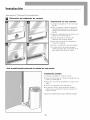
|nstalaci6n en una ventana
1, Coloque la boquilla en el tubo de escape
(fig, 4a),
2. Abra la ventana y coloque el adaptador,
extendi_ndolo para que se acomode a la
anchura de la ventana; cierre la ventana
(fig, 4b),
3, Asegure el adaptador para la ventana en el
alf_izar de la ventana (fig, 4c),
4. Inserte la boquilla en la ranura del
adaptador para ventana (fig, 4d).
5. Selecciones un modo de enfriamiento:
normal o alto (fig, 6).
6. Ajuste a la temperatura que desea (fig, 6).
7. La direcciOn del aire puede graduarse
usando la palanca que se encuentra en la
parte superior del panel de control,
Aire aco.dicio.ado poniendo la u.idad en u.a puerta
|nstalaci6n port_iti|
1, Coloque la boquilla en el tubo de escape.
2, Abra la puerta un poco y coloque la boquilla entre la
puerta y la )amba (fig, 5).
3, Seleccione un modo de enfriamiento: normal o alto
(Fig, 6).
4, Aiuste a la temperatura que desea (Fig, 6).
5. La direcci6n del aire puede graduarse usando la
palanca que se encuentra en la parte superior del
panel de control,
Importante: No extienda el tubo de escape ni Io dable sin necesidad.
11

Pane| de Control
J
Cont _! de
AJJmentacJ6n
• @ O O •
HIGH LOW HIGH LOW DEHtNIOIFY
COOLCOOLFAN FAN
DISPLAY
TIME;.°O.°F
TIMER/SET
0 0
START STOP
CLEAN DRAIN
FILTER WATER
de Moclo de Hora/ tie| Re|oj Acivertencia
Panta||a Temperatura
Control de alimentaci6n
E1 control de alimentaci6n enciende y apaga la unidad. La luz verde indica que la unidad estfi ENCENDIDA. Si no estfi
encendida la luz, la unidad estfi APAGADA.
Control de modo
El control de modo tiene cinco posiciones:
. Frio alto
. Frio bajo
. Venti|ador afro
. Ventilador bajo
. Deshumiclificaclor
Las posiciones se ajustan con el bot6n de control de modo. La luz verde indica que el modo se encuentra actualmente
en uso. Cuando se selecciona uno de los dos modos de enfriamiento, la unidad harfi circular el aire y lo enfriarfi. Si se
selecciona uno de los dos modos de ventilaci6n la unidad s61o harfi circular el aire. Cuando se selecciona la funci6n de
deshumidificaci6n, la unidad eliminarfi la humedad y harfi circular el aire.
Modo de enfriamiento
* Para mayor confort, la unidad enfria y deshmnedece al mismo tiempo. Durante el modo de enfriamiento, el agua
condensada pasa al exterior por medio de la boquilla.
* En condiciones de humedad extrema la unidad acumularfi el agua condensada en un tanque intemo. En este caso la
luz roja se encenderfi para indicar que se debe vaciar el tanque. Vea/a soccidn sobre Drenajo dol agua.
, Ajuste la velocidad de enfriamiento, el tennostato y la deflexidn de aire al nivel de confort deseada.
Modo para deshumedecer
En el modo de deshumedecer, ]a unidad reduce la humedad del ambiente en ]ahabitaci6n.
1. Coloque la boquilla en el tubo de escape.
2, Abra la ventana y coloque el adaptador, extendKndolo para que se acomode a la anchura de la ventana (Fig. 4).
3. Asegure el adaptador para ventana en el alf6izar.
4. Inserte la boquilla en el espacio que hay en el adaptador de la ventana.
5. Compruebe que la vfilvula de drenaje superior est6 en la posicidn de cierre y que el tapdn de caucho est6 en su lugar
(Fig. 7 d).
6. Escoja el modo de deshumedecer (Fig. 6).
7. Si la luz roja que indica que el balde interno estfi lleno se enciende, siga el procedimiento que se recomienda para
drenaje.
Control de pantalla
El control de pantalla se usa para cambiar la configuracidn de pantalla actual, ta pantalla puede presentar:
. Temperatura/Grados fahrenheit
. Tewlperatura/Grados centigraclos
" Reloj
La pantalla volverfi a pasar de mostrar el reloj a mostrar la temperatura en grados fahrenheit despu_s de transcurridos 5
segundos sin que se presione el control. La temperatura que se muestra en la pantalla es la temperatura fijada, NO la
temperatura de la habitacidn.
12

Co.1 _! de
A|imentaci6n
@ • @ @ O
HIGH LOW HIGH LOW DEHUMIDIFY
COOLCOOLFAN FAN
DISPLAY
TIME_ C'°F O
TIMER/SET
0 0
O START STOP
CLEAN DRAIN
FILTER WATER
de Moclo de Hora/ del Re|oj Aclvertencia
Panta||a Te_peratura
Contro|es de hora/
te_peratura
Estos botones se usan para cambiar la temperatura
fijada, el reloj, la hora de comienzo y la hora de
finalizaci6n.
Cambie de |a temperatura
Seleccione grados fahrenheit o cenfigrados en la pantalla usando el control de pantalla. Luego cambie le temperatura
fijada en incrementos de 1° usando el control de tiempo/temperatura.
Oambio de la hora
Seleccione la pantalla de la hora con el control de pantalla y cambie el reloj con los controles de hora/temperatura. La
hora aumentar_ o disminuir_ en incrementos de un minuto cada vez que presione el bot6n. Si mantiene presionado
uno de los dos botones, el tiempo cambiar_ continuamente hasta que se suelte el bot6n. Las luces de AM y PM cam-
bian autom_ticamente al cambiar la hora.
Controles de| reloj
Los controles del reloj se usan para fijar un horario para que se encienda el acondicionador de aire y un horario para que se apague.
Coniiguraci6n de |a hora de comienzo y fina|izaci6n
Presione el bot6n de comienzo o finalizaciSn. La pantalla mostrarfi una hora. Use los controles de tiempo/temperatura
para fijar la hora de comienzo/finalizaci&n deseada. DespuOs de llegar a la hora de comienzo/finalizaci(m deseada suelte
el botSn de control de tiempo/temperatura. E1 reloj quedarfi configurado despuOs de que no se haya presionado ningfin
botSn durante cinco segundos. Una luz sobre los botones de comienzo y finalizaci&n indicarfi que el reloj estfi activado.
Apagado de |a tunci6n de reloj
Siest_configuradalafunciGndeComienzo:
Mantenga presionado el bot6n de comienzo durante 3 segundos. La luz se apagara y la funci6n de comienzo
quedar_ desactivada.
$i est_ configuradala funcidnde Finalizacidn:
Mantenga presionado el botdn de finalizaci6n durante 3 segundos. La luz se apagarfi y la funcidn de finalizacidn
quedar_ desactivada.
Luces de advertencia
Estas ]uces se encender_n cuando sea necesario que preste atenci6n a] acondicionador de aire.
Luz de |impieza de filtro
Esta luz indica que el filtro requiere limpieza.
E1 acondicionador de aire seguir_ funcionando aunque la luz est_ encendida. Sin embargo, cuando esta luz se
enciende, el filtro debe limpiarse lo antes posible. Despu_s de limpiar el filtro, presione los dos controles de
hora/temperatura para reinicializar el monitor del filtro.
Luz de drenaje de agua
Esta luz indica que la cubeta de agua interna debe drenarse. La unidad no funcionar_ hasta que se haya drenado el
agua. (Ver la secciOn 6 c/el manual c/el propiet_rio p;_ra obtener instrucciones acerc-ade cdmo drenar el agua.)
E1 acondicionador de aire debe ponerse en el modo de deshumidificaci6n cuando se drena el agua.
13

Drenaje de| agua
5i se enciende la luz roja que indica que el balde interno est6 Ileno_ siga el
procedimiento que se recomienda para el drenaje:
1. Debe apagarse la unidad.
2. Coloque el recipiente bajo la vfilvula de drenaje superior y
saque el tap6n de caucho de dicha vMvula (Fig.7 a, b, c).
a. Inserte la manguera de desagtie en la vfilvula de drenaje
superior apuntando hacia el recipiente.
4. Mueva la vfilvula de drenaje superior de la posici6n de
apagado a la de encendido (Fig. 7 b).
5. Encienda la unidad, ponga el termostato en lo mils caliente y
el interruptor en posici6n modo de deshumidificaci6n, y la
unidad se encender£ lo que pennite que funcione la bomba
y drene el agua (Fig.6).
6. Apague la unidad cuando ya no salga agua.
7. Cierre la vfilvula de drenaje superior, saque la manguera de
drenaje, retire el recipiente de agua y vuelva a poner el tap6n
de caucho en la vfilvula de drenaje superior (Fig.7 d).
8. Ahora la unidad puede ponerse en el modo de operaci6n
que desee.
Importante: Cuando cambie d modo de operaci6n nuevamente a enfriamiento, no se
olvide de volver a poner el tap6n y de girar la v_lvula de drenaje superior 90 o a la
derecha o a ]a posici6n de cierre. 5i no realiza esta operaci6n, saldM agua de ]a
unidad al encenderla.
Ventiiaci6n
Modo de ventilaci6n
En este modo, el aire vuelve a circular en el interior
de la habitaci6ndespu& depasarpor el filtrode airepdmado.
1. Para poner los filtros (Fig.8).
2. Coloque el tubo de escape en la misma posici6n que para
el modo de enffiamiento, ya sea para la instalaci6n en
una ventana o para la instalaci6n m6vil.
a. Seleccione la velocidad de ventilaci6n que desee: normal
o m_xima (Fig. 6).
Limpieza y mantenimiento
* La unidad tiene un filtro principal de aire que debe
limpiarse con agua cada dos semanas y volverse a poner
en la unidad despu4s que est4 completamente seco (Fig.9).
* Los filtros de purificaci6n deben cambiarse pot un juego
nuevo todos los a_os a fin de que la unidad funcione bien.
* Los filtros deben colocarse como se indica en la (Fig.g).
* Solamente se requiere un juego de filtros en el armaz6n
para mantener la eficiencia de enffiamiento.
* La rejilla de salida del aire puede limpiarse con un trapo o
una esponja, agua tibia y un detergente suave.
* NUNCA use agua caliente, lejia, gasolina, 5cidos, liquidos
de limpieza ni cepillos para limpiar la unidad. E1hacerlo
da_ar5 el gabinete y la zona de descarga del aire.
* NO LAVEla unidad con una manguera.
D
Colocaci6n de los
filtros
D
Limpieza del filtro
14

Nlantenimiento , oo0 ooo0 ooo0 ooo0 ooo0 ooo0 ooo0
Antes de usar ia unidad al comienzo de ia estaci6n
* Encienda la unidad durante cuatro o cinco horas para que se seque.
* Limpie el filtro de aire.
* Limpie el gabinete y las zonas de descarga del aire si es necesario.
$i se transporta la unidad
o se guarda despuAs de ia estacibn
Drene el exceso de agua del tanque inferior colocando una bandeja debajo
del orificio de drenaje inferior. Retire el tapdn de goma y deje que el agua
drene hacia la bandeja. Cuanclo deje de salir agua, vuelva a colocar el
tapOn de drenaje inferior y retire la bandeja con agua (fig. lO). Para drenar
el agua usando la vMvula de drenaje superior, consulte la seccidn titulada
"Drenaje del agua'.
|nstrueciones de Servieio
Ldalas cuidadosamente antes de sollcitar el servicio.
$i ia unidad no enciende
• Compruebe que la unidad est_ enchufada a un tomacorriente.
• Compruebe que la unidad no est_ en la posici6n de apagado.
• Compruebe que el interruptor del circuito no haya saltado.
$i la unidad no funciona y ia iuz roja esta encendida
* Verifique que la unidad est_ nivelada; si la luz sigue encendida, vacie el tanque interno de agua (yea la secci6n sobre
Drenaje del agua).
$i ia unidad no enfria io suficiente
* Compruebe que el tubo de escape y la boquilla est_n conectados entre siy tambi_n al adaptador de ventana.
* Compruebe que el tubo de escape no esta doblado.
* Compruebe que las vMvulas de drenaje estan en su sitio.
* Ponga el termostato a una temperatura m_s baja.
* Compruebe que el tubo de escape y la boquilla no tengan nada dentro.
$i la unidad hace demasiado ruido
* Compruebe que el tubo de escape y la boquilla est_n conectados entre siy tambi_n al adaptador para la ventana.
* Compruebe que el tubo de escape y la boquilla no tengan nada dentro.
Para cualquier otro real funcionamiento o reparaci6n, debe Ilamar a un proveedor de servicio autorizado. Para ubicar su centro de servicio
mas cercano, Ilame al 1-866-MAYTAG1.
15

Garantia @o @@o @@o @@o @@o @@
Para modeIos instaiados en
Norteam4rica - En caso de necesidad
de servicio o piezas
Haga primero las verificaciones recomendadas. En caso
de necesitarse servicio o piezas, consulte en la garantia de
su acondicionador de aire en la secci6n "C6mo obtener
servicio o piezas de garantfa'.
Para modelos instalados
fuera de Norteam4rica
Para aires acondicionados comprados para uso fuera de
Norteam_rica el fabricante no otorgarfi ninguna garantia
implicita o explicita. Consulte a su distribuidor
autorizado sobre las condiciones de la garantia extendida
por el importador de los equipos de su pais.
Garantia de| acondicionador de aire
(Dentro de los 48 estados contiguos de los Estados
Unidos, estado de Hawai, Distrito de Columbia, Puerto
Rico y Canada)
Garantia para todas las piezas {cinco a_os)
y mane de obra
A partir de la fecha de compra y durante un periodo de
cinco afios, Fedders Appliances, mediante sus estaciones
de servicio autorizadas, repararfi o reemplazarfi sin costo
alguno para el propietario o usuario, cualquier pieza que
presente dafios de material o mano de obra derivados del
uso normal del producto. Es responsabilidad del
propietario facilitar el acceso al acondicionador de aire
para realizar los servicios de reparacidn.
Nora: En caso de que se requiera reemplazar una pieza
mientras la garantia est& v_gente, se utilizar&n los
repuestos de Fedders Appliances los cuales continuar&n
en v_gnecia solamente durante el resto del periodo de
garant/a de la unidad.
Excepciones
La garantia antes indicada no cubre las fallas de
funcionamiento causadas por dafios que sufra la unidad
mientras 4sta est4 en posesi6n del usuario (excluyendo los
dafios causados pot defecto o funcionamiento
defectuoso), o por la instalaci6n incorrecta, o la utilizaci6n
indebida de la unidad, incluyendo pero sin limitarse a
ello, la negligencia en proporcionar el mantenimiento
necesario y adecuado o en seguir las "instrucciones de
Instalaci6n y Uso" indicadas por escrito. En caso de
utilizarse la unidad para fines comerciales, de negocios, de
arriendo u otro uso o aplicaci6n que no sea el uso del
consumidor, no otorgamos garantia explicita ni implicita,
incluyendo, pero sin limitarse a, toda garantia implicita de
negociabilidad o idoneidad para un uso o finalidad
particular.
LAS SOLUCIONES EXPUESTAS EN LA GARANTIA
ANTERIOR SON EXCLUSIVAS. SE RECHAZA CUALQUIER
OTRA GARANTIA YA SEA EXPRESA 0 IMPLICITA,
INCLUYENDO, PERO SIN LIMITARSE A ELLO, TODAS LAS
@@@@@@@@@@@@@@@@@@@@@@@@@@@@@@@
(;ARANTIAS DE COMERCIABILIDAD 0 IDONEIDAD PAPA
UN FIN EN PARTICULAR DURANTE CINCO ANOS A
PARTIR DE LA FECHA DE COMPRA. BAJO NINGUNA
CIRCUNSTANCIA Fedders Appliances SE HARA
RESPONSABLE POR NINGUN DANO DIRECT(), INDIRECT()
0 CONSECUENCIAL, SIN IMPORTAR LA CAUSA DE LA
ACCION, AUW CUANDO Fodders Appliances HAYA SIDO
ADVERTIDO CON ANTERIORIDAD DE LA POSIBILIDAD
DE DICHOS DAI_OS. NO SE OFRECE NINGUNA (;ARANTIA
EXPRESA 0 IMPLICITA A COMPRADORES DESPUES DE LA
RE VENTA.
Algunos estados no permiten limitar el tiempo de
duraci6n de una garantia implicita ni permiten excluir ni
limitar los dafios incidentales o emergentes, de modo que
las limitaciones o exclusiones antes indicadas podrian no
aplicarse en su caso. Esta garantia le otorga derechos
legales especificos. Usted podria tener tambKn otros
derechos que pueden variar de estado a estado.
No se ofrecen garantias para las unidades vendidas fuera
de las fireas antes indicadas. Su distribuidor o vendedor
final podria proporcionar una garantia para las unidades
vendidas fuera de estas fireas.
C6mo obtener servicio
o piezas de garantia
E1servicio para su acondicionador de aire serfi provisto pot
CareCo, una divisidn del fabricante con estaciones de
servicio independientes CareCo autorizadas en todo el
pais.
Nora: Antes de solicitar servicio, lea cuidadosamente el
folleto de "lnstrucciones de Instalacion y Uso" Luego, si
necesita servicio:
1. Llame a un taller de servicio autorizado CareCo y
suministreles el nOmero de modelo, nOmero de serie, la
fecha de compra y la naturaleza del problema. E1servicio
se prestarfi durante horas normales de trabajo.
Comuniquese con su distribuidor para obtener
recomendaciones sobre una estaci6nde servicio
autorizada.
2. Si su distribuidor no puede proporcionarle el nombre
de un taller de servicio o si necesita otro tipo de
asistencia, llame al siguiente nOmero gratis para
obtener el nombre de un taller de servicio autorizado o
distribuidor de piezas autorizado:
1-866-MAYTAG 1
o escriba aL"
Departamente de Servicio de CareCo
415 W. Wabash Ave., P.O.Box 200
Effingham, IL 62401 EE. UU.
Prueba de la fecha de compra
E1 establecimiento de la fecha de compra original para
efectos de la garantia es responsabilidad del consumidor.
Recomendamos mantener la factura de compra, el cheque
cancelado o algfin otto registro de pago apropiado para
dicho efecto.
16

Directives de s6curit6 importantes ®oo0,0,®ooooo®®oo
Risque de choc 6iectrique
1.Brancher _ une prise d'alimentation dectrique raise _ la
terre.
2.1_viter d'utiliser une rallonge dectrique ou un adaptateur
de prise avec cet appareil.
3.1_viter d'utiliser l'appareil si son couvercle est enlev&
En cab de non-observation de ces precautions, cela peut entrMner des
risques de choc dlectrique, de blessure ou d'incendie.
Si la plaque signal@ique de Fappareil indique une tension
d'alimentation dectrique de 115 volts et un amp@age _gal
ou inf@ieur _ 7,5 amperes, Fappareil peut alors @re
branch_ avec un autre appareil sur la m_me fusible ou
disjoncteur. Toutefois, Famp_rage total de tousles appareils
dectriques reli_s _ ce fusible ou _ ce disjoncteur ne peut
d@asser la capacit_ du fusible ou du disjoncteur en
question.
Se reporter au verso de la couverture du present manuel
pour situer Femplacement de la plaque signal@ique de cet
appareil.
Avis
Eviter d'utiliser cd apparel[ s'i[ ne compo_te pas de protection de circuit
temporisd, e. CollsuJter [a plaque si_4nal6tique pour connaffre [es exi_,ences
reldtives _'_I',dimentation.
CALIBRES DE FItS RECOMMANDf-S
(Conform_menI au Codo du B_timenI)
CAPACITE DU DISPOSITIF CALIBRE DU FIt
DE PROTECTION
15 AMP #14 MINIMUM
20 AMP #12 MINIMUM
_0 AM[' #10 MINIMUM
@©©@
llSY 230V 230V 230V
15A 15A 20A 30A
Pour votre s6curit6,
• l_viter de ranger ou d'utiliser de l'essence ou
d'autres
liquides ou gaz inflammables pros de tout appareil,
y compris celui-ci. Les vapeurs peuvent causer un
incendie ou une explosion.
Alimentation
_lectrique:
I15V, 60HZ
c. a. seulement monophaSd
Calibre de fil
minimum:
#14 A.W.G.
3 conducteurs,
fil de cuivre seulement
Protection
du circuit: Fusible temporis6
ou disjoncteur ISA
Pr6paratifs oooo oooo,oooooo oooo,oooooooo oooo,oooooo oooo,oo
EXIGENCES ELECTRIQUE
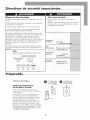
Exigences impo|'tantes
su_ ia raise & ia re|we
Votre nouvel appareil fonctionnera sur
n'importe quel circuit 115 volts, 60 Hz mis
la terre (prise
trois trous). Un circuit ind_pendant n'est
pas n_cessaire, mais il est quand m_me
recommand_ de ne pas surcharger le circuit
avec des appareils 5 haut rendement, p. ex.
des machines 5 laver, etc. Pour plus de
s_curit_, cet appareil est pourvu d'une fiche
branche de malt etdoit @re branch_ 5 une
prise mise/_ la terre (Fig. 1 et 2). Si votre prise
d'alimentation n'est pas approprKe. IL VOUS
INCOMBE DE BRANCHE DE MALT. NE PAS
UTILISER D'ADAPTATEUR.
Prise d'allmentafion D Prise d'ailmentafionmura[e _ deux mura[e/_ une entr6e
entr6es avec mlse & avec mlse _ la terre
la terre
Fiche m_ile a trois
branches
17

Pr6paratifs o0 ooooooo 0 o0 oooo o o0 ooooooo 0 o0 oooo
* Lire le manuel d'instructions avant de faire
fonctionner l'appareil pour la premiere fois.
Le manuel contient des renseignements sur l'utilisation et l'entretien de l'appareil, la garantie ainsi que des consignes
de s_curit_.
* Conserver ce document pour r_f_rence ult_rieure.
* l_viter de mettre l'appareil en marche s'il est endommag_.
* L'assemblage et le branchement de cet appareil doivent _tre effectu_s confonr_@_ent aux instructions de la garantie.
Renseignernents importants
1. Le cordon d'alimentation est situ_ a l'arri_re de l'appareil.
2. l_viter le contact de l'appareil avec l'eau.
3. Ne pas couvrir l'entr_e ni la sortie d'air de l'appareil.
4. L'appareil dolt _tre ad_quatement ventil_ vers l'ext_rieur en permanence.
AprOs avoir arrOt_ le systOme, attendre au moins 3 minutes avant de le remettre en mar&e.
t*appareil est pourvu de roulettes destin&s a faciliter son transport. S*ilest n&essaire d'incliner Yappardl, le r_servoir de celui-ci doit
d*abord Otre vid_ (utiliser le robinet de vidange situ_ au bas de I*appardl).
Rdfdrez-vous,_la section Avantde transporterI'appareil ou De le rangerpour la saison.
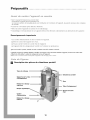
Description des pi&ces du climatiseur portatif
Rebinet de vidange
sup6rJeur
C|irnatiseur pertat||
_use
Tube d'6chapperuent
Beuche d'entr6e
d'aJr
18

Pr paratifs o0 ooooooo 0 o0 oooo o o0 ooooooo 0 o0 oooo
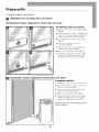
|nstallatio. darts .r=e fen_tre
1, Placer la buse dans le tube d'_chappement
(Fig.4a).
2, Ouvrir la fen_tre et y placer l'adapteur pour
fen_tre, l_tirer l'adaptateur sur la largeur de
la fen_tre puis fermer celle-ci (Fig.4b).
3. Fixer l'adaptateur _ l'appui de la fen_tre.
(Fig,.4c)
4. InsUrer la buse dans la rainure de
l'adaptateur (Fig.4d).
5. S_lectionner un niveau de climatisation:
normal ou _lev_ (High) (Fig. 6).
6, R_gler _ la temperature d_sir_e (Fig.6).
7. L'orientation du jet d'air peut _tre r_gl_e
l'aide de la poign_e situ_e sur la pattie
sup_rieure du panneau de commande.
Ciimatisatio. iorsque i'appareii est _ont_ darts une porte
|nstallation Mobile
1=Placer la buse dans un tube d'_chappement.
2, Entrebfiiller la porte et placer la buse entre
celle-ci et le montant (Fig.5).
3. S¢lectionner un niveau de climatisation:
normal ou ¢lCve (High) (Fig,.6).
4. R_gler _ la temperature dCsirCe (Fig,.6).
5. L'orientation du jet d'air peut _tre rCglCe
l'aide de la poignCe situCe sur la pattie
supCrieure du panneau de commande.
/ /
Important:Eviterd _tirer le tube d &happement ou de
le tordre inutilement.
19
La page est en cours de chargement...
La page est en cours de chargement...
La page est en cours de chargement...
La page est en cours de chargement...
La page est en cours de chargement...
La page est en cours de chargement...
-
 1
1
-
 2
2
-
 3
3
-
 4
4
-
 5
5
-
 6
6
-
 7
7
-
 8
8
-
 9
9
-
 10
10
-
 11
11
-
 12
12
-
 13
13
-
 14
14
-
 15
15
-
 16
16
-
 17
17
-
 18
18
-
 19
19
-
 20
20
-
 21
21
-
 22
22
-
 23
23
-
 24
24
-
 25
25
-
 26
26


Maytag 23-11-2222N-001 Manuel utilisateur
- Catégorie
- Climatiseurs split-system
- Taper
- Manuel utilisateur
dans d''autres langues
- English: Maytag 23-11-2222N-001 User manual
- español: Maytag 23-11-2222N-001 Manual de usuario
Documents connexes
Autres documents
-
Laser SPK-Q14PBD Manuel utilisateur
-
 Hampton Bay HBP070 Le manuel du propriétaire
-
 Hampton Bay PORTABLE AIR CONDITIONER Installation & Operation Manual
-
Fedders 23-23-0338N-002 s Installation & Operation Manual
-
-
-
-
-
-

