DCS BE148RCL Le manuel du propriétaire
- Catégorie
- Barbecues
- Taper
- Le manuel du propriétaire

OUTDOOR GRILL
36 & 48" BE models
GRIL EXTÉRIEUR
Modèles 36 et 48" BE
INSTALLATION GUIDE/USER GUIDE
GUIDE D’INSTALLATION/GUIDE D’UTILISATION
US CA


1
CONTENTS
IMPORTANT!
SAVE THESE INSTRUCTIONS
The models shown in this user guide may not be available in all markets and are subject to change at any time. For current details about
model and specification availability in your country, visit our website listed on the back cover or contact your DCS by Fisher & Paykel dealer.
Safety and warnings 3
Grill models 6
Product dimensions 7
Installation
Locating grill / built-in clearances 8
Built-in construction details 13
Gas hook-up 15
Leak testing 18
Electrical connection 19
Burner adjustment 20
Radiant assembly 21
Installer checklist 22
Using the grill
Lighting instructions 24
Grilling 25
Using the grates 32
Using the charcoal insert 33
Using the rotisserie 34
Accessories 39
Care & maintenance 40
Troubleshooting 44
Warranty and Service 45
EN

2
A MESSAGE TO OUR CUSTOMERS
Thank you for selecting this DCS Evolution Series Grill. This installation and user guide contains
valuable information on how to properly install, operate and maintain your new appliance for
years of safe and enjoyable cooking.
Please fill out and submit your Product Registration by visiting our website at www.
dcsappliances.com and selecting “Support” on the home page and then selecting “Product
Registration”. In addition, keep this guide handy, as it will help answer questions that may arise as
you use your new appliance.
For your convenience, product questions can be answered by a DCS Customer Care
Representative at www.dcsappliances.com, or email: customer.care@fisherpaykel.com.
Please write the model, code, and serial numbers on this page for reference (this can be found on
the inside, right side panel behind the drip pan handle. See page 22.)
MODEL NUMBER CODE SERIAL NUMBER
IMPORTANT!
DO NOT discard any packing material (box, pallet, straps) until the unit has been inspected.
Inspect the product to verify that there is no shipping damage. If any damage is detected, call
the shipper and initiate a damage claim. DCS by Fisher & Paykel is not responsible for shipping
damage.

3
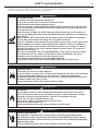
SAFETY AND WARNINGS
WARNING!
Fire Hazard
Do not operate the grill under un protected combustible construction. Use only in
well ventilated areas. Do not use in buildings, garages, sheds, breezeways, covered
structures or other such enclosed areas. This unit is for outdoor use only.
Never leave the grill unattended when in use.
Never store a spare LP cylinder under or near this unit.
Never fill the tank beyond
¾
full.
Failure to follow this advice may result in death or serious injury.
WARNING!
Hot Surface Hazard
Accessible parts may become hot during use.
Do not touch surface units or areas near units of the grill.
Hood must be opened before lighting the grill.
Never let clothing or other flammable materials come in contact with or get too close
to any grate, burner or hot surface until it has cooled. Fabric may ignite and result in
fire or personal injury.
Never lean over an open grill. When lighting a burner, always pay close attention to
what you are doing. Be certain you are pushing the burner knob when you attempt to
light the grill.
When using the grill, do not touch the grill burner, grate, or immediate surrounding
area as these areas become extremely hot and could cause burns.
Grease is flammable. Never operate the grill without a grease tray. Let hot grease cool
before attempting to handle it. Avoid letting grease deposits collect in the drip pan.
Clean the grill with caution. Avoid steam burns; do not use a wet sponge or cloth to
clean the grill while it is hot. Some cleaners produce noxious fumes or can ignite if
applied to a hot surface.
Use only dry potholders; moist or damp potholders on hot surfaces may cause burns
from steam. Do not use a towel or bulky cloth in place of potholders. Do not let
potholders touch hot portions of the grill or burner grate.
To avoid burns when cooking, use long handled BBQ tools.
Failure to follow this advice may result in burns and scalds or serious injury.
!
WARNING!
Explosion Hazard
If you smell gas, do not use the appliance.
Do not use water on grease fires, a violent steam explosion may result. Turn all burners
off, then smother fire or flame or use dry chemical or foam-type extinguisher.
Do not heat unopened food containers such as cans – Build up of pressure may cause
container to burst and result in injury.
Failure to follow this advice may result in injury or death.
!
!
To reduce the risk of fire, electrical shock, injury to persons, or damage when using the appliance,
follow the important safety instructions listed below:
WARNING!
Electrical Shock Hazard
This appliance is equipped with a three-prong or four-prong grounding plug for
your protection against shock hazard and should be plugged directly into a properly
grounded power outlet. Do not under any circumstances cut or remove the grounding
prong from this plug.
Failure to follow this advice may result in death or electrical shock.
!
EN

4
SAFETY AND WARNINGS
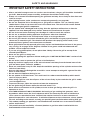
IMPORTANT SAFETY INSTRUCTIONS!
y After a period of storage or non-use (such as over the winter), the gas grill should be checked for
gas leaks, deterioration, proper assembly, and burner obstructions before using.
y Always use a covered hand when opening the grill hood and only do so slowly to allow heat and
steam to escape.
y After lighting burners, make sure burners are operating normally (see page 20).
y Do not use aluminium foil to line drip pans or grill grates or radiants. This can severely upset
combustion air flow or trap excessive heat in the control area. The result of this can be melted
knobs or damaged ignition components.
y Do not operate with a damaged cord or plug, after the appliance malfunctions or after the
appliance has been damaged in any manner. Contact the manufacturer for repair.
y Do not let the rotisserie cord hang over the edge of a table or touch hot surfaces.
y Do not use an outdoor cooking appliance for purposes other than intended.
y Do not use lighter fluid in the charcoal burner insert or on the gas burners.
y Be sure all grill controls are turned off and the grill is cool before using any type of aerosol
cleaner on or around the grill. The chemical that produces the spraying action could, in the
presence of heat, ignite or cause metal parts to corrode.
y Never grill without the drip pan and grease tray in place and hooked into the front of the grease
tray (see Fig. 34 on page 40 for diagram). Without it hot grease could leak downward and
produce a fire or explosion hazard.
y If you are using griddle plates, do not place them side by side on the grill or on top of the
Infrared Hybrid Burner.
y Never use the grill in a windy area.
y Do not try lighting this appliance without reading the “LIGHTING INSTRUCTIONS” section of this
manual.
y Do not locate, store or operate the grill on an inclined plane.
y Keep any electrical supply cord, or the rotisserie motor cord away from the heated areas of the
grill and water (pools, fountains, puddles).
y Never use a dented or rusty LP tank. Keep the ventilation openings of the cylinder enclosure free
and clear from debris.
y Have an ABC rated Fire Extinguisher accessible – never attempt to extinguish a grease fire with
water or other liquids.
y Do not move the appliance during its use.
y Do not operate in enclosed areas. This could result in carbon monoxide build-up which would
result in injury or death.
y When using a grill, be sure that all parts of the unit are firmly in place and that the grill is stable
(can’t be tipped over).
y To put out flare-ups, adjust the controls to lower the temperature
y Do not ignite the grill burners while the rotisserie burner is lit.
y Never attach or disconnect an LP cylinder, or move or alter gas fittings when the grill is in
operation or is hot.
y CALIFORNIA PROPOSITION 65-WARNING: the burning of gas cooking fuel generates some
by-products which are on the list of substances which are known by the State of California to
cause cancer or reproductive harm. California law requires businesses to warn customers of
potential exposure to such substances. To minimize exposure to these substances, always operate
this unit according to the manual, ensuring you provide good ventilation when cooking with gas.
y This outdoor cooking gas appliance is not intended to be installed in or on recreational vehicles,
trailers and/or boats.
y This product must be installed by a licensed plumber or gas fitter when installed within the
Commonwealth of Massachusetts.

5
SAFETY AND WARNINGS
IMPORTANT SAFETY INSTRUCTIONS!
y Certain Liquid Propane dealers may fill liquid propane cylinders for use in the grill beyond
cylinder filling capacity. This “overfilling” may create a dangerous condition. “Overfilled” tanks
can build up excess pressure. As a safety device, the tank pressure relief valve will vent propane
gas vapor to relieve this excess pressure. This vapor is combustible and therefore can be ignited.
To reduce this danger, you should take the following safety precautions:
y When you have your tank filled, be sure you tell the supplier to fill it to no more than
¾
(75%)
of its total capacity.
y If you own or use a spare tank, or have a disconnected tank, you should NEVER store it near
or under the grill unit or heat box, or near any other ignition or heat source. A metallic sticker
with this warning is provided with the grill. Install this sticker close to your barbeque grill.
y Do not store a full tank in direct sunlight.
y Push in and turn the selected control knob to HI/SEAR position. Release the knob when the
burner lights. If burner does not light in four to five seconds, turn knob “OFF” and wait five
minutes before trying again so any accumulated gas may dissipate.
y Before each use, inspect the gas supply piping or hose prior to turning the gas “ON”. If there is
evidence of cuts, wear, or abrasion, it must be replaced prior to use.
y Follow the installation instructions within this manual. Have your grill installed by a qualified
installer. Have the installer show you where the gas supply shut-off valve is located so that you
know where and how to shut off the gas to the grill. If the connections are not perfectly sealed,
you can have a small leak and therefore a faint gas smell. Some leaks can only be found with the
burner control in the “ON” position - this must be done by a qualified technician.
y Children should not be left alone or unattended in an area where the grill is being used. Never
allow them to sit, stand or play on or around the grill at any time. When in use, portions of the
grill get hot enough to cause severe burns.
y Do not store items of interest to children around or below the grill.
y Clean and perform general maintenance on the grill twice a year. Watch for corrosion, cracks,
or insect activity. Check the regulator, hoses, burner ports, air shutter, and venturi/valve section
carefully. Always turn off gas at the source (tank or supply line) prior to inspecting parts.
y Never use the grill burners while the rotisserie burner is lit.
EN

6
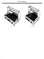
BE1-36RBE1-48R
GRILL MODELS

7
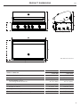
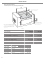
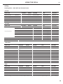
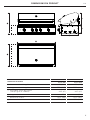
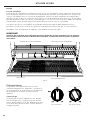
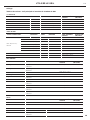
PRODUCT DIMENSIONS
PRODUCT DIMENSIONS
BE1-48R BE1-36R
Inches (mm) Inches (mm)
A
Overall height of grill
27 1/4" (692) 27 1/4" (692)
B
Overall width of grill
47 15/16" (1217) 35 15/16" (912)
C
Overall depth of grill
(excluding handle and dials)
26 7/8" (682) 26 7/8" (682)
D
Depth of chassis
22" (559) 22" (559)
E
Height of chassis
9 15/16" (252) 9 15/16" (252)
f
Height of hood
17 7/16" (443) 17 7/16" (443)
G
Overall width of grill with storage unit attached
53 15/16" (1369) 23 7/16" (1065)
A
e
f
c
B
G
d
BE1-48R Model Illustrated
EN

8
INSTALLATION
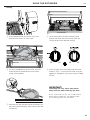
Locating Grill/Built-in Clearances
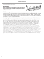
IMPORTANT!
Before installation, remove shipping brackets from the grill.
Loosen the four screws. Slide the shipping bracket off and
re-tighten the screws.
Location
When determining a suitable location, take into account concerns such as exposure to wind,
proximity to traffic paths and keeping any gas or electrical supply lines as short as possible and away
from heat sources. Locate the grill only in a well ventilated area. Do not build the grill under overhead
unprotected combustible construction. Never locate the grill in a building, garage, breezeway, shed
or other such enclosed areas. During heavy use, the grill will produce a lot of heat and smoke. Ensure
that the grill is used in a well ventilated area.
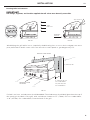
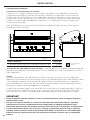
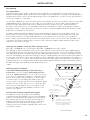
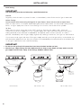
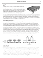
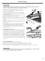
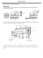
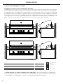
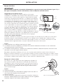
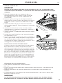
If locating the grill in a windy area, try to locate the grill so the prevailing wind will blow air at the
front of the grill as shown in Fig. 01b. This will assist the grill in venting hot air through the back of
the grill. In addition, this will help keep any smoke from blowing at someone who is cooking on the
grill. If you have to locate the grill in a windy area where the prevailing wind is at the rear of the
grill (Fig. 01a), a windscreen must be installed. The windscreen should be set-up so that it blocks
wind from entering the exhaust vent in the rear of the unit as shown in Fig. 01c. Location of the
windscreen relative to rear of the grill must adhere to the clearances specified for combustible or
non-combustible construction as defined in these instructions. Refer to following pages.
As a high-performance gas appliance, your grill requires significant amounts of air to support the
combustion process. Your grill is designed to take air in through the valve panel area, and send the
exhaust products out through the exhaust gap at the rear of the hood. Using your grill in windy
conditions can disrupt the proper flow of air though your grill, leading to reduced performance, or in
certain severe cases, causing heat buildup in the valve panel area. This can lead to problems such as
having the knobs melt, or burn hazards when the valve panel surfaces become too hot to touch.
Please note that damage to your grill resulting from use in windy conditions, such as melted knobs or
igniter wires, or valve panel discoloration from heat build-up, are excluded from warranty coverage.

9
INSTALLATION
Locating Built-in Clearances
IMPORTANT!
Gas fittings, regulator, and installer supplied shut-off valves must be easily accessible.
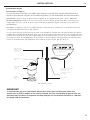
Wind hitting the grill while in use, (especially wind blowing into or across the hood gap) can cause
poor performance and in some cases can cause the control panel to get dangerously hot.
If wind is an issue, a windscreen should be added. The windscreen should be higher than the top of
the opening in the back of the grill, with a minimum clearance of 3” (76mm) for non-combustibles,
or 18” (457mm) for combustibles, from the back of the grill
PRIMARY INTAKE
AIR FLOW
EXHAUST VENT FLOW
WIND
WIND
WIND
15” (381 mm) min.
3” (76 mm) min. for
non-combustibles
18” (457 mm) min.
for combustibles
FIG. 01c
FIG. 01a FIG. 01b
PREFERRED
AIR FLOW
WIND
DIRECTION
GRILL EXHAUST
EXHAUST
FLAME LIFT
EXHAUST
PREFERRED
AIR FLOW
WIND
DIRECTION
GRILL EXHAUST
EXHAUST
FLAME LIFT
EXHAUST
EN

10
INSTALLATION
General
The grill is designed for easy placement into built-in masonry enclosures. For non-combustible
applications the grill drops into the opening shown in Fig. 05 and hangs from its side flanges. Adeck
is not required to support it from the bottom. When using the insulated jacket in a combustible
enclosure application, see the Fig. 06. The insulation jacket assembly must be supported from the
bottom by a ledge on each side and back or a solid deck.
A spirit level should be used to ensure that the unit is level both front-to-back and side-to-side. Ifit
is not level, burner combustion may be erratic or the unit may not function efficiently for grease
flow. If the floor is uneven, re-leveling may be required whenever a freestanding unit is moved.
AAA
A A
A
AAA
A A
A
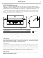
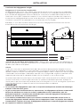
Clearances to non-combustible construction*
A minimum of 3” (76mm) clearance from the back of the grill to non-combustible construction
is required for the purpose of allowing the hood to open fully. It is desirable to allow at least 6”
(153mm) rear and side clearance to non-combustible construction above the cooking surface for
counter space. If you’ll be using the rotisserie option, the space is essential for motor and skewer
clearance. The grill can be placed directly adjacent to non-combustible construction below the
cooking surface (Fig. 02).
Note: if intending to use the rotisserie, the minimum clearance will be from the rotisserie motor
instead of the side of the grill.
*DEFINITION OF NON-COMBUSTIBLE MATERIAL - Material which is not capable of being ignited and
burned, such as materials consisting entirely of, or a combination of, steel, iron, brick tile, concrete,
slate, and plaster.
Locating Built-in Clearances
IMPORTANT!
y Failure to maintain required clearances creates a fire hazard that may result in property damage or
serious personal injury.
y The grill is designed to function in an open area. Recommended minimum clearances should be
maintained to all surfaces (combustible and non-combustible) for optimum performance. Non-
combustible material within the minimum clearance area could result in discoloration or deterioration.
y If a non-combustible material such as stucco is covering a combustible material such as wood, the
minimum clearance distance needs to be considered for wood. The presence of a non-combustible
material inside the clearance zone does not eliminate the minimum clearance zone to combustible
material.
FIG. 02
PRODUCT DIMENSIONS INCHES (MM)
A
Minimum distance from non-combustible surface to grill
3" (76)
NON-COMBUSTIBLE
SURFACE
=

11
INSTALLATION
Locating Built-in Clearances
Insulated jacket
If the grill is to be placed into a combustible enclosure, an approved insulated jacket is necessary.
Insulated jackets are available from your dealer. Use only the DCS insulated jacket which has
specifically been designed and tested for this purpose. Review the detail drawing shown (Fig. 06)
and take into account the provisions shown for gas line hook-up clearance in the right rear corner.
It is required that ventilation holes are provided in the enclosure to eliminate the potential build-up
of gas in the event of a gas leak. The supporting ledges or deck must be level and flat and strong
enough to support the grill and insulated jacket. The counter should also be level.
IMPORTANT!
Installing this product into a combustible enclosure without an insulated jacket could result in fire,
property damage and personal injury.
A
AA
A A A
A
AA
A A A
FIG. 03
**DEFINITION OF COMBUSTIBLE MATERIAL - Any materials of a building structure or decorative
structure made of wood, compressed paper, plant fibers, vinyl/plastic or other materials that
are capable of transferring heat or being ignited and burned. Such material shall be considered
combustible even though flame-proofed, fire-retardant treated or surface-painted, or plastered.
IMPORTANT!
It is recommended that a minimum of two 12 1/4x12 1/4" (311 x 311mm) vents be provided in order to
safely dissipate unburned gas vapors in the event of a gas supply leak. These are to be located on
each side of the enclosure and within 5" (127mm) of the top.
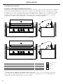
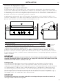
Clearances to combustible construction**
Minimum of 18” (457mm) from the sides and rear of grill must be maintained to adjacent vertical
combustible construction, above the counter top level. Intense heat, and large volumes of smoke will
exhaust from the rear of the grill (Fig. 01b). This may discolor or damage unprotected areas. Do not
install under unprotected combustible construction without using a fire safe ventilation system.
A 18” (457mm) minimum clearance must be maintained under the counter top to combustible con-
struction. The clearance can be modified by a use of an insulated jacket. Insulated jackets can be
purchased from our website, www.dcsappliances.com.
PRODUCT DIMENSIONS INCHES (MM)
A
Minimum distance from combustible surface to grill
18" (457)
COMBUSTIBLE
SURFACE
=
EN

12
INSTALLATION
A
A AA
B B B
A
B
B
B
A
A
A
A
A
B B
B
A
B BB
A
A
A AA
B B B
A
B
B
B
A
A
A
A
A
B B
B
A
B BB
A
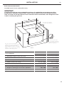
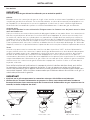
Clearances to protected combustible construction***
A minimum of 12" (305mm) clearance from the sides and rear of grill must be maintained to adjacent
vertical protected combustible construction. Intense heat, and large volumes of smoke will exhaust
from the rear of the grill. This may discolor or damage unprotected areas. The 12" (305mm) includes
4" (102mm) min. non-combustible material plus an additional 8" (203mm) min. clearance between
the grill and the protected combustible construction. This can be achieved by brick or concrete
(Fig.04a) or a metal stud finished with non-combustible substrate (Fig. 04b).
***DEFINITION OF PROTECTED COMBUSTIBLE SURFACE - A wall of non-combustible material in
front a wall of combustible material, to act as a barrier. For definitions of non-combustible and
combustible material, please refer to previous pages.
Locating Built-in Clearances
FIG. 04b
FIG. 04a
PRODUCT DIMENSIONS INCHES (MM)
A
Minimum non-combustible surface width
4" (102)
B
Minimum distance from combustible surface to grill
12" (305)
NON-COMBUSTIBLE
SURFACE
COMBUSTIBLE
SURFACE
METAL STUD
=
=
=

13
INSTALLATION
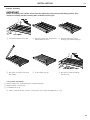
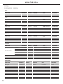
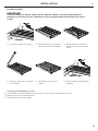
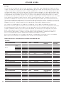
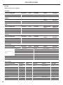
CAVITY DIMENSIONS
BE1-48R BE1-36R
Inches (mm) Inches (mm)
A
Maximum height of enclosure shell
35 1/2" (902) 35 1/2" (902)
B
Depth of enclosure shell
22 3/4" (578) 22 3/4" (578)
C
Minimum depth for hood swing
3 3/4" (95) 3 3/4" (95)
D
Width of enclosure cavity
45 3/4" (1162) 34 1/2" (876)
E
Height of enclosure cavity
10 1/8" (257) 10 1/8" (257)
f
Depth to gas supply opening
18 1/2" (470) 18 1/2" (470)
G
Height of opening for access doors/drawers
20" (508) 20" (508)
H
Width of opening for access doors/drawers
46" (1168) 34" (864)
Standard layout for non-combustible enclosure:
NOTE: If using a backguard
apron or rear wall, locate
electrical service on the
right hand side for rotisserie
motor connection
48" Models = 116,2 cm/45 3/4 "
36" Models = 87,6 cm/34 1/2"
9,5cm / 3 3/4" Min. for Lid
10,16 x 10,16cm
(4 x 4 ") opening
for gas supply
line
57,79 cm/22 3/4 "
46.36 cm/
18 1/2 "
25,72 cm/
10 1/8 "
64,5 cm
2
/10
"2
min
ventilation
left
64,5 cm
2
/10
"2
Min. ventilation
on the back side
2,54 cm/1 " min.
WARNING!
If installing the grill into
a non-combustible
enclosure, all
combustible
construction must still
be outside the 18 inch
clearance zone. If your
island is made of stucco
over the top of wooden
studs, the wood can not
be inside the 18 inch
clearance zone to
combustible, even
though the stucco is
what is touching the
grill area.
D
E
G
H
F
A
B
C
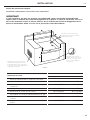
Built-in Construction Details
Standard layout for non-combustible cavity
IMPORTANT!
If installing the grill into a non-combustible enclosure, all combustible construction must still be
outside the 18" (457mm) clearance zone. If your island is made of stucco over the top of wooden
studs, the wood can not be inside the 18 inch clearance zone to combustible, even though the stucco
is what is touching the grill area.
Note: the enclosure should have
ventilation holes to prevent gas build-up
in the event of a leak. Refer to ANSI
Z21.58 Standard for Outdoor Cooking Gas
Appliances, Section 1.7 Enclosures For Self
Contained LP-Gas Supply Systems.
Note: 4x4” (102 x 102mm)
opening for gas supply line
FIG. 05
Note: the cut-out of each
corner should be a 90°angle
in order for the access doors/
drawers to fit properly.
EN

14
INSTALLATION
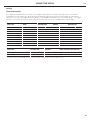
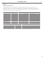
CAVITY DIMENSIONS
BE1-48R BE1-36R
Inches (mm) Inches (mm)
A
Maximum height of enclosure shell
35 1/2" (902) 35 1/2" (902)
B
Depth of enclosure shell
22 3/4" (578) 22 3/4" (578)
C
Minimum depth for hood swing
3 3/4" (95) 3 3/4" (95)
D
Width of enclosure cavity
51 5/8" (1318) 40 1/2" (1029)
E
Height of enclosure cavity
11 1/8"(283) 11 1/8"(283)
f
Depth to gas supply opening
18 1/2"(470) 18 1/2"(470)
G
Height of opening for access doors/drawers
20" (508) 20" (508)
H
Width of opening for access doors/drawers
46" (1168) 34" (864)
ACCESS DOORS
MODEL NUMBER
ACCESS DRAWERS
MODEL NUMBER
CAVITY WIDTH CAVITY HEIGHT
Inches (mm) Inches (mm)
ADN1-20x48 ADR2-48 46" (1168) 20" (508)
ADN1-20x36 ADR2-36 34" (864) 20" (508)
ADN1-20x30 ADR2-30 28" (711) 20" (508)
ADN1-20x24 ADR2-24 22" (559) 20" (508)
D
E
G
H
F
A
B
C
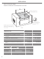
Built-in Construction Details
Standard layout for cavity including insulated jacket
Note: the enclosure should have ventilation
holes to prevent gas build-up in the event
of a leak. Refer to ANSI Z21.58 Standard for
Outdoor Cooking Gas Appliances, Section
1.7 Enclosures For Self Contained LP-Gas
Supply Systems.
Note: the cut-out of each
corner should be a 90°angle
in order for the access doors/
drawers to fit properly.
Note: 4x4” (102mm x 102mm)
opening for gas supply line
FIG. 06
To order access drawers or doors, please visit www.dcsappliances.com for further details.

15
INSTALLATION
Gas Hook-up
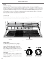
Gas requirements
Verify the type of gas supply to be used, either natural or LP, and make sure the marking on the
appliance rating plate agrees with that of the supply. The rating plate is located on the underside of
the drip tray. Never connect an unregulated gas line to the appliance. You must use a gas regulator
even if the supply is controlled.
An installer-supplied gas shut-off valve must be installed in an easily accessible location. All installer
supplied parts must conform to local codes, or in the absence of local codes, with the National
Electrical Code, ANSI/NFPA 70 or the Canadian Electrical Code, CSA C22.1, and the National
Fuel Gas Code, ANSI Z223.1 or CSA-B149.1 Natural Gas Installation Code or CSA-B149.2 Propane
Installation Code. In Massachusetts such shut-off valves should be approved by the Board of State
Examiners or Plumbers & Gas Fitters.
All pipe sealants must be an ap proved type and resistant to the actions of LP gases. Never use
pipe sealant on flare fittings. All gas connections should be made by a qualified technician and
in accordance with local codes and ordinances. In the absence of local codes, the installation
must comply with the National Fuel Gas Code ANSI Z223.1. Gas conversion kits are available from
Customer care. When ordering gas conversion kits, have the model number, and the type of gas
(natural or LP) from your grill.
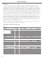
Total gas consumption of the grill with all burners on HI
BE1-48R - 118,000 Btu/hr or 124.5 Mj/hr BE1-36R - 89,000 Btu/hr or 93.3 Mj/hr
The appliance and its individual shut-off valve must be disconnected from the gas supply piping
system during any pressure testing of that system at test pressures in excess of 1/2 PSIG (3.5 kPa).
The appliance must be isolated from the gas supply piping system by closing its individual manual
shut-off valve during any pressure testing of the gas supply piping system at test pressures equal to
or less than 1/2 PSIG (3.5 kPa). The installation of this appliance must conform with local codes or,
in the absence of local codes, with the National Fuel Gas Code, ANSI Z223.1/NFPA 54. Installation in
Can ada must be in accordance with Natural Gas and Propane Installation Code, CSA B149.1, and/or
Propane Storage and Handling Code, B149.2 and local
codes.
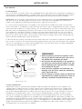
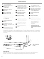
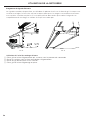
Natural gas built-in hook-up
(This should be performed by a technician only.)
Connection: 1/2” NPT female. Operating pressure:
4.0” W.C. Supply pressure: 5” to 14” WC. If in excess
of 14” W.C. a step down regulator is required. Check
with your local gas utility company or local codes
for instructions on installing gas supply lines. Be
sure to check on type and size of run, and how deep
to bury the line. If the gas line is too small, the grill
will not function properly. Any joint sealant used
must be an approved type and be resistive to the
actions of LP gases.
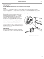
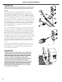
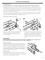
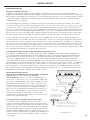
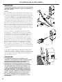
To hook-up the fittings supplied with the grill
Assemble as shown (Fig. 07). Use threading
compound on male threads only. Use a second pipe
wrench to hold the grill inlet pipe to avoid shifting
any internal gas lines of the grill. Ensure that the
regulator arrow points in the direction of gas flow
towards the unit, away from the supply. Do not
forget to place the installer-supplied gas valve in an
accessible location.
*Installation must conform
with local codes or with the
National Fuel Gas Code ANSI
Z223.1 or the CSA-B149.2
Propane Installation Code
Coupling
1/2” NPT
x 2.0”
NIpple
Regulator
4.0" W.C.
Bottom of unit
Threading compounds
(Must be resistant to
LP gas)
1/2” NPT x
5.0" Nipple
Installer supplied
shut-off valve must be
easily accessible*
FIG. 07 Natural Gas
EN

16
INSTALLATION
Gas Hook-up
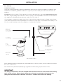
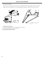
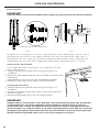
LP cart hook-up
Grills orificed for use with LP gas come equipped with a high capacity hose/regulator assem bly for
connection to a standard 20 lb. LP cylinder (Type 1). The LP tank is not included.
The grill system is
leak tested, do not remove the Regulator/Hose assembly from the grill during cart installation.
Connection: LP Hose with a Type 1 quick disconnect and regulator is included. Operating pressure:
11.0”W.C. Note: all gas piping and connectors must conform to the Standard for Connectors for
Outdoor Gas Appliances and Manufactured Homes, ANSI Z21.75/CSA 6.27.
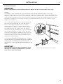
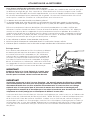
To connect the LP regulator/hose assembly to the tank/valve assembly, first make sure the main
valve on the tank is completely closed. Although the flow of gas is stopped when the Type 1 system
is disconnected as part of its safety feature, you should always turn off the LP tank main valve (Fig.
08) after each use and during transport of the tank or unit. Insert the regulator inlet into the tank
valve and turn to the black coupler clockwise until the coupler tightens up. Do not over tighten
the coupler. Turn the main tank valve on and turn the burner control valves on the unit to the “HI”
position for about 20 seconds to allow the air in the system to purge. Turn valves off and wait five
minutes before attempting to ignite the burners.
To disconnect the coupler, first make sure the main tank valve is turned off. Grasp the coupler and
turn counter clockwise. The inlet will then disengage. Remove the inlet from the tank valve opening
if it has not already done so when it disengaged. Your local LP filling station should be equipped
with the proper equipment to fill your tank.
LP tank requirements:
A dented or rusty LP tank may be hazardous and should be checked by your LP supplier. The
cylinder that is used must have a collar to protect the cylinder valve. Never use a cylinder with
a damaged valve. Always check for leaks after every LP tank change. The LP gas cylinder must
be constructed and marked in accordance with the specifications for LP gas cylinders of the U.S.
Department of Transportation
(DOT or CAN/CSA-B339)
and designed for use with a Type 1 system
only. Do not change the regulator/hose assembly from that supplied with the unit or attempt to
use a Type 1 equipped regulator/hose assembly with a standard 510 POL tank/valve assembly. The
cylinder must be provided with a shut-off valve terminating in an LP gas supply cylinder valve outlet
specified, as applicable, for connection Type 1. If the appliance is stored indoors, the cylinder must
be disconnected and removed from the appliance. Cylinders must be stored outdoors in a well-
ventilated area out of the reach of children.
IMPORTANT!
y Before connecting LP tank to regulator, check
that all grill burners and rotisserie valves are in
the OFF position and open grill hood.
y Do not place the Grill directly on the ground or
any other flat surface without support. This will
prevent damaging the regulator/hose assembly
by the weight of the grill.
y Check the hose, regulator and connectors for
damage. Look for cracks, abrasions, brittleness,
holes, dents and nicks.
y Do not attempt to remove, repair, or replace the
regulator/hose assembly by yourself. It must be
done by a qualified licensed technician only.
Bottom of unit
Elbow 45°
1/2” female
NPT x 3/8” male flare
(installed on the unit)
LP Regulator hose
assembly 11" W.C.
Type 1 Regulator
Main Tank Valve
20 lb.
LP Tank
*Installation must conform
with local codes or with the
National Fuel Gas Code ANSI
Z223.1 or the CSA-B149.2
Propane Installation Code
FIG. 08 LP Gas - Cart

17
INSTALLATION
Gas Hook-up
Connection: LP Hose with a Type 1 quick disconnect and regulator is included. Operating pressure:
11.0”W.C. All gas piping and connectors must conform to the Standard for Connectors for Outdoor
Gas Appliances and Manufactured Homes, ANSI Z21.75/CSA 6.27.
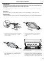
If you intend to operate your built-in grill on LP gas utilizing a 20v lb type 1 cylinder, then a built-
in LP tank restraint must be installed prior to initial use of the grill. The Installer must supply ½” ID
Flex hose and fixed pipe and a flare adaptor as indicated in Fig. 09.
Note:
when an LP unit is being directly connected to an LP house system, you must follow the natural
gas hook up guidelines.
The installer must provide the proper gas regulator to reduce the gas pressure to 11” W.C.
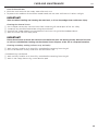
LP built-in hook-up
If the grill is to be installed in a built-in application, then the grill must be installed in accordance with
the built–in installation guidelines and
the LP regulator/hose assembly must be removed from the
product
.
IMPORTANT!
Gas piping and connectors must be clamped within the the enclosure to avoid contact with moving
parts and hot surfaces. Where the gas piping passes through an opening in the enclosure, the
piping must be protected for a distance of at least 2” (50mm) either side of the opening.
Bottom of unit
LP regulator/
hose assembly
Enclosure wall
1/2” ID flex hose with
1/2” NPT fittings
(not supplied)
1/2” NPT fixed pipe
(not supplied)
Adapter 3/8”
flare fitting
1/2” NPT female
(not supplied)
20 lb
LP Tank
(not supplied)
Tank retention
device (not
supplied)
FIG. 09 LP Gas - Built-in
EN

18
INSTALLATION
Leak Testing
IMPORTANT!
Gas leak testing must be carried out by a qualified technician.
General
Regularly check the whole system for leaks, or immediately check if the smell of gas is detected.
Before Testing
Do not smoke while leak testing. Extinguish all open flames. Never leak test with an open flame.
Make a soap solution of one part liquid detergent and one part water. You will need a spray bottle,
brush, or rag to apply the solution to the fittings. For LP units, check with a full cylinder.
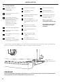
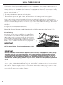
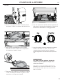
To Test
Make sure all control valves are in the “OFF” position. Turn the gas supply “ON”. Check all
connections from the supply line, or LP cylinder. Apply the soap solution around the connection,
tubing and end of the manifold. Soap bubbles will appear where a leak is present. If a leak is
present, immediately turn off gas supply, tighten any leaking connections, turn gas on, and recheck.
If you cannot stop a gas leak turn off the gas supply and call your local gas utility, or the dealer you
purchased the appliance from. Only those parts recommended by the manufacturer should be used
on the grill. Substitution can void the warranty.
IMPORTANT!
y Do not use the grill until all connections have been checked and do not leak.
y Check all gas supply fittings for leaks before each use. Keep a spray bottle of soapy water near the
gas supply shut-off valve. Spray all the fittings, bubbles indicate leaks
BOTTOM OF UNIT
LEAK TEST POINTS
CHECK HOSES
FOR SIGNS OF
CRACKS, LEAKS
OR ABRASIONS
BOTTOM OF UNIT
LEAK TEST POINTS
FIG. 11 LP Gas - cart FIG. 12 LP Gas - built-in
FIG. 10 Nat. Gas
BOTTOM OF UNIT
LEAK TEST POINTS
CHECK HOSES
FOR SIGNS OF
CRACKS, LEAKS
OR ABRASIONS
La page est en cours de chargement...
La page est en cours de chargement...
La page est en cours de chargement...
La page est en cours de chargement...
La page est en cours de chargement...
La page est en cours de chargement...
La page est en cours de chargement...
La page est en cours de chargement...
La page est en cours de chargement...
La page est en cours de chargement...
La page est en cours de chargement...
La page est en cours de chargement...
La page est en cours de chargement...
La page est en cours de chargement...
La page est en cours de chargement...
La page est en cours de chargement...
La page est en cours de chargement...
La page est en cours de chargement...
La page est en cours de chargement...
La page est en cours de chargement...
La page est en cours de chargement...
La page est en cours de chargement...
La page est en cours de chargement...
La page est en cours de chargement...
La page est en cours de chargement...
La page est en cours de chargement...
La page est en cours de chargement...
La page est en cours de chargement...
La page est en cours de chargement...
La page est en cours de chargement...
La page est en cours de chargement...
La page est en cours de chargement...
La page est en cours de chargement...
La page est en cours de chargement...
La page est en cours de chargement...
La page est en cours de chargement...
La page est en cours de chargement...
La page est en cours de chargement...
La page est en cours de chargement...
La page est en cours de chargement...
La page est en cours de chargement...
La page est en cours de chargement...
La page est en cours de chargement...
La page est en cours de chargement...
La page est en cours de chargement...
La page est en cours de chargement...
La page est en cours de chargement...
La page est en cours de chargement...
La page est en cours de chargement...
La page est en cours de chargement...
La page est en cours de chargement...
La page est en cours de chargement...
La page est en cours de chargement...
La page est en cours de chargement...
La page est en cours de chargement...
La page est en cours de chargement...
La page est en cours de chargement...
La page est en cours de chargement...
La page est en cours de chargement...
La page est en cours de chargement...
La page est en cours de chargement...
La page est en cours de chargement...
La page est en cours de chargement...
La page est en cours de chargement...
La page est en cours de chargement...
La page est en cours de chargement...
La page est en cours de chargement...
La page est en cours de chargement...
La page est en cours de chargement...
La page est en cours de chargement...
La page est en cours de chargement...
La page est en cours de chargement...
La page est en cours de chargement...
La page est en cours de chargement...
La page est en cours de chargement...
La page est en cours de chargement...
-
 1
1
-
 2
2
-
 3
3
-
 4
4
-
 5
5
-
 6
6
-
 7
7
-
 8
8
-
 9
9
-
 10
10
-
 11
11
-
 12
12
-
 13
13
-
 14
14
-
 15
15
-
 16
16
-
 17
17
-
 18
18
-
 19
19
-
 20
20
-
 21
21
-
 22
22
-
 23
23
-
 24
24
-
 25
25
-
 26
26
-
 27
27
-
 28
28
-
 29
29
-
 30
30
-
 31
31
-
 32
32
-
 33
33
-
 34
34
-
 35
35
-
 36
36
-
 37
37
-
 38
38
-
 39
39
-
 40
40
-
 41
41
-
 42
42
-
 43
43
-
 44
44
-
 45
45
-
 46
46
-
 47
47
-
 48
48
-
 49
49
-
 50
50
-
 51
51
-
 52
52
-
 53
53
-
 54
54
-
 55
55
-
 56
56
-
 57
57
-
 58
58
-
 59
59
-
 60
60
-
 61
61
-
 62
62
-
 63
63
-
 64
64
-
 65
65
-
 66
66
-
 67
67
-
 68
68
-
 69
69
-
 70
70
-
 71
71
-
 72
72
-
 73
73
-
 74
74
-
 75
75
-
 76
76
-
 77
77
-
 78
78
-
 79
79
-
 80
80
-
 81
81
-
 82
82
-
 83
83
-
 84
84
-
 85
85
-
 86
86
-
 87
87
-
 88
88
-
 89
89
-
 90
90
-
 91
91
-
 92
92
-
 93
93
-
 94
94
-
 95
95
-
 96
96


DCS BE148RCL Le manuel du propriétaire
- Catégorie
- Barbecues
- Taper
- Le manuel du propriétaire
dans d''autres langues
- English: DCS BE148RCL Owner's manual
Documents connexes
-
DCS BE1-36RC-N Le manuel du propriétaire
-
DCS GDE1-30-N Guide d'installation
-
DCS BH148RN Guide d'installation
-
DCS BFGC30BGDN Le manuel du propriétaire
-
-
DCS BGC30BQN Guide d'installation
-
-
-
-
DCS ASE6-48 Guide d'installation
Autres documents
-
 GE Monogram Gas Grill Manuel utilisateur
-
GE Monogram ZGG48N31CSS Manuel utilisateur
-
Saber Compact R50SB0412 Grill Assembly & Product Manual
-
 Chef CHG16MB Manuel utilisateur
-
 Gotham Steel 2053 Mode d'emploi
-
-
 T & S Brass & Bronze Works B-0123-12-CR-B Fiche technique
-
Traeger Sear Grate Le manuel du propriétaire
-
Cuisinart GR47E Manuel utilisateur
-
Philips HL4500 Manuel utilisateur


