Yamaha AW2816 Le manuel du propriétaire
- Catégorie
- Destinataire
- Taper
- Le manuel du propriétaire
Ce manuel convient également à

PROFESSIONAL AUDIO WORKSTATION
PROFESSIONAL AUDIO WORKSTATION
E
Owner’s Manual
Owner’s Manual
Keep This Manual For Future Reference.
Keep This Manual For Future Reference.

FCC INFORMATION (U.S.A.)
1. IMPORTANT NOTICE: DO NOT MODIFY THIS UNIT! This product, when installed as indicated in the instructions contained in this manual, meets FCC
requirements. Modifications not expressly approved by Yamaha may void your authority, granted by the FCC, to use the product.
2. IMPORTANT: When connecting this product to accessories and/or another product use only high quality shielded cables. Cable/s supplied with this product MUST
be used. Follow all installation instructions. Failure to follow instructions could void your FCC authorization to use this product in the USA.
3. NOTE: This product has been tested and found to comply with the requirements listed in FCC Regulations, Part 15 for Class “B” digital devices. Compliance with
these requirements provides a reasonable level of assurance that your use of this product in a residential environment will not result in harmful interference with
other electronic devices. This equipment generates/uses radio frequencies and, if not installed and used according to the instructions found in the users manual, may
cause interference harmful to the operation of other electronic devices. Compliance with FCC regulations does not guarantee that interference will not occur in all
installations. If this product is found to be the source of interference, which can be determined by turning the unit “OFF” and “ON”, please try to eliminate the
problem by using one of the following measures: Relocate either this product or the device that is being affected by the interference. Utilize power outlets that are on
different branch (circuit breaker or fuse) circuits or install AC line filter/s. In the case of radio or TV interference, relocate/reorient the antenna. If the antenna lead-in
is 300 ohm ribbon lead, change the lead-in to coaxial type cable. If these corrective measures do not produce satisfactory results, please contact the local retailer
authorized to distribute this type of product. If you can not locate the appropriate retailer, please contact Yamaha Corporation of America, Electronic Service
Division, 6600 Orangethorpe Ave, Buena Park, CA 90620
The above statements apply ONLY to those products distributed by Yamaha Corporation of America or its subsidiaries.
WARNING: THIS APPARATUS MUST BE EARTHED
IMPORTANT
THE WIRES IN THIS MAINS LEAD ARE COLOURED IN
ACCORDANCE WITH THE FOLLOWING CODE:
GREEN-AND-YELLOW : EARTH
BLUE : NEUTRAL
BROWN : LIVE
As the colours of the wires in the mains lead of this apparatus may
not correspond with the coloured markings identifying the terminals in
your plug, proceed as follows:
The wire which is coloured GREEN and YELLOW must be
connected to the terminal in the plug which is marked by the letter E
or by the safety earth symbol or coloured GREEN and YELLOW.
The wire which is coloured BLUE must be connected to the terminal
which is marked with the letter N or coloured BLACK.
The wire which is coloured BROWN must be connected to the
terminal which is marked with the letter L or coloured RED.
* This applies only to products distributed by YAMAHA KEMBLE
MUSIC (U.K.) LTD.
ADVARSEL!
Lithiumbatteri—Eksplosionsfare ved fejlagtig
håndtering. Udskiftning må kun ske med batteri
af samme fabrikat og type. Levér det brugte
batteri tilbage til leverandoren.
VARNING
Explosionsfara vid felaktigt batteribyte. Använd
samma batterityp eller en ekvivalent typ som
rekommenderas av apparattillverkaren.
Kassera använt batteri enligt fabrikantens
instruktion.
VAROITUS
Paristo voi räjähtää, jos se on virheellisesti
asennettu. Vaihda paristo ainoastaan
laitevalmistajan suosittelemaan tyyppiin. Hävitä
käytetty paristo valmistajan ohjeiden
mukaisesti.
• Explanation of Graphical Symbols
The lightning flash with arrowhead symbol
within an equilateral triangle is intended to
alert the user to the presence of uninsulated
“dangerous voltage” within the product’s
enclosure that may be of sufficient magni-
tude to constitute a risk of electric shock to
persons.
The exclamation point within an equilat-
eral triangle is intended to alert the user to
the presence of important operating and
maintenance (servicing) instructions in the
literature accompanying the product.
CAUTION: TO REDUCE THE RISK OF
ELECTRIC SHOCK, DO NOT REMOVE
COVER (OR BACK). NO USER-SERVICEABLE
PARTS INSIDE. REFER SERVICING TO
QUALIFIED SERVICE PERSONNEL.
CAUTION
RISK OF ELECTRIC SHOCK
DO NOT OPEN
The above warning is located on the
rear of the unit.

NEDERLAND THE NETHERLANDS
● Dit apparaat bevat een lithium batterij voor geheugen
back-up.
● Raadpleeg uw leverancier over de verwijdering van de
batterij op het moment dat u het apparaat ann het einde
van de levensduur afdankt of de volgende Yamaha Service
Afdeiing:
Yamaha Music Nederland Service Afdeiing
Kanaalweg 18-G, 3526 KL UTRECHT
Tel. 030-2828425
● Gooi de batterij niet weg, maar lever hem in als KCA.
● This apparatus contains a lithium battery for memory
back-up.
● For the removal of the battery at the moment of the
disposal at the end of the service life please consult your
retailer or Yamaha Service Center as follows:
Yamaha Music Nederland Service Center
Address: Kanaalweg 18-G, 3526 KL
UTRECHT
Tel: 030-2828425
● Do not throw away the battery. Instead, hand it in as small
chemical waste.

Important
iv
Important
Read the following before oper-
ating the AW2816
■
Warnings
• Do not place a container with liquid or small
metal objects on top of this unit. Liquid or metal
objects inside this unit are a fire and electrical
shock hazard.
• Do not allow water to enter this unit or allow the
unit to become wet. Fire or electrical shock may
result.
• Connect this unit’s power cord only to an AC out-
let of the type stated in this Owner’s Manual or as
marked on the unit. Failure to do so is a fire and
electrical shock hazard.
• Do not scratch, bend, twist, pull, or heat the
power cord. A damaged power cord is a fire and
electrical shock hazard.
• Do not place heavy objects, including this unit, on
top of the power cord. A damaged power cord is a
fire and electrical shock hazard. In particular, be
careful not to place heavy objects on a power cord
covered by a carpet.
• To avoid possible electrical shock, do not install
an I/O card, hard disk, or CD-RW drive in the unit
while the power cable is connected to the AC out-
let.
• Use the ground connector on the rear panel to
securely ground the device. If the device is not
grounded, you may suffer a dangerous electrical
shock.
• If you notice any abnormality, such as smoke,
odor, or noise, or if a foreign object or liquid gets
inside the unit, turn it off immediately. Remove the
power cord from the AC outlet. Consult your
dealer for repair. Using the unit in this condition is
a fire and electrical shock hazard.
• Should this unit be dropped or the cabinet be
damaged, turn the power switch off, remove the
power plug from the AC outlet, and contact your
dealer. If you continue using the unit without
heeding this instruction, fire or electrical shock
may result.
• If the power cord is damaged (i.e., cut or a bare
wire is exposed), ask your dealer for a replace-
ment. Using the unit with a damaged power cord
is a fire and electrical shock hazard.
• Do not modify the unit. Doing so is a fire and elec-
trical shock hazard.
• Do not apply force to, disassemble, or modify the
I/O card, the PC board of the hard disk, or the con-
nectors on the unit. Otherwise, malfunction, fire,
or electrical shock may result.
• If lightning begins to occur, turn off the power
switch of the unit as soon as possible, and unplug
the power cable plug from the electrical outlet.
• If there is a possibility of lightning, do not touch
the power cable plug if it is still connected. Doing
so may be an electrical shock hazard.
■
Cautions
• This unit has ventilation holes at the bottom to pre-
vent the internal temperature rising too high. Do
not block them. Blocked ventilation holes are a
fire hazard.
• Hold the power cord plug when disconnecting it
from an AC outlet. Never pull the cord. A dam-
aged power cord is a potential fire and electrical
shock hazard.
• Do not touch the power plug with wet hands.
Doing so is a potential electrical shock hazard.
• Always touch a well-grounded metal surface or
the like to fully discharge any static electric charge
on your body and clothing before handling an I/O
card or hard disk.
Neglecting this precaution can cause damage to
the unit from static electricity.
• Be careful not to touch the leads (metal feet) on
the rear side when handling an I/O card or hard
disk. Touching the leads can cause contact defects.
• Use only the included power supply cable for this
unit. Using other types may be a fire hazard.
■
Operating Notes
• The digital circuits of this unit may induce a slight
noise into nearby radios and TVs. If noise occurs,
relocate the affected equipment.
• Using a mobile telephone near this unit may
induce noise. If noise occurs, use the telephone
away from the unit.
• XLR-type connectors are wired as follows:
pin 1: ground, pin 2: hot (+), and pin 3: cold (–).
• Insert TRS phone jacks are wired as follows:
sleeve: ground, tip: send, and ring: return.
• If the message “LOW BATTERY” appears when
you turn on this unit, contact your dealer as soon
as possible about replacing the internal data
backup battery.
We recommend that you save the data on CD-RW
drive or external SCSI device before replacing the
battery.
• The performance of components with moving
contacts, such switches, rotary controls, faders,
and connectors, deteriorates over time. The rate of
deterioration depends on the operating environ-
ment and is unavoidable. Consult your dealer
about replacing defective components.

v
Handling the CD-R/RW media
Please observe the following points when handling
the disk.
Failure to do so may cause problems such as the
recorded data being lost, the drive to malfunction, or
the printed label to become blurred.
• Do not place the disk in locations of direct sun-
light, high temperature, or high humidity.
• Do not touch either surface of the disk.
• Hold the disk at the edges. Gently wipe dust or
dirt off of the recording surface of the disk.
• Do not wipe the disk with chemicals or deter-
gents.
• Do not bend or drop the disk.
• Use an air duster or cleaner to remove dust. Vigor-
ously rubbing the surface of the disk with a dry
cloth may scratch the disk.
• Do not write on the disk or affix labels to it.
Storing produced data
Produced data can be lost due to breakdown or mis-
taken operation. We recommend that you store all
important data on CD-R or CD-RW disks or other
external storage medium.
Responsibility for loss of data,
etc.
• Yamaha will accept no responsibility for any dam-
ages (including consequential or incidental)
incurred by the customer or any third party as a
result of loss or impairment of the data stored on
the CD-R media, regardless of whether such loss
could have been or actually was foreseen by
Yamaha.
• Nor does Yamaha guarantee the media against any
defect that may render it unusable.
Cautions for handling optional
equipment
• For inquiries concerning I/O card, hard disk, or
CD-RW drive handling, please consult your
Yamaha dealer.
• Always switch off the power for the main unit and
all peripherals, unplug the power cord for the
main unit from the outlet, then disconnect the
cables connecting the main unit with the peripher-
als before starting installation work.
• Wear thick gloves when working on this equip-
ment to avoid cutting your hands on metal fittings
or the like on the main unit, I/O card, hard disk, or
CD-RW drive.
• Always touch a well-grounded metal surface or
the like to fully discharge any static electric charge
on your body and clothing before starting to work
on this equipment.
• Take extreme care to avoid touching any terminals
or board surface parts.
• In order to protect the electronic circuits of the I/O
card, hard disk, CD-RW drive, etc. from damage
due to static electricity, when handling any of this
equipment, take the most extreme care to avoid
touching IC leads or other electronic parts.
• Be careful not to drop any screws into the main
unit. If you switch the power on with a dropped
screw still in the main unit, the main unit may
malfunction or break down. If a dropped screw
can not be retrieved, consult your Yamaha dealer.
• If the hard disk or CD-RW drive breaks down, con-
tact the store where you purchased that equip-
ment.
Except for duplication for personal use or when there
is no copyright problem, the duplication or transfer of
commercially sold music/sound data without the per-
mission of the copyright holder is prohibited. When
using this equipment, please consult with a copyright
specialist.
■
Warning
The Yamaha Professional Audio Workstation is
designed to be used professionally and responsibly by
recording industry professionals. The reproduction,
distribution, or, in some instances, the public perfor-
mance, of all or a portion of a sound recording or
musical composition protected by copyright, without
having obtained a proper license from the relevant
copyright holders, may constitute copyright infringe-
ment and may otherwise violate copyright laws and
other laws. In addition, laws (such as the Audio Home
Recording Act and the Digital Millennium Copyright
Act in USA) contain certain restrictions and require-
ments that may apply to your use of works protected
by copyright and related information and data that
may accompany such works. Violation of such laws
may result in civil remedies and, in some cases, crim-
inal liability.
Because violations of copyright laws may be serious
offenses, you should consult a lawyer familiar with
the law of copyright, including all laws that may be
applicable to your use of the Workstation (such as the
Audio Home Recording Act and the Digital Millen-
nium Copyright Act in USA), if you have any ques-
tions regarding your intended use of all or parts of
sound recordings or musical compositions protected
by copyright.

Table of contents
vi
Table of contents
Table of contents
—Operation section—
Before you begin.....................1
Checking the included items ...................1
Installing an internal hard disk ................2
About the internal hard disk..........................2
Installation ....................................................2
Installing a CD-RW drive.........................4
About the CD-RW drives ..............................4
CD-RW drive settings ...................................4
Installation procedure ...................................5
Removing the transport protection pad...7
Manual eject (emergency disc removal) .......7
Attaching an external SCSI device...........8
About external SCSI devices .........................8
Connection procedure..................................8
Installing I/O card .................................10
About I/O cards ..........................................10
Installation procedure .................................10
Please observe the following points.......11
Turning the power on .................................11
Setting the internal clock ............................11
Turning the power off .................................12
Chapter1
Parts and their functions
13
Top panel...............................................13
Analog input/output section........................13
WORK NAVIGATE section.........................14
UNIT section ..............................................14
MIXER section.............................................14
FADER MODE section................................15
MIXING LAYER section ..............................15
Fader section ..............................................16
Display section ...........................................17
REC TRACK SELECT section .......................18
RECORDER section ....................................18
AUTOMATION section..............................19
SCENE MEMORY section ...........................19
CURSOR/JOG&SHUTTLE section...............19
LOCATE section..........................................20
Transport section ........................................21
Rear panel..............................................22
Front panel ............................................24
Chapter2
Welcome to the world
of the AW2816..........25
Features of the AW2816........................25
Mixer section..............................................25
Recorder section.........................................25
CD-RW drive (option).................................26
Other features.............................................26
Signal flow within the AW2816.............27
Input patch .................................................27
Input channels 1–8 .....................................28
Return channels 1/2....................................29
Recorder input patch ..................................29
Monitor channels 1–16...............................30
Digital cascade connection.........................30
Oscillator....................................................30
Stereo output channel.................................31
Buses 1–8 ...................................................31
AUX buses 1–6 ...........................................31
Output patch ..............................................32
Internal effects 1/2 ......................................32
Monitor output/headphone output..............32
The track structure of the AW2816.......33
Audio tracks................................................33
Virtual tracks...............................................33
The stereo track ..........................................33
About the display...................................34
Cursor.........................................................34
Buttons........................................................35
Knobs/faders/numerical boxes ....................35
Tabs............................................................35
Basic operation of the AW2816 ............36
Accessing screens and pages ......................36
Switching a button on/off............................36
Editing the value of a fader/knob/numerical
box............................................................36
Using the additional function buttons.........37
Inputting text...............................................37
Selecting a channel.....................................38
Chapter3
Let’s record on the
AW2816 .................... 41
Connections and setup ..........................41
Making connections ...................................41
Creating a new song ...................................42
Word clock settings ....................................44
Recording the first track ........................46
Setting the input level .................................46
Pairing two channels...................................47
Patching input signals to recorder inputs ....48
Adjusting the monitor level.........................50
Recording ...................................................51
Recording additional tracks
(Overdubbing)......................................52
Setting the input level .................................52
Patching the input signal to the recorder input
.........................52
Adjusting the monitor level.........................54
Applying the equalizer to the input signal...54
Applying the dynamics processor to the input
signal.........................................................55
Recording ...................................................57
Mixing to the stereo track (Mixdown) ...58
Adjusting the mix balance ..........................58
Using the internal effects.............................59
Recording on the stereo track .....................60
Saving your song....................................62
Advanced techniques on the AW2816 ..63
Manually re-recording only a specific area
(Manual Punch-in/out)...............................63
Automatically re-recording only a specific area
(Auto Punch-in/out) ...................................64
Switching virtual tracks...............................66
Operating multiple faders together
(Fader Groups)...........................................67
Operating multiple [ON] keys together
(Mute Groups) ...........................................68
Using the Solo function ..............................69
Chapter4
Input/output patching
71
Assigning signals to input channels/return
channels (Input Patch)..........................71
Assigning signals to the recorder inputs
(Recorder Input Patch).........................73
Assigning signals to output jacks/output
channels (Output Patch) ......................74
Using the patch library ..........................76
Storing the patching settings to the library ..76
Recalling patching settings from the library 77
Inserting an external effect into a channel
.......................78
Quickly assigning input signals to tracks
(Quick Rec) ..........................................80
Chapter5
Using the internal
effects....................... 83
About the internal effects ......................83
Using AUX send/return to apply an effect
84
Check the patching.....................................84
Recalling an effect program from the library
84
Switching between pre-fader/post-fader......86
Adjusting the return level............................87
Adjusting the send level..............................87
Inserting an effect into a specific channel
...................... 88
Change the patching.................................. 88
Inserting the effect into a channel .............. 88
Recalling an effect program ....................... 89
Applying effects while you record ........ 90
Change the patching.................................. 90
Insert the effect into a channel................... 90
Start recording............................................ 91
Adjusting the effect parameters............ 92
Saving an effect program ...................... 93
Chapter6
Transport/Locate
operations.................95
Transport key functions ........................ 95
Fast forward-play/Fast reverse-play
(the Shuttle function)........................... 95
Searching for a point while you listen
(the Nudge function) ........................... 96
Searching for a point while viewing the
waveform............................................. 97
Rewinding for a specific distance
(Rollback) ............................................ 98
Repeatedly playing a specified region
(A-B Repeat) ........................................ 99
Locating to a specified point............... 100
Locating to the zero location of the counter
.................... 101
Setting the relative time zero location...... 101
Using various locate points to locate.. 102
Using markers to locate...................... 103
Editing the location of a locate point or
marker ............................................... 104
The relation between the Start point and time
code ....................................................... 105
Deleting a locate point/marker........... 106
Deleting from within the screen............... 106
Deleting by using key operations............. 106
Chapter7
Editing tracks and
virtual tracks...........107
Editing tracks and virtual tracks.......... 107
Tracks, parts, and regions ................... 108
Naming a track or region.................... 109
Editing a virtual track name ..................... 109
Editing a region name .............................. 110
Editing the audio data of tracks 1–16 . 111
Editing entire Tracks................................. 111
Editing by Part.......................................... 113
Editing by Region..................................... 114
Editing the audio data of virtual tracks
1–8..................................................... 116
Editing commands............................... 118
Commands and parameters of the TRACK
menu...................................................... 118
Commands and parameters of the PART
menu...................................................... 121
Commands and parameters of the REGION
menu...................................................... 125
Chapter8
Scene memory
operations...............127
About scene memories........................ 127
Parameters included in a scene................ 127
About scene numbers .............................. 127
Storing a scene.................................... 128
Storing a scene by operations in the screen
128
Storing a scene by key operations............ 128
Recalling a scene................................. 129
Recalling a scene by operations in the screen
...................... 129
Recalling a scene by key operations ........ 129

vii
Table of contents
Using the internal hard disk/
external storage devices
MIDI
Other functions
Managing songs
9
Using automix
8
Scene memory operations
7
Editing tracks and virtual tracks
6
Transport/Locate operations
5
Using the internal effects
4
Input/output patching
3
Let’s record on the AW2816
2
Welcome to the world of the AW2816
1
Parts and their functions
Before you begin
Mastering
11
10
12
13
14
Editing the name of a scene ................ 130
Protecting a scene............................... 131
Changing the order of scenes ............. 132
Chapter9
Using automix .........133
About automix .................................... 133
What is automix?......................................133
What can be recorded in automix?...........133
How the automix is related to the song ....133
Creating a new automix...................... 134
Recording and playing an automix ..... 135
Recording fader operations in the automix135
Playing back the automix .........................136
Recording additional fader operations of other
channels..................................................137
Recording additional mix elements .... 138
Re-recording only part of the automix
(Punch-in/out) ................................... 139
Re-recording fader operations............ 141
Editing individual automix events....... 143
Storing an automix.............................. 145
Recalling an automix .......................... 146
Chapter10
Managing songs.....147
About songs ........................................ 147
What is a song?.........................................147
Song structure...........................................147
Song recording time..................................147
Saving the current song ...................... 148
Loading a song .................................... 149
Editing the song name/comment ........ 150
Protecting a song ................................ 151
Duplicating a song.............................. 152
Deleting an unwanted song ................ 153
Deleting unused audio data from a song
(Optimize) ......................................... 154
Importing mixer data from an existing song
.................... 155
Importing tracks from an existing song156
Chapter11
Using the internal hard
disk/external storage
devices ...................159
Formatting the internal hard disk ....... 159
Formatting an external drive .............. 160
Erasing CD-RW media ........................ 161
Backing up songs ................................ 162
Selecting the backup format for a removable
drive........................................................162
Executing the backup ...............................162
Restoring backup data ........................ 164
Tidying up the data of the internal hard disk
(Defrag) ............................................. 166
Writing a track to a WAV file
(Exporting a WAV file) ...................... 167
Cautions when writing to a WAV file .......167
Checking the free space on the internal hard
disk .........................................................167
Exporting tracks to WAV files ...................168
Exporting virtual tracks to WAV files ........171
Loading a WAV file into a track
(Importing a WAV file)...................... 172
Loading CD audio into a track
(CD-DA Import) ................................ 174
Enabling CD-DA loading..........................174
Loading CD-DA data and assigning it to a track
.......................175
Playing an audio CD (CD Play)........... 177
Chapter12
Mastering...............179
About mastering ................................. 179
Stereo tracks that can be mastered..... 179
Media that can be used with the CD-RW
drive .................................................. 179
Track At Once and Disc At Once....... 180
Checking the free space on the internal
hard disk............................................ 181
Setting the mastering mode ................ 181
Executing mastering............................ 182
Finalizing a disc .................................. 185
Chapter13
MIDI....................... 187
What you can do using MIDI.............. 187
MIDI connectors and the TO HOST
connector .......................................... 188
Using the MIDI connectors to connect the
AW2816 to external devices ............. 189
Making connections .................................189
Enabling the MIDI IN connector and MIDI
OUT/THRU connector............................189
Using the TO HOST connector to connect
the AW2816 and your computer....... 190
Making connections .................................190
Enabling the TO HOST connector............190
Using MTC to synchronize the AW2816
and an external device....................... 192
Using MIDI clock to synchronize the
AW2816 and an external device ....... 194
Using MMC to control the AW2816... 196
Synchronizing two AW2816 units ...... 197
Remotely switching AW2816 scenes.. 200
Controlling AW2816 parameters from an
external device .................................. 202
Using control changes to operate parameters
.......................202
Using system exclusive to operate parameters
.......................204
Remotely controlling an external MIDI
device ................................................ 206
About the MIDI Remote function..............206
Using the default MIDI Remote settings....207
Assigning MIDI messages to faders...........208
Assigning MIDI messages to the [ON] keys
210
Sending the AW2816’s internal settings via
MIDI (Bulk Dump)............................. 212
Chapter14
Other functions..... 215
Assigning a functions to the [CTRL] key +
function keys ..................................... 215
Making fine adjustments to the pitch of an
entire song (Vari-pitch)...................... 217
Saving channel settings (Channel Library)
.................... 218
Storing channel settings in a library ..........218
Recalling channel settings from a library ..219
Editing the title of a channel library ..........219
Saving equalizer settings (EQ Library) 220
Storing EQ settings in a library..................220
Recalling EQ settings from a library..........221
Editing the title of an EQ library................221
Storing dynamics processor settings
(Dynamics Library)............................ 222
Storing dynamics processor settings in a library
.......................222
Recalling dynamics processor settings from a
library......................................................223
Editing the title of a dynamics library........223
Copying attenuator settings to all channels
.................... 224
Copying delay time/phase settings to all
channels............................................. 225
Copying pan settings to all channels... 226
Copying fade times to all channels ..... 226
Dithering digital signals ...................... 227
Using the test tone oscillator .............. 228
Using the metronome ......................... 229
Mixing and recording multiple channels
230
Pingpong-recording multiple tracks to one
or two tracks...................................... 232

Table of contents
viii
Table of contents
—Reference section—
How to read the Reference section .... 236
SONG screen........................237
Song List page ..................................... 237
Setting page......................................... 238
Song Edit page..................................... 240
Tempo Map page ................................ 241
Shut Down page.................................. 243
FILE screen...........................244
Backup page........................................ 244
Restore page........................................ 246
Disk Util. page .................................... 248
CD screen ............................250
CD Write page.................................... 250
CD Play page ...................................... 252
QUICK REC screen................254
Quick Rec page................................... 254
SETUP screen .......................256
D.in Setup page................................... 256
Monitor page ...................................... 258
Dither Out page.................................. 259
Dither TRK page.................................. 260
Solo Setup page................................... 261
UTILITY screen.....................263
Oscillator page.................................... 263
Prefer.1 page....................................... 264
Prefer. 2 page...................................... 266
Prefer. 3 page...................................... 268
CTRL Key Asgn. page .......................... 270
MIDI screen .........................272
MIDI Setup 1 page.............................. 272
MIDI Setup 2 page.............................. 275
PGM Asgn. page.................................. 276
CTL Asgn. page ................................... 277
Bulk Dump page ................................. 281
PATCH screen ......................283
Patch IN page ..................................... 283
Patch OUT page.................................. 284
Patch Lib page..................................... 286
Plug-in page ........................................ 287
VIEW screen ........................288
CH View page..................................... 288
Library page ........................................ 291
PAN/ROUTE screen..............293
Pan 1–8/Pan MONI page.................... 293
Pair page ............................................. 295
EQ/ATT/GRP screen ............296
EQ/Att page ........................................ 296
Library page ........................................ 298
Fader Grp page ................................... 300
Mute Grp page.................................... 301
DYN/DLY screen..................302
Dyn. Edit page..................................... 302
Library page........................................ 304
Dly/ø1–8/Dly/øMONI page ............... 306
AUX1–AUX4 screens............307
Pre/Pst page........................................ 307
AUX5/EFF1, AUX6/EFF2
screens ................................309
Eff. Edit page ....................................... 309
Library page........................................ 311
Pre/Pst page........................................ 313
REMOTE screen....................314
Remote A–Remote D pages ................ 314
HOME screen .......................318
IN/Rtn/MONI page............................. 318
Bus page.............................................. 319
Omni/ST page..................................... 320
Option page........................................ 321
TRACK screen ......................322
TR View page...................................... 322
V. Track page...................................... 324
Stereo page ......................................... 325
Mark Adj. page.................................... 327
EDIT screen..........................329
TR Edit page........................................ 329
V.TR Edit page..................................... 331
CD Import page .................................. 333
WavImport page................................. 335
TR Import page ................................... 337
AUTOMIX screen .................338
Main page ........................................... 338
Memory page...................................... 341
Fader Edit page ................................... 343
Event List page .................................... 344
SCENE screen .......................346
Scene Mem page................................. 346
Fade Time page................................... 348
RCL. Safe page .................................... 349
Sort page............................................. 350
METER screen ......................351
Meter 1 page....................................... 351
Meter 2 page....................................... 353
SONG screen
FILE screen
CD screen
QUICK REC screen
SETUP screen
UTILITY screen
MIDI screen
PATCH screen
VIEW screen
PAN/ROUTE screen
EQ/ATT/GRP screen
DYN/DLY screen
AUX1–AUX4 screens
AUX5/EFF1, AUX6/EFF2 screens
REMOTE screen
HOME screen
METER screen
SCENE screen
AUTOMIX screen
EDIT screen
TRACK screen

ix
Table of contents
—Appendix—
Preset EQ Program Parameters........... 356
Preset Effects Programs....................... 360
Effects Parameters............................... 362
Dynamics Processors .......................... 377
Preset Dynamics Programs .......................377
Preset Dynamics Program Parameters 382
Troubleshooting.................................. 388
Display message list............................ 392
Messages ..................................................392
Popup messages .......................................394
Messages at power-on ..............................395
Specifications...................................... 396
General Specifications..............................396
Mixer section............................................397
Recorder section.......................................399
Controls....................................................400
Control I/O ...............................................400
Dimensions ......................................... 401
MIDI data format................................ 402
MIDI Implementation Chart ............. 414
Index....................................415
Block diagram
Appendix Index

1
Before you begin
Operation section
Before you begin
This chapter explains preparations you need to make before using the
AW2816, such as checking the included items and installing options.
Checking the included items
Please make sure that the package contains the fol-
lowing items. If any items are missing, please contact
your dealer.
• AW2816 mixer/recorder unit: 1
• Owner’s manual (this document): 1
• Tutorial: 1
• Power supply cable: 1
• CD-ROM: 1
• Screws for installing 2.5 inch hard disk/CD-RW
drive: 8
■ Copyright
No part of the AW2816 software or the manuals may
be reproduced or distributed in any form or by any
means without the prior written authorization of
Yamaha Corporation.
© 2000 Yamaha Corporation. All rights reserved.
■ Trademarks
ADAT MultiChannel Optical Digital Interface is a
trademark and ADAT and Alesis are registered trade-
marks of Alesis Corporation. Apple and Macintosh are
registered trademarks of Apple Computer, Inc. Tascam
Digital Interface is a trademark and Tascam and Teac
are registered trademarks of Teac Corporation.
MS-DOS is a registered trademark and Windows is a
trademark of Microsoft Corporation. Yamaha is a
trademark of Yamaha Corporation. All other trade-
marks are the property of their respective holders and
are hereby acknowledged.
Yamaha website
<http://www.yamaha.co.jp/product/proaudio/
homeenglish/>

Before you begin
2
Operation section
Installing an internal hard disk
You must install a hard disk in the AW2816 before using it. If you attempt to use the
AW2816 without installing a hard disk, the recorder section and mixer section will
fail to operate correctly, and the AW2816 will be damaged as well.
About the internal hard disk
On the AW2816, all data necessary for reproducing a
composition (mixer settings, recorder settings, audio
data etc.) is stored on the hard disk as a “song.”
An internal hard disk is installed by attaching it to the
inside of the hard disk cover plate located on the bot-
tom panel of the AW2816. Hard disks with the follow-
ing specifications can be used.
• Type: IDE 2.5 inch (attachment location con-
forms to SFF-8201)
• Thickness: no particular limitation
• Capacity: no particular limitation (however, the
AW2816 can use a maximum capacity of 64 GB)
• Models known to work: consult your local
Yamaha distributor or refer to the website at the
following URL.
<http://www.aw2816.com/>
• By “models known to work,” we mean commercially
available models that Yamaha has obtained, installed
in the AW2816, and successfully tested by means of
various operational tests. However, we cannot take
into account slight differences in performance that
may occur due to the manufacturing tolerances of
each manufacturer.
• Hard disks are precision devices. Strong physical
shock, magnetism, static electricity, or excessive cur-
rent etc. can damage the data on a hard disk. You
must use media such as an external SCSI device or
CD-RW to backup your important musical data.
• Please be aware that Yamaha Corporation will
accept no responsibility for any damages, neither
direct nor indirect, resulting from the use of any of
the above hard disks.
Installation
Please read and observe the cautions on installing
optional equipment listed at the beginning of this
manual.
The following steps describe the procedure by which
the 2.5 inch IDE hard disk is attached to the hard disk
cover plate located on the bottom of the AW2816 for
installation.
• Hard disks are precision devices. Do not subject
them to physical shock or static electricity, etc.
• Do not place a hard disk nearby devices that pro-
duce a strong magnetic field, or in locations of
extreme cold, heat, or moisture.
• Before you handle a hard disk, touch your hand to a
grounded metallic object to release any static
charge that may be present in your body or clothing.
If you fail to do so, static electricity may damage the
hard disk.
• Never attempt to disassemble a hard disk or apply
excessive force to it.
• In order to install the internal hard disk, you will
need to turn the AW2816 upside down. Please make
sure that your work surface is spacious enough.
• The AW2816 is shipped with four screws for attach-
ing a 2.5 inch hard disk, and four screws for attach-
ing a CD-RW drive, making a total of eight included
screws of the same type.
1
You will need the following items.
• The AW2816 itself
• A 2.5 inch IDE hard disk (sold separately) for
installation
• Four screws included with the AW2816 for
attaching the 2.5 inch hard disk
• A philips (+) screwdriver
• Work surface
2
Make sure that the power of the AW2816
is turned off. For safety’s sake, disconnect
the power cable from the AC outlet.
Always switch off the power for the main unit and all
peripherals, unplug the power cord for the main unit
from the outlet, then disconnect the cables connect-
ing the main unit with the peripherals before starting
installation work.

3
Before you begin
Operation section
3
Spread a soft cloth over your work surface,
and place magazines or books to support
the four corners of the AW2816 so that the
faders, keys, and other controllers on the
top panel will not be damaged. Then turn
the AW2816 face down.
4
From the bottom, unfasten the hard disk
cover plate to which the internal 2.5 inch
IDE hard disk will be attached.
The screws you remove will be used again to fasten
the cover plate, so be careful not to lose them.
5
Turn over the hard disk cover plate. As
shown in the illustration, place the hard
disk to be installed on the cover plate,
align the screw holes of the hard disk with
the holes of the cover panel, and use a
screwdriver and the included screws to fas-
ten the hard disk at four locations.
If you fail to tighten the screws all the way, the hard
disk may vibrate and fail to operate correctly.
6
Pull out the flat cable from inside the
AW2816, and plug the flat cable into the
connector of the hard disk as shown in the
illustration. Press both ends of the flat
cable connector to ensure that it is firmly
plugged in all the way.
• Even if the connector is difficult to insert, do not
attempt to insert it by applying excessive force.
Doing so may damage the hard disk, or you may
injure yourself.
• When inserting the connector, be careful that it is
not mis-aligned up/down or left/right.
7
As shown in the illustration place the cover
plate with the attached hard disk back
onto the bottom panel of the AW2816,
and fasten the cover plate to the bottom
panel using the four screws that you
removed in step 4.
• You must use the same screws that you removed in
step 4, or identical screws. Using longer screws may
damage the interior of the unit, or may cause elec-
trical shock.
• Do not turn on the power of the AW2816 until all
options have been installed.
• When you turn on the power of the AW2816 after
installing a new hard disk, formatting of the hard
disk will begin automatically (
→
P.11).
Hard disk
cover plate
Connector

Before you begin
4
Operation section
Installing a CD-RW drive
About the CD-RW drives
A CD-RW drive is an option that allows you to create
music CD’s, to backup/restore internal hard disk data,
to play a music CD or to read a CD-ROM. An inter-
nal-type CD-RW drive can be installed by removing
the CD-RW drive cover from the front panel. CD-RW
drives with the following specifications can be used.
• Interface: ATAPI
• Models known to work: consult your local
Yamaha distributor or refer to the website at the
following URL.
<http://www.aw2816.com/>
• CD-RW drives designed for internal installation can
be installed in the AW2816. Please be aware that
internal CD-RW drives designed for use with the
AW4416 cannot be used in the AW2816.
In the case of external SCSI-connected CD-RW
drives, a CD-RW drive usable with the AW4416 can
also be used with the AW2816.
• By “models known to work,” we mean commercially
available models that Yamaha has obtained, installed
in the AW2816, and successfully tested by means of
various operational tests. However, we cannot take
into account slight differences in performance that
may occur due to the manufacturing tolerances of
each manufacturer.
• Please be aware that Yamaha Corporation will
accept no responsibility for any damages, neither
direct nor indirect, resulting from the use of any of
the above CD-RW drives.
CD-RW drive settings
Insert the jumper (included with the CD-RW drive)
into the jumper switch on the rear panel of the CD-
RW drive to set your CD-RW drive to function as a
SLAVE unit. The AW2816 will not start up if the CD-
RW is set to a mode other than SLAVE.
• If you are installing a CD-RW drive manufac-
tured by Yamaha, it will be set to SLAVE when
shipped from the factory, so you do not need to
change the setting.
For details on this setting, refer to the manual that
came with your CD-RW drive.
* Note that the cover panel of the AW2816 cannot be
attached to a CD-RW drive with a lid-type tray. The
AW2816’s cover panel can be attached to a CD-RW
drive with a tray of the following dimensions.
CSEL
SLAVE
MASTER
Set to SLAVE
Jumper switch
Jumper
Maximum 138 mm

5
Before you begin
Operation section
Installation procedure
Please carefully read the cautions for installing
optional equipment given at the beginning of this
manual.
1
You will need the following items.
• The AW2816 itself
• Internal CD-RW drive (option)
• Four screws (included with the AW2816) for
attaching the CD-RW drive
• Philips (+) screwdriver
• Work surface
• In order to install the CD-RW drive you will need to
turn the AW2816 on its back. Make sure that you
have a sufficiently broad work surface.
• The AW2816 is shipped with four screws for attach-
ing the 2.5 inch hard disk, and four screws for
attaching the CD-RW drive, making a total of eight
screws of the same type.
2
Make sure that the power of the AW2816
is turned off. For safety’s sake, disconnect
the power cable from the AC outlet.
Always switch off the power for the main unit and all
peripherals, unplug the power cord for the main unit
from the outlet, then disconnect the cables connect-
ing the main unit with the peripherals before starting
installation work.
3
Spread a soft cloth over your work surface,
and place magazines or books to support
the four corners of the AW2816 so that the
faders, keys, and other controllers on the
top panel will not be damaged. Then turn
the AW2816 face down.
4
Remove the CD-RW drive cover from the
front panel, and remove the bottom panel.
5
Turn the CD-RW drive over, and insert it lit-
tle by little, stopping when the connector
end of the CD-RW drive enters the opening
in the bottom of the AW2816.
6
Connect the flat cable (1) and CD-RW
drive power supply connector (
2) (from
inside the AW2816) to the connectors of
the CD-RW drive. Connect the flat cable
first, and then the power supply connector.
Bottom panel
CD-R/RW drive
cover panel
Power supply
connector
Flat cable

Before you begin
6
Operation section
7
Align the fastening screw-holes on the bot-
tom of the CD-RW drive with the screw-
holes in the AW2816, and using a screw-
driver and the included screws, fasten it in
four locations.
8
Re-attach the CD-RW drive cover and the
bottom panel that you removed in step 4.
At this time, remove the inner cover from
the CD-RW drive cover.
CD-R/RW drive
cover panel
Inner cover
Bottom panel

7
Before you begin
Operation section
Removing the transport protection pad
The disc tray of some CD-RW drive models contains a
transport protection pad that protects the internal
mechanism from physical shock suffered during ship-
ment. If your CD-RW drive contains this protective
pad, please remove it before use.
Be sure to save the transport protection pad for the
next time you need to transport the unit.
Manual eject (emergency disc
removal)
Manual eject allows you to remove the disc manually
in the case of an emergency such as a malfunction of
the disc tray mechanism (usually temporary) or a
power failure. Please be aware that using this method
frequently can cause the CD-RW drive to malfunc-
tion. For the location of the eject hole and the proce-
dure, refer to the manual of your CD-RW drive.
In order to perform this operation, you will need a
pin-like object 2 mm or less in diameter, such as a
straightened paper clip.
* This diagram shows a CD-RW drive manufac-
tured by Yamaha Corporation.
Eject Hall
Insert a pin-like object 2 mm
or less in diameter.

Before you begin
8
Operation section
Attaching an external SCSI device
About external SCSI devices
The external SCSI devices referred to here are storage
devices used to backup/restore the internal data of the
AW2816, and can be connected to the SCSI connec-
tor on the rear panel of the AW2816. The following
types of storage device can be used.
• Type of drive: MO drives (128 MB, 230 MB,
540MB, 640 MB 1.3 GB), hard disk drives, CD-
RW drives
• Interface: SCSI-2
• Models known to work: consult your local
Yamaha distributor or refer to the website at the
following URL.
<http://www.aw2816.com/>
• By “models known to work,” we mean commercially
available models that Yamaha has obtained, con-
nected to the AW2816, and successfully tested by
means of various operational tests. However, we
cannot take into account slight differences in perfor-
mance that may occur due to the manufacturing tol-
erances of each manufacturer.
• Please be aware that Yamaha Corporation will
accept no responsibility for any damages, neither
direct nor indirect, resulting from the use of any of
the above storage devices.
It is not possible to directly record or play back audio
signals in realtime on an external storage device con-
nected to the SCSI connector.
Connection procedure
1
Make sure that the power is turned off for
the AW2816 and for the external SCSI
device(s), and use a SCSI cable to connect
the SCSI connectors of each device.
Use only good-quality SCSI cables.
When connecting an external SCSI device, use
only high impedance SCSI cables of 100 ohms
(±10 ohms) impedance that are 1 meter or
shorter in length.
Note
• A maximum of seven SCSI devices (SCSI ID= 0–5,7)
can be connected in a daisy-chain.
• When connecting multiple SCSI devices, you must
make sure that the SCSI ID of each device does not
conflict with any other device. (For details on how
to set the SCSI ID, refer to the manuals for your
SCSI devices.)
• The SCSI ID of the AW2816 itself is fixed at “6.”
SCSI
connector
SCSI
connector
SCSI
connector
SCSI
connector
SCSI
connector
AW2816
ID=6 (fixed)
Terminator
External SCSI device 1
External SCSI device 2

9
Before you begin
Operation section
2
Attach a terminator to the last SCSI device
in the chain.
A “terminator” is a device that terminates the
SCSI signal at the end of the chain, and is nor-
mally attached to the vacant SCSI connector of
the last device in the daisy chain. If the SCSI
device itself has a built-in terminator, turn it on.
(For details on how to turn on the internal termi-
nator, refer to the manual of your SCSI device.)
Before using an external SCSI device, you will need to
format it. For details on this procedure, refer to
page 160.
■ About terminators
“Termination” refers to the process of applying a resis-
tor appropriate for the impedance of the SCSI bus to
terminate the end of the circuit. The resistor required
for this is called the “terminator.” Normally, a termina-
tor must be installed at the beginning and end of the
SCSI bus (in the case of the example in the previous
page, this would be the AW2816 itself, and the SCSI
device connected to the end of the daisy chain).
However, this is only a general principle, and is not
an absolute. Depending on the combination of SCSI
devices, the order of connection, or on the length of
the SCSI cables, there may be cases in which better
results are obtained by terminating only one end of
the chain. If problems occur such as the AW2816 fail-
ing to start up when an external SCSI device is con-
nected, try defeating the terminator of the external
SCSI device. (The terminator inside the AW2816 is
always on, and cannot be defeated.)
■ About SCSI errors
The SCSI bus is able to transfer data in a stable man-
ner only if all connected SCSI devices are operating
correctly. If the SCSI bus of the AW2816 is connected
to a device whose operation is unstable or which pro-
duces noise, errors may occur in other devices, or the
AW2816 may fail to start up correctly. If such prob-
lems occur, check the following points.
●Check the SCSI ID
Make sure that the SCSI ID of each SCSI device
(including the AW2816) does not conflict with the
SCSI ID of any other device. The SCSI ID of the
AW2816 is fixed at “6.”
●Check the terminator
Check the location of the terminator. Under certain
conditions, better results may be obtained by termi-
nating only one end of the SCSI chain.
●Check the SCSI cables
Since errors are often caused by low-quality SCSI
cables or unnecessarily long SCSI cables, you
should avoid using such cables. Please use double-
shielded cables that are as short as possible. It is
also important that the shield within the cable is
grounded to the connector.
●External SCSI devices with 25-pin connectors
Most SCSI cables with 25-pin connectors at both
ends do not meet SCSI specifications. For this rea-
son if the system includes a SCSI device that uses a
25-pin connector, the problems may be due to this
type of cable.
●Daisy-chain connection
Sometimes the operation of a SCSI bus will be
unstable because of daisy-chain connections. Con-
nect only the SCSI device you are using to the
AW2816.
●Power supply of SCSI devices
When using the system, turn on the power of all
connected SCSI devices. Operation of the SCSI bus
cannot be guaranteed if one of the connected
devices is not turned on.

Before you begin
10
Operation section
Installing I/O card
About I/O cards
I/O cards compatible with the Yamaha mini-YGDAI
format can be installed in the OPTION I/O slot
located on the rear panel of the AW2816 in order to
add input/output ports. For example by installing an
ADAT format compatible I/O card into an OPTION I/
O slot, you can transmit/receive eight channels of dig-
ital audio to/from an ADAT format digital recorder.
At present, the following types of I/O cards can be
used.
●MY8-AT
This card transmits and receives eight channels of
Alesis ADAT format digital signals.
●MY8-TD
This card transmits and receives eight channels of
TASCAM format digital signals.
●MY8-AE
This card transmits and receives eight channels of
AES/EBU format digital signals.
●MY8-AD
This is an A/D card with eight channels of analog
input jacks (balanced TRS phone jacks).
●MY4-AD
This is an A/D card with four channels of analog
input jacks (balanced XLR jacks).
●MY4-DA
This is a D/A card with four channels of analog out-
put jacks (balanced XLR jacks).
For up-to-date information on available MY cards,
contact your local Yamaha distributor or check the fol-
lowing website.
<http://www.aw2816.com/>
Installation procedure
Please carefully read the cautions for installing
optional devices, given at the beginning of this man-
ual.
1
Make sure that the power of the AW2816
is turned off. For safety’s sake, disconnect
the power cable from the AC outlet.
Always switch off the power for the main unit and all
peripherals, unplug the power cord for the main unit
from the outlet, then disconnect the cables connect-
ing the main unit with the peripherals before starting
installation work.
2
From the OPTION I/O slot located on the
rear panel of the AW2816, remove the two
screws that hold the cover in place.
Please keep the cover and screws you removed in a
safe place.
3
Slide the I/O card along the rails inside the
slot until it clicks into place.
4
Tighten the two screws included with the
I/O card to fasten the card securely.
Please note that if the screws are loose, the card may
not be grounded correctly.

11
Before you begin
Operation section
Please observe the following points
This section explains how to turn the power of the AW2816 on and off, and how to set
the internal clock.
Turning the power on
When turning on the power of a system that includes
the AW2816, each device must be turned on in the
following order.
1 Any storage devices connected to the SCSI
connector of the AW2816, and external tone
generators connected to the input/output
jacks
B The AW2816 itself
C The monitor system connected to the output
jacks or the AW2816
Following the opening screen, the following screen
will appear in the display of the AW2816.
• If the AW2816 is powered-on when a SCSI-con-
nected external device is turned off, it may not start
up correctly.
• Do not turn off the power of a SCSI-connected
device while the AW2816 is in use.
• Before turning the power on, check that the power
cable plug is firmly connected to the AW2816 and to
the AC outlet. If the power is accidentally discon-
nected (turned off) while the AW2816 is in use, the
AW2816 itself and/or the hard disk may be damaged.
The first time the power is turned on after a new inter-
nal hard disk is installed in the AW2816, the display
will indicate “Format OK? [Y (Enter)/N (Any)].” If you
press the [ENTER] key at this time, the hard disk will
be formatted automatically, and the screen shown
above will appear when formatting has been com-
pleted.
Never turn off the power of the AW2816 while for-
matting is in progress. Doing so may damage the hard
disk itself.
Setting the internal clock
When the AW2816 is shipped from the factory, the
internal clock is set to Japan time. When you save a
song you created on the AW2816, the date and time
will be stored according to this internal clock.
Use the following procedure to set the date and time
of the internal clock after replacing the internal bat-
tery, or if you need to set the clock for any other rea-
son.
1
Press the [UTILITY] key → [F4] key.
The following screen will appear.
2
Use the CURSOR [ ] key to move the cur-
sor (the blinking area in the display) to the
Y (year) field in the CLOCK area, and turn
the [DATA/JOG] dial to set the year.
The clock field will begin blinking.
3
In the same way, input the M (month), D
(date), h (hour), m (minute), and s (sec-
ond) fields.
The W (weekday) field will be set automatically
according to the date.
4
When you have input all of the values, use
the CURSOR keys to move the cursor to
the SET button, and press the [ENTER] key.
The CLOCK area will stop blinking, and the new
date and time will take effect. If you decide not
to change the date and time, move the cursor to
the RESET button and press the [ENTER] key.
Tip!
The internal clock continues to operate even when the
power of the AW2816 is turned off. Once you have
set the clock, you will not need to reset it unless you
change the battery.
La page charge ...
La page charge ...
La page charge ...
La page charge ...
La page charge ...
La page charge ...
La page charge ...
La page charge ...
La page charge ...
La page charge ...
La page charge ...
La page charge ...
La page charge ...
La page charge ...
La page charge ...
La page charge ...
La page charge ...
La page charge ...
La page charge ...
La page charge ...
La page charge ...
La page charge ...
La page charge ...
La page charge ...
La page charge ...
La page charge ...
La page charge ...
La page charge ...
La page charge ...
La page charge ...
La page charge ...
La page charge ...
La page charge ...
La page charge ...
La page charge ...
La page charge ...
La page charge ...
La page charge ...
La page charge ...
La page charge ...
La page charge ...
La page charge ...
La page charge ...
La page charge ...
La page charge ...
La page charge ...
La page charge ...
La page charge ...
La page charge ...
La page charge ...
La page charge ...
La page charge ...
La page charge ...
La page charge ...
La page charge ...
La page charge ...
La page charge ...
La page charge ...
La page charge ...
La page charge ...
La page charge ...
La page charge ...
La page charge ...
La page charge ...
La page charge ...
La page charge ...
La page charge ...
La page charge ...
La page charge ...
La page charge ...
La page charge ...
La page charge ...
La page charge ...
La page charge ...
La page charge ...
La page charge ...
La page charge ...
La page charge ...
La page charge ...
La page charge ...
La page charge ...
La page charge ...
La page charge ...
La page charge ...
La page charge ...
La page charge ...
La page charge ...
La page charge ...
La page charge ...
La page charge ...
La page charge ...
La page charge ...
La page charge ...
La page charge ...
La page charge ...
La page charge ...
La page charge ...
La page charge ...
La page charge ...
La page charge ...
La page charge ...
La page charge ...
La page charge ...
La page charge ...
La page charge ...
La page charge ...
La page charge ...
La page charge ...
La page charge ...
La page charge ...
La page charge ...
La page charge ...
La page charge ...
La page charge ...
La page charge ...
La page charge ...
La page charge ...
La page charge ...
La page charge ...
La page charge ...
La page charge ...
La page charge ...
La page charge ...
La page charge ...
La page charge ...
La page charge ...
La page charge ...
La page charge ...
La page charge ...
La page charge ...
La page charge ...
La page charge ...
La page charge ...
La page charge ...
La page charge ...
La page charge ...
La page charge ...
La page charge ...
La page charge ...
La page charge ...
La page charge ...
La page charge ...
La page charge ...
La page charge ...
La page charge ...
La page charge ...
La page charge ...
La page charge ...
La page charge ...
La page charge ...
La page charge ...
La page charge ...
La page charge ...
La page charge ...
La page charge ...
La page charge ...
La page charge ...
La page charge ...
La page charge ...
La page charge ...
La page charge ...
La page charge ...
La page charge ...
La page charge ...
La page charge ...
La page charge ...
La page charge ...
La page charge ...
La page charge ...
La page charge ...
La page charge ...
La page charge ...
La page charge ...
La page charge ...
La page charge ...
La page charge ...
La page charge ...
La page charge ...
La page charge ...
La page charge ...
La page charge ...
La page charge ...
La page charge ...
La page charge ...
La page charge ...
La page charge ...
La page charge ...
La page charge ...
La page charge ...
La page charge ...
La page charge ...
La page charge ...
La page charge ...
La page charge ...
La page charge ...
La page charge ...
La page charge ...
La page charge ...
La page charge ...
La page charge ...
La page charge ...
La page charge ...
La page charge ...
La page charge ...
La page charge ...
La page charge ...
La page charge ...
La page charge ...
La page charge ...
La page charge ...
La page charge ...
La page charge ...
La page charge ...
La page charge ...
La page charge ...
La page charge ...
La page charge ...
La page charge ...
La page charge ...
La page charge ...
La page charge ...
La page charge ...
La page charge ...
La page charge ...
La page charge ...
La page charge ...
La page charge ...
La page charge ...
La page charge ...
La page charge ...
La page charge ...
La page charge ...
La page charge ...
La page charge ...
La page charge ...
La page charge ...
La page charge ...
La page charge ...
La page charge ...
La page charge ...
La page charge ...
La page charge ...
La page charge ...
La page charge ...
La page charge ...
La page charge ...
La page charge ...
La page charge ...
La page charge ...
La page charge ...
La page charge ...
La page charge ...
La page charge ...
La page charge ...
La page charge ...
La page charge ...
La page charge ...
La page charge ...
La page charge ...
La page charge ...
La page charge ...
La page charge ...
La page charge ...
La page charge ...
La page charge ...
La page charge ...
La page charge ...
La page charge ...
La page charge ...
La page charge ...
La page charge ...
La page charge ...
La page charge ...
La page charge ...
La page charge ...
La page charge ...
La page charge ...
La page charge ...
La page charge ...
La page charge ...
La page charge ...
La page charge ...
La page charge ...
La page charge ...
La page charge ...
La page charge ...
La page charge ...
La page charge ...
La page charge ...
La page charge ...
La page charge ...
La page charge ...
La page charge ...
La page charge ...
La page charge ...
La page charge ...
La page charge ...
La page charge ...
La page charge ...
La page charge ...
La page charge ...
La page charge ...
La page charge ...
La page charge ...
La page charge ...
La page charge ...
La page charge ...
La page charge ...
La page charge ...
La page charge ...
La page charge ...
La page charge ...
La page charge ...
La page charge ...
La page charge ...
La page charge ...
La page charge ...
La page charge ...
La page charge ...
La page charge ...
La page charge ...
La page charge ...
La page charge ...
La page charge ...
La page charge ...
La page charge ...
La page charge ...
La page charge ...
La page charge ...
La page charge ...
La page charge ...
La page charge ...
La page charge ...
La page charge ...
La page charge ...
La page charge ...
La page charge ...
La page charge ...
La page charge ...
La page charge ...
La page charge ...
La page charge ...
La page charge ...
La page charge ...
La page charge ...
La page charge ...
La page charge ...
La page charge ...
La page charge ...
La page charge ...
La page charge ...
La page charge ...
La page charge ...
La page charge ...
La page charge ...
La page charge ...
La page charge ...
La page charge ...
La page charge ...
La page charge ...
La page charge ...
La page charge ...
La page charge ...
La page charge ...
La page charge ...
La page charge ...
La page charge ...
La page charge ...
La page charge ...
La page charge ...
La page charge ...
La page charge ...
La page charge ...
La page charge ...
La page charge ...
La page charge ...
La page charge ...
La page charge ...
La page charge ...
La page charge ...
La page charge ...
La page charge ...
La page charge ...
La page charge ...
La page charge ...
La page charge ...
La page charge ...
La page charge ...
La page charge ...
La page charge ...
La page charge ...
La page charge ...
La page charge ...
La page charge ...
La page charge ...
La page charge ...
La page charge ...
La page charge ...
La page charge ...
La page charge ...
-
 1
1
-
 2
2
-
 3
3
-
 4
4
-
 5
5
-
 6
6
-
 7
7
-
 8
8
-
 9
9
-
 10
10
-
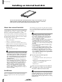 11
11
-
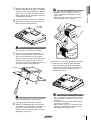 12
12
-
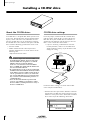 13
13
-
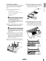 14
14
-
 15
15
-
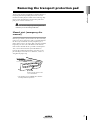 16
16
-
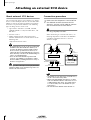 17
17
-
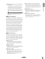 18
18
-
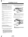 19
19
-
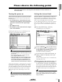 20
20
-
 21
21
-
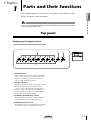 22
22
-
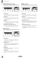 23
23
-
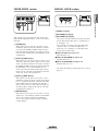 24
24
-
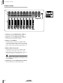 25
25
-
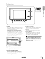 26
26
-
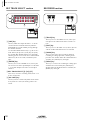 27
27
-
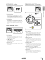 28
28
-
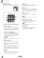 29
29
-
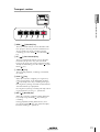 30
30
-
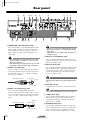 31
31
-
 32
32
-
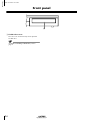 33
33
-
 34
34
-
 35
35
-
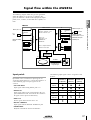 36
36
-
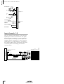 37
37
-
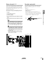 38
38
-
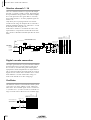 39
39
-
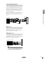 40
40
-
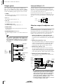 41
41
-
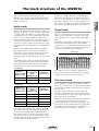 42
42
-
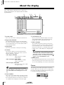 43
43
-
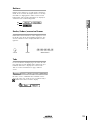 44
44
-
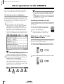 45
45
-
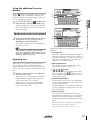 46
46
-
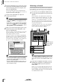 47
47
-
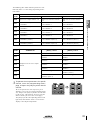 48
48
-
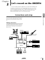 49
49
-
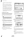 50
50
-
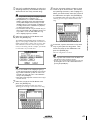 51
51
-
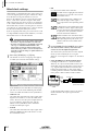 52
52
-
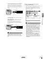 53
53
-
 54
54
-
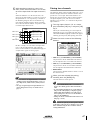 55
55
-
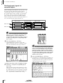 56
56
-
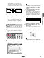 57
57
-
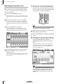 58
58
-
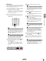 59
59
-
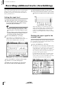 60
60
-
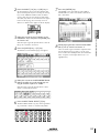 61
61
-
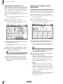 62
62
-
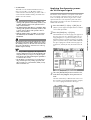 63
63
-
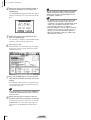 64
64
-
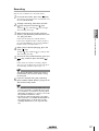 65
65
-
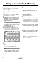 66
66
-
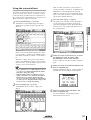 67
67
-
 68
68
-
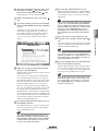 69
69
-
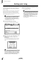 70
70
-
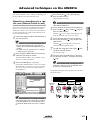 71
71
-
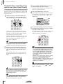 72
72
-
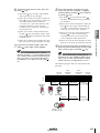 73
73
-
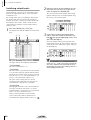 74
74
-
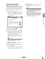 75
75
-
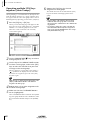 76
76
-
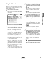 77
77
-
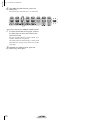 78
78
-
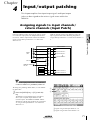 79
79
-
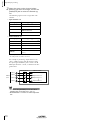 80
80
-
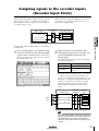 81
81
-
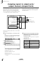 82
82
-
 83
83
-
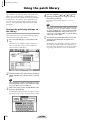 84
84
-
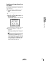 85
85
-
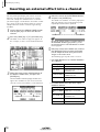 86
86
-
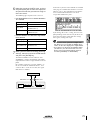 87
87
-
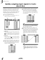 88
88
-
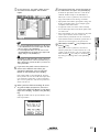 89
89
-
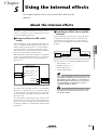 90
90
-
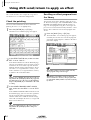 91
91
-
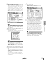 92
92
-
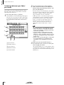 93
93
-
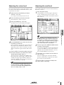 94
94
-
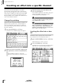 95
95
-
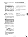 96
96
-
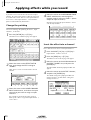 97
97
-
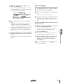 98
98
-
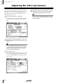 99
99
-
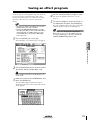 100
100
-
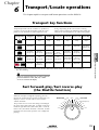 101
101
-
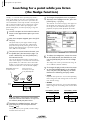 102
102
-
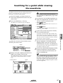 103
103
-
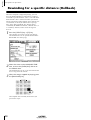 104
104
-
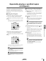 105
105
-
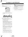 106
106
-
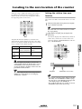 107
107
-
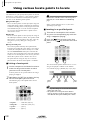 108
108
-
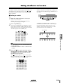 109
109
-
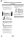 110
110
-
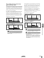 111
111
-
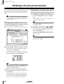 112
112
-
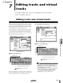 113
113
-
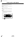 114
114
-
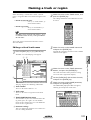 115
115
-
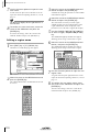 116
116
-
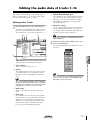 117
117
-
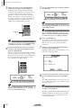 118
118
-
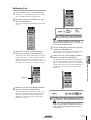 119
119
-
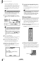 120
120
-
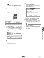 121
121
-
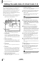 122
122
-
 123
123
-
 124
124
-
 125
125
-
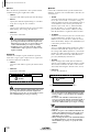 126
126
-
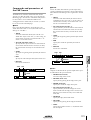 127
127
-
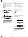 128
128
-
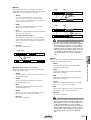 129
129
-
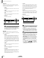 130
130
-
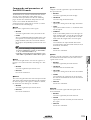 131
131
-
 132
132
-
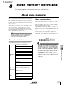 133
133
-
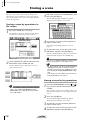 134
134
-
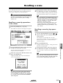 135
135
-
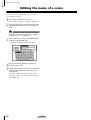 136
136
-
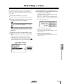 137
137
-
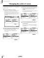 138
138
-
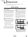 139
139
-
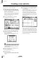 140
140
-
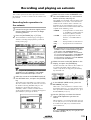 141
141
-
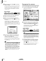 142
142
-
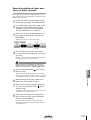 143
143
-
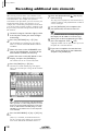 144
144
-
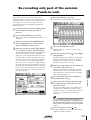 145
145
-
 146
146
-
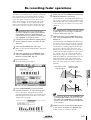 147
147
-
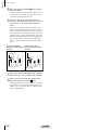 148
148
-
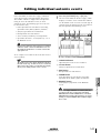 149
149
-
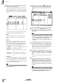 150
150
-
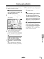 151
151
-
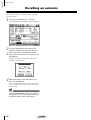 152
152
-
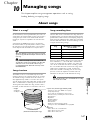 153
153
-
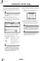 154
154
-
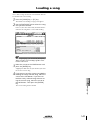 155
155
-
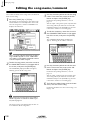 156
156
-
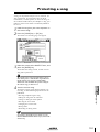 157
157
-
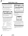 158
158
-
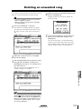 159
159
-
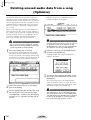 160
160
-
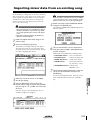 161
161
-
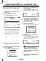 162
162
-
 163
163
-
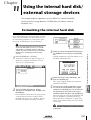 164
164
-
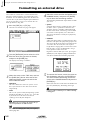 165
165
-
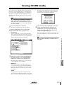 166
166
-
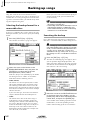 167
167
-
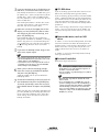 168
168
-
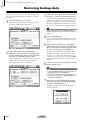 169
169
-
 170
170
-
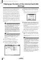 171
171
-
 172
172
-
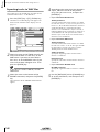 173
173
-
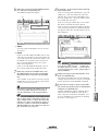 174
174
-
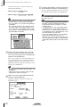 175
175
-
 176
176
-
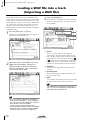 177
177
-
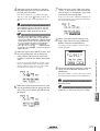 178
178
-
 179
179
-
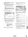 180
180
-
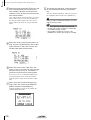 181
181
-
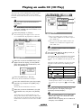 182
182
-
 183
183
-
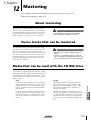 184
184
-
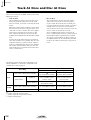 185
185
-
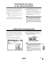 186
186
-
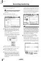 187
187
-
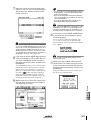 188
188
-
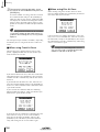 189
189
-
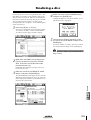 190
190
-
 191
191
-
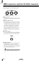 192
192
-
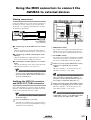 193
193
-
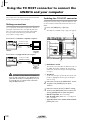 194
194
-
 195
195
-
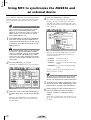 196
196
-
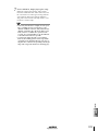 197
197
-
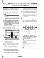 198
198
-
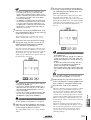 199
199
-
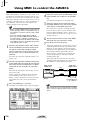 200
200
-
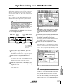 201
201
-
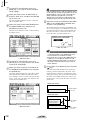 202
202
-
 203
203
-
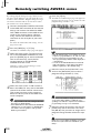 204
204
-
 205
205
-
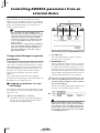 206
206
-
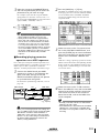 207
207
-
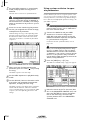 208
208
-
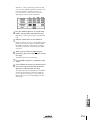 209
209
-
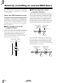 210
210
-
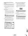 211
211
-
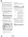 212
212
-
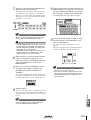 213
213
-
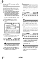 214
214
-
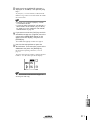 215
215
-
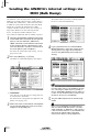 216
216
-
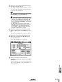 217
217
-
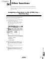 218
218
-
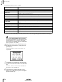 219
219
-
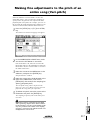 220
220
-
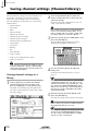 221
221
-
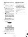 222
222
-
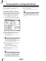 223
223
-
 224
224
-
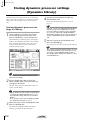 225
225
-
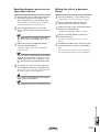 226
226
-
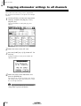 227
227
-
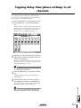 228
228
-
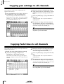 229
229
-
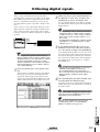 230
230
-
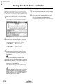 231
231
-
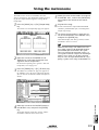 232
232
-
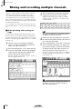 233
233
-
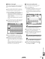 234
234
-
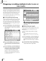 235
235
-
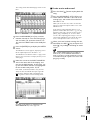 236
236
-
 237
237
-
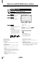 238
238
-
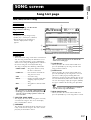 239
239
-
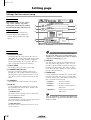 240
240
-
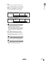 241
241
-
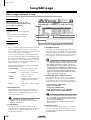 242
242
-
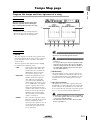 243
243
-
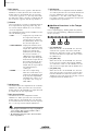 244
244
-
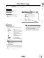 245
245
-
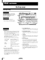 246
246
-
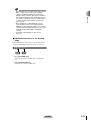 247
247
-
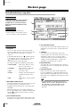 248
248
-
 249
249
-
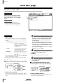 250
250
-
 251
251
-
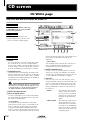 252
252
-
 253
253
-
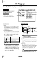 254
254
-
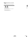 255
255
-
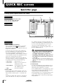 256
256
-
 257
257
-
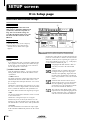 258
258
-
 259
259
-
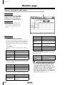 260
260
-
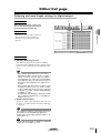 261
261
-
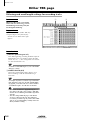 262
262
-
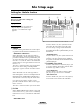 263
263
-
 264
264
-
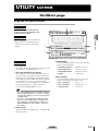 265
265
-
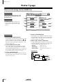 266
266
-
 267
267
-
 268
268
-
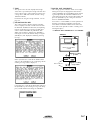 269
269
-
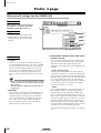 270
270
-
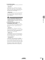 271
271
-
 272
272
-
 273
273
-
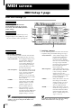 274
274
-
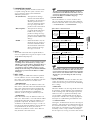 275
275
-
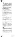 276
276
-
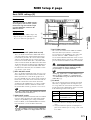 277
277
-
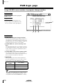 278
278
-
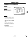 279
279
-
 280
280
-
 281
281
-
 282
282
-
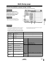 283
283
-
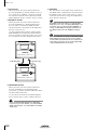 284
284
-
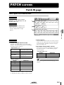 285
285
-
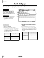 286
286
-
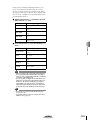 287
287
-
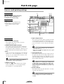 288
288
-
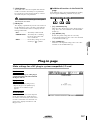 289
289
-
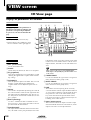 290
290
-
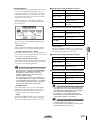 291
291
-
 292
292
-
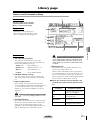 293
293
-
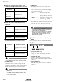 294
294
-
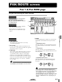 295
295
-
 296
296
-
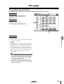 297
297
-
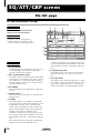 298
298
-
 299
299
-
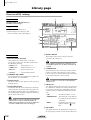 300
300
-
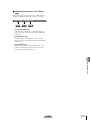 301
301
-
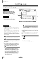 302
302
-
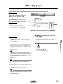 303
303
-
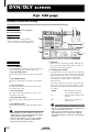 304
304
-
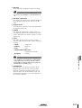 305
305
-
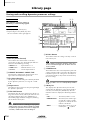 306
306
-
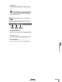 307
307
-
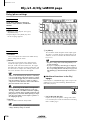 308
308
-
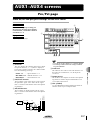 309
309
-
 310
310
-
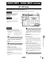 311
311
-
 312
312
-
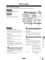 313
313
-
 314
314
-
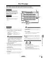 315
315
-
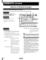 316
316
-
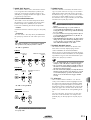 317
317
-
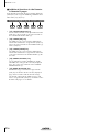 318
318
-
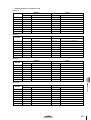 319
319
-
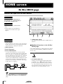 320
320
-
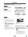 321
321
-
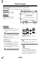 322
322
-
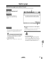 323
323
-
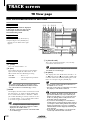 324
324
-
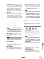 325
325
-
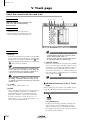 326
326
-
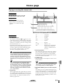 327
327
-
 328
328
-
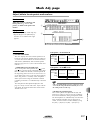 329
329
-
 330
330
-
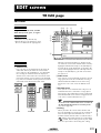 331
331
-
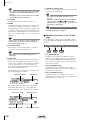 332
332
-
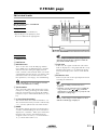 333
333
-
 334
334
-
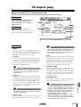 335
335
-
 336
336
-
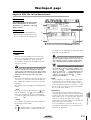 337
337
-
 338
338
-
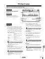 339
339
-
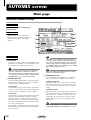 340
340
-
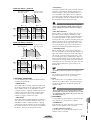 341
341
-
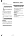 342
342
-
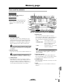 343
343
-
 344
344
-
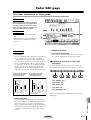 345
345
-
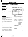 346
346
-
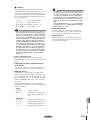 347
347
-
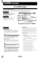 348
348
-
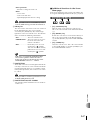 349
349
-
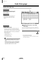 350
350
-
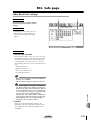 351
351
-
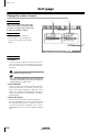 352
352
-
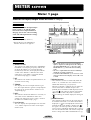 353
353
-
 354
354
-
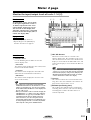 355
355
-
 356
356
-
 357
357
-
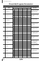 358
358
-
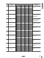 359
359
-
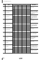 360
360
-
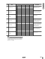 361
361
-
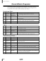 362
362
-
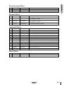 363
363
-
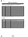 364
364
-
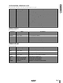 365
365
-
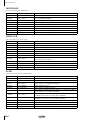 366
366
-
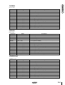 367
367
-
 368
368
-
 369
369
-
 370
370
-
 371
371
-
 372
372
-
 373
373
-
 374
374
-
 375
375
-
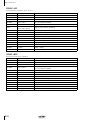 376
376
-
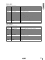 377
377
-
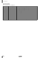 378
378
-
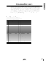 379
379
-
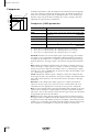 380
380
-
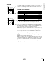 381
381
-
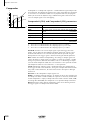 382
382
-
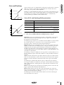 383
383
-
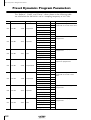 384
384
-
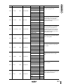 385
385
-
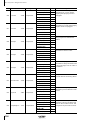 386
386
-
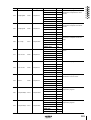 387
387
-
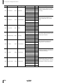 388
388
-
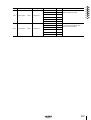 389
389
-
 390
390
-
 391
391
-
 392
392
-
 393
393
-
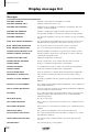 394
394
-
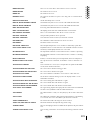 395
395
-
 396
396
-
 397
397
-
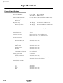 398
398
-
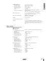 399
399
-
 400
400
-
 401
401
-
 402
402
-
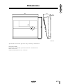 403
403
-
 404
404
-
 405
405
-
 406
406
-
 407
407
-
 408
408
-
 409
409
-
 410
410
-
 411
411
-
 412
412
-
 413
413
-
 414
414
-
 415
415
-
 416
416
-
 417
417
-
 418
418
-
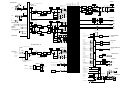 419
419
-
 420
420


Yamaha AW2816 Le manuel du propriétaire
- Catégorie
- Destinataire
- Taper
- Le manuel du propriétaire
- Ce manuel convient également à
dans d''autres langues
- italiano: Yamaha AW2816 Manuale del proprietario
- English: Yamaha AW2816 Owner's manual
- español: Yamaha AW2816 El manual del propietario
- Deutsch: Yamaha AW2816 Bedienungsanleitung
- русский: Yamaha AW2816 Инструкция по применению
- Nederlands: Yamaha AW2816 de handleiding
- português: Yamaha AW2816 Manual do proprietário
- dansk: Yamaha AW2816 Brugervejledning
- polski: Yamaha AW2816 Instrukcja obsługi
- čeština: Yamaha AW2816 Návod k obsluze
- svenska: Yamaha AW2816 Bruksanvisning
- Türkçe: Yamaha AW2816 El kitabı
- română: Yamaha AW2816 Manualul proprietarului
Documents connexes
-
Yamaha AW2400 Manuel utilisateur
-
-
-
-
-
-
-
-
Yamaha DM2000 Le manuel du propriétaire
-
Autres documents
-
Sony Recording Equipment MDM-X4 Manuel utilisateur
-
Sony CDP-D500 Manuel utilisateur
-
-
-
Peavey MIDI Master II Le manuel du propriétaire
-
-
Roland SPD-SX PRO Le manuel du propriétaire
-
Zoom R16 Manuel utilisateur
-
Ecler ALMA26 Manuel utilisateur
-
 Denon Professional DN 900R Guide de démarrage rapide
