
TEKNO 40 INSTALLATION
INSTRUCTIONS
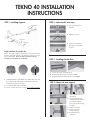
STEP 1 - Installing Supports
Height calculation for regular clips.
Add 1” to length of drapes, plus at least 1/2” clearence from
the fl oor. This measurement is the distance from fl oor to center
point of Back Plate.
Please note drapes should not touch rail,
install pin on hooks with this in consideration.
M-6 BOLT COVER PLATE INSIDE POST
1. Install Back Plate to wall. Make sure all M-6 bolts are level.
If you have a spliced track the Center Support must be
installed at the position of splice.
2. Cover Back Plate with Cover Plate.
3. Screw on Inside Post very securely. Do not leave any play.
STEP 2 - Splice track if necessary
CENTER
SUPPORT
SET SCREWS
SPLICE
STEP 3 - Installing Outside Posts
1. Join the track sections
together.
2. Tighten set screws.
3. Screw Center Support
directly into center hole
of Splice.
1. Loosen all screws on Outside Posts.
2. Slide Ouside Posts into back channel of Rail.
3. Align Outside Posts with Inside Posts from Step 1.
OUTSIDE POST
1
2 3
4
5
1. Slide Outside Posts over
Inside Posts.
2. Once all Outside Posts
including Center Supports
are in place, tighten
posts securely by turning
clockwise.
3. Tighten set screws.
4. Finished result for
Center Supports.
5. Finished result for
side posts.
STEP 4 - Mount rail onto supports
OUTSIDE POST
CARRIERS
COVER PLATE
INSIDE POST
BACK PLATE

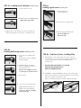
STEP 6b - Cord Draw Systems, Installing Pulley
1. Attach pulley to cord. Stretch pulley until cord is tight. It is
not necessary to use excessive tension. Mark spot with pencil
on wall or fl oor. Remove cords and install pulley then
re-install cords.
• THE PULLEY MUST BE INSTALLED. IT IS THE LAW.
FAILURE TO DO SO CAN RESULT IN
INJURY TO CHILDREN OR PETS!
2. IF NEEDED - To adjust CONTROL cord drop, pull cord through
master carrier until pulley is at desired height. Pull cord an extra
few inches and knot cord at proper spot.
When you install the pulley the cord will slide back into place.
STEP 5a - Installing carriers & baton (hand draw system)
1. Slide carriers into rail.
2. Attach fi nial onto rail. Do not over-
tighten as thread can strip.
3. Attach baton to side of drape you wish to operate from.
Either by clipping it into fi rst carrier or clicking into rail.
STEP 5b -
Installing ball-bearing carriers (hand draw system)
1. Loosen set-screw holding fi nial
hanger.
do not remove screw compleatly
from fi nal hanger.
2. Slide fi nial hanger outward to
allow for ball-bearing carriers to
be inserted into rail.
Note you must retighten set-screw
to create space to insert the carriers.
3. Insert carriers
4. Loosen set-screw and push fi nal
hanger back till fl ush with rail.
Tighten set-screw permanently.
Attach fi nial. Do not over-tighten
as thread can strip.
STEP 6a -
Installing regular carriers (corded system)
1. Remove plug next to
control mechanism.
2. Insert Carriers in track via slot.
3. Re-insert plug and attach fi nial.
Do not over-tighten as
thread can strip.

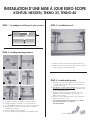
INSTALLATION D’UNE MISE À JOUR EURO-SCOPE
KONTUR, NEXGEN, TEKNO 25, TEKNO 40
ÉTAPE 3 - L’installation du rail
BOUCHON
ÉTAPE 1 - Assemblage du rail lorsque le splice est inclus
1. Installez les embouts et insérez suite les glissière dans le rail.
2. Attachez le lance-rideau à la première glissière sur le côté desiré
(ouverture à gauche ou à droite manuelle).
ÉTAPE 4 - Installation du la poulie
1. Déterminez si la corde sera du même côté que le lance-rideau.
Le côté du contrôle peut être changé en tirat la corde à travers
le contrôle du côté opposé.
2. Pour rails avec ouveture centrale seulement. Insérez le bouchon
de plastique au milieu du rail. Ce bouchon soutiendra la corde
lors de l’installation de la poulie.
3. Attachez les cordes à la poulie. Tirez la poulie pour créer
suffi samment de tension. Marquez le point sur le mur ou le
plancher avec un crayon.
4. Enlevez les cordes et attachez la poulie au mur ou au placher.
Installez de nouveau les cordes.
• La pouile drit être installée. C’est la loi. Ne pas s’y conformer
peut entreiner des blessures aux enfants ou
aux animaux fi miliers.
ÉTAPE 2 - Installing mounting hardware
1. Assemblez les attaches « assemblées » des tiges extérieures.
2. Attachez les attaches « assemblées » sur les tiges extérieures.
3. Assemblez partiellement l’attache “mise à jour” de la tige centrale.
4. Montez l’attache « centrale » sur la tige centrale et completez
l’assembiage. de l’attache.
5. Aperçu de l’attache centrale completée.
6. Toutes les attaches doivent être allignée pour l’installation du rail.
1
2
3 4
5
6
-
 1
1
-
 2
2
-
 3
3


dans d''autres langues
Autres documents
-
Art Decor I-04-0072-WF/VB Mode d'emploi
-
 Lutron Electronics Sivoia QS Guide d'installation
-
Hobie FX One Assembly Manual
-
ROBBE Valdivia Assembly And Operating Instructions Manual
-
Craftsman 139.18595 Manuel utilisateur
-
Harris XL-185M Guide d'installation
-
Fortress Technologies PURE VIEW GLASS BALUSTER AL13 HOME Installation Instructions Manual
-
Swing-N-Slide Playsets 6039 Mode d'emploi
-
Chamberlain 7220 Manuel utilisateur
-
