INSTRUCTION MANUAL
ALUMINUM SITE-RITE
®
HAND BENDERS
840A, 841A, 842A, 843A,
840AH, 841AH and 842AH
AND
IRON SITE-RITE
®
HAND BENDERS
840F, 841F, 842F, 843F,
840FH, 841FH, and 842FH
Read and understand this material
before operating or servicing this
equipment. Failure to understand how to
safely operate this tool could result in an
accident causing serious injury or death.
52034125 REV 1 © 2019 Greenlee Tools, Inc. 01/19

SITE-RITE
®
Hand Benders
Greenlee Tools, Inc.
2
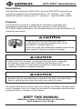
Description
The Greenlee aluminum SITE-RITE
®
and iron SITE-RITE
®
benders are
manually powered tools intended to bend 1/2" through 1-1/4" EMT
(electrical metallic tubing) and 1/2" through 1" rigid and IMC conduit.
Purpose
This instruction manual is intended to familiarize operators and
maintenance personnel with the safe operation of the Greenlee
SITE-RITE
®
Manual Benders. This manual should be kept available to all
operating personnel.
A person who has not read and does not
understand all operating instructions is not
qualified to operate this tool.
Failure to read and understand safety instructions
may result in injury or property damage.
Inspect the tool for wear or damage. Replace worn, damaged,
or missing components with Greenlee replacement parts.
A worn, damaged, or improperly assembled component may fail,
resulting in injury or property damage.
Use this tool for manufacturer’s intended use only. Use other than
that for which the tool was intended may result in injury.
All specifications are nominal and may change as design improvements
occur. Greenlee Tools, Inc. shall not be liable for damages resulting from
misapplication or misuse of its products.
KEEP THIS MANUAL
Additional copies of this manual are available
upon request at no charge.

SITE-RITE
®
Hand Benders
4455 Boeing Dr. • Rockford, IL 61109-2988 USA • 815-397-7070
3
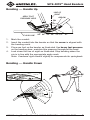
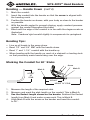
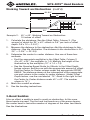
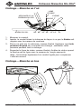
Bending — Handle Up
LINE OF
SIGHT
PIN
ARROW
90° 60° 45° 30° 22-1/2° 10°
APPLY FOOT
PRESSURE HERE
FLOOR LINE
45°
1. Mark the conduit.
2. Insert the conduit into the bender so that the arrow is aligned with
the bending mark.
3.
Place one foot on the bender as illustrated. Use heavy foot pressure
on the bending shoe; maintain this pressure throughout the bend.
4. Look down the line of sight as illustrated. Stop bending when the
pin is in line with the appropriate angle mark.
Note: Overbend rigid conduit slightly to compensate for springback.
Bending — Handle Down
10°
22
1
/2°
30°
45°
60°
90°

SITE-RITE
®
Hand Benders
Greenlee Tools, Inc.
4
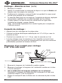
Bending — Handle Down (cont’d)
1. Mark the conduit.
2. Insert the conduit into the bender so that the arrow is aligned with
the bending mark.
3. Position the bender as shown, with your body as close to the bender
as possible.
4. With the handle angled to prevent slipping, apply constant pressure
against the conduit throughout the bend.
5. Bend until the edge of the conduit is in line with the degree scale as
illustrated.
Note: Overbend rigid conduit slightly to compensate for springback.
Bending Tips:
• Line up all bends in the same plane.
• Bend 1/2" and 3/4" EMT with the handle down.
• Bend 1" and 1-1/4" conduit with the handle up.
• When bending with the handle up, work at a stairwell or loading dock
so that previously made bends hang over the edge.
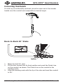
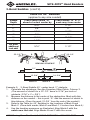
Marking the Conduit for 90° Stubs
Mark A
Mark B
Arrow
DEDUCT
HEIGHT OF STUB
HEIGHT
OF
STUB
1. Measure the length of the required stub.
2. Measure and mark the stub length on the conduit. This is Mark A.
3. See the Deduct length shown on the bender. Subtract the Deduct
length from Mark A and make a new mark. This is Mark B.
4. Align Mark B with the arrow on the bender and bend the conduit
to 90°.

SITE-RITE
®
Hand Benders
4455 Boeing Dr. • Rockford, IL 61109-2988 USA • 815-397-7070
5
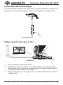
Correcting Overbends
If a stub-up is accidentally overbent, place the open end of the bender
handle over the conduit and manipulate to desired angle.
Back-to-Back 90° Stubs
FINISH LINE
MARK
MARK
1. Make the first 90° stub.
2. Fit the bent conduit into its final position and mark the Finish Line
on the conduit, as shown. The Finish Line on the conduit is the
bending mark.
3. Align the bending mark with the tip of the star and bend the conduit
to 90°.

SITE-RITE
®
Hand Benders
Greenlee Tools, Inc.
6
Offset Bends
An offset is used to re-route the conduit to avoid an obstruction.
An offset consists of two equal opposing bends.
Two factors must be considered when selecting the offset angle. First, a
steeper bend angle will require more pulling force. Second, a shallower
bend angle will require more space.
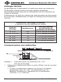
Greenlee Offset Table
(applies to any size conduit)
Offset Angle Multiplier
Shrink Per Inch
of Offset Depth
10° x 10° 6.0 1/16" per inch
22-1/2° x 22-1/2° 2.6 3/16" per inch
30° x 30° 2.0 1/4" per inch
45° x 45° 1.4 3/8" per inch
60° x 60° 1.2 1/2" per inch
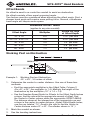
Working Past an Obstruction
OBSTRUCTION
14"8"
8"
10" DEPTH
MARK A
MARK B
45°
Example 1: Working Past an Obstruction
45° x 45°, 10 inches of offset
1. Determine the center-to-center distance. Use one of these two
methods:
• Find the appropriate multiplier in the Offset Table, Column 2.
(For 45° x 45°, the multiplier is 1.4). Multiply the height of the
obstruction by the multiplier (10" x 1.4 = 14).
•
See the Greenlee Speed Guide for Offsets. In the Offset Depth Inches
column, find the row with the appropriate amount of offset. Find
the Center-to-Center column under the appropriate OFFSET ANGLE.
The distance shown at the intersection of the appropriate row and
column is the center-to-center distance. (Under Offset Depth Inches,
see the row labeled “10”. Read to the right to find the Center-to-
Center distance under 45° x 45°. The number shown is 14".)
2. Mark the conduit as shown.
3. See the bending instructions.

SITE-RITE
®
Hand Benders
4455 Boeing Dr. • Rockford, IL 61109-2988 USA • 815-397-7070
7
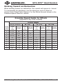
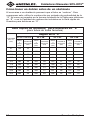
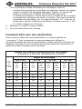
Working Toward an Obstruction
When working toward an obstruction, the conduit will appear to “shrink.”
To compensate for shrinkage, use the shrink per inch of offset as
shown in the Offset Table, Column 3 or the Shrink Amount shown in the
Greenlee Speed Guide for Offsets.
Greenlee Speed Guide for Offsets
(applies to any size conduit)
Offset
Depth
Inches
Offset Angle
22-1/2° x 22-1/2°
30° x 30° 45° x 45° 60° x 60°
Center
-to-
Center
Shrink
Amount
Center
-to-
Center
Shrink
Amount
Center
-to-
Center
Shrink
Amount
Center
-to-
Center
Shrink
Amount
2 5-1/4" 3/8"
3 7-3/4" 9/16" 6" 3/4"
4 10-1/2" 3/4" 8" 1"
5 13" 15/16" 10" 1-1/4" 7" 1-7/8"
6 15-1/2" 1-1/8" 12" 1-1/2" 8-1/2" 2-1/4" 7-1/4" 3"
7 18-1/4"
1-5/16"
14" 1-3/4" 9-3/4" 2-5/8" 8-3/8" 3-1/2"
8 20-3/4" 1-1/2" 16" 2" 11-1/4" 3" 9-5/8" 4"
9 23-1/2" 1-3/4" 18" 2-1/4" 12-1/2" 3-3/8"
10-7/8"
4-1/2"
10 26" 1-7/8" 20" 2-1/2" 14" 3-3/4 12" 5"

SITE-RITE
®
Hand Benders
Greenlee Tools, Inc.
8
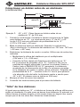
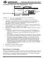
Working Toward an Obstruction (cont’d)
OBSTRUCTION
14"
33-3/4"
45°
10" DEPTH
MARK B
MARK A
30"
Example 2: 45° x 45°, Working Toward an Obstruction
10 inches of offset
1. Calculate the shrinkage. See the Offset Table, Column 3. (The
amount of shrink for 45° x 45° offsets is 3/8" per inch of offset
depth. 3/8 x 10 = 3-3/4")
2. Measure the distance to the obstruction. Add the shrinkage to this
distance. (See the illustration. The distance to the obstruction is 30".
30" + 3-3/4" = 33-3/4)
3. Determine the center-to-center distance. Use one of these two
methods:
• Find the appropriate multiplier in the Offset Table, Column 2.
(For 45° x 45°, the multiplier is 1.4). Multiply the height of the
obstruction by the multiplier (10" x 1.4 = 14).
• See the Greenlee Speed Guide for Offsets. In the Offset Depth
Inches column, find the row with the appropriate amount of offset.
Find the Center-to-Center column under the appropriate OFFSET
ANGLE. The distance shown at the intersection of the appropriate
row and column is the center-to-center distance. (Under Offset
Depth Inches, see the row labeled “10”. Read to the right to find
the Center-to-Center distance under 45° x 45°. The number
shown is 14".)
4. Mark the conduit as shown.
5. See the bending instructions.
3-Bend Saddles
Like an offset, a saddle is used to avoid an obstruction. In this case,
three bends are used. The first and last bends are of the same degree;
the center bend is twice the number of degrees of the other two bends.
See the illustrations.

SITE-RITE
®
Hand Benders
4455 Boeing Dr. • Rockford, IL 61109-2988 USA • 815-397-7070
9
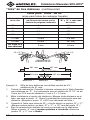
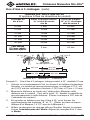
3-Bend Saddles (cont’d)
Table for 45° Saddles
(applies to any size conduit)
Saddle
Depth
Place center Mark “A”
ahead of actual center by
Place Marks “B” & “C”
each way from center
1" 3/16" 2-1/2"
2" 3/8" 5"
3" 9/16" 7-1/2"
4" 3/4" 10"
5" 15/16" 12-1/2"
6" 1-1/8" 15"
For each
additional
inch add:
3/16" 2-1/2"
A 45°
BENDING SEQUENCE
B
C
22-1/2°
22-1/2°
2" DIAMETER
15"
5"5"
18-3/8"15-3/8"
MARK B MARK A MARK C
Example 3: 3-Bend Saddle 45° center bend, 2" obstacle
1. Calculate the shrinkage. See the Greenlee Offset Table, Column 3.
(The amount of shrink for a 22-1/2° bend is 3/16" per inch of
obstacle. 3/16" x 2 = 3/8").
2.
Measure the distance to the center of the obstruction. Mark with this
distance on the conduit – this is point “A”. Add the amount of shrink to
this distance. (Place the mark 15-3/8" from the end of the conduit.)
3. Refer to the Table for 45° Saddles for the locations of Mark B and
Mark C. (Place both marks, Mark B and Mark C, 5 inches from Mark A.)
4. Use the bending sequence as illustrated. Align Mark A with the
notch near the star. Align Marks B and C with the arrow.

MANUAL DE INSTRUCCIONES
DOBLADORAS MANUALES
SITE-RITE
®
DE ALUMINIO
840A, 841A, 842A, 843A,
840AH, 841AH and 842AH
Y
DOBLADORAS MANUALES
SITE-RITE
®
DE HIERRO
840F, 841F, 842F, 843F,
840FH, 841FH, and 842FH
Lea y entienda este documento antes
de manejar o dar servicio a este equipo.
Utilizarlo sin comprender cómo manejarlo
de manera segura podría ocasionar un
accidente y como resultado de éste,
graves lesiones o incluso la muerte.
52034125 REV 1 © 2019 Greenlee Tools, Inc. 01/19

Dobladoras Manuales SITE-RITE
®
4455 Boeing Dr. • Rockford, IL 61109-2988 USA • 815-397-7070
11
Descripción
Las dobladoras SITE-RITE
®
de aluminio y SITE-RITE
®
de hierro Greenlee
son herramientas manuales diseñadas para doblar tubería metálica eléc-
trica (EMT) de 1/2 pulg. a 1-1/4 pulg. y conducto metálico intermedio
(IMC) y rígido de 1/2 pulg. a 1 pulg.
Propósito de este manual
Este manual de instrucciones tiene como propósito familiarizar a los
operadores y al personal de mantenimiento con el manejo seguro de
las Dobladoras manuales SITE-RITE
®
de Greenlee, y deberá, por tanto,
mantenerse siempre al alcance de dicho personal.
La persona que no haya leído o no comprenda
estas instrucciones de operación no estará
calificada para manejar esta herramienta.
De no leerse y entenderse estas instrucciones
podrían ocurrir lesiones personales o incluso
la muerte.
Inspeccione la herramienta y verifique que no presenten averías o
desgastes. Reemplace todas las partes averiadas o desgastadas. Si
se utiliza una herramienta averiada o si no se la ensambla bien, ésta
podría fallar, ocasionando lesiones personales o daños materiales.
Utilice esta herramienta únicamente para el uso especificado por el
fabricante; de utilizarla para otro propósito podrían sufrirse lesiones.
CONSERVE ESTE MANUAL
Puede solicitar copias adicionales de este manual
de manera gratuita, previa solicitud.

Dobladoras Manuales SITE-RITE
®
12
Greenlee Tools, Inc.
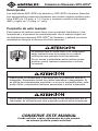
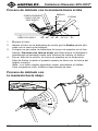
Proceso de doblado con la manivela hacia arriba
FLECHA
90° 60° 45° 30° 22-1/2° 10°
45°
MIRILLA
PASADOR
EJERZA PRESIÓN
CON EL PIE EN
ESTE PUNTO
LÍNEA DEL SUELO
1. Marque el tubo.
2. Inserte el tubo en la dobladora de modo que la flecha quede alin-
eada con la marca de doblado.
3. Coloque un pie sobre la dobladora tal como se muestra en la ilus-
tración. Presione con fuerza el pie que tiene sobre la dobladora;
manténgalo presionado hasta que termine de realizar el doblez.
4. Fije su vista en la mirilla, tal como se muestra en la ilustración.
Deje de doblar cuando el pasador quede en línea con la marca del
ángulo correcto.
Nota: Los tubos rígidos opondrán mayor resistencia al doblez.
Para compensar esto, dóblelos ligeramente de más.
Proceso de doblado con
la manivela hacia abajo
10°
22
1
/2°
30°
45°
60°
90°

Dobladoras Manuales SITE-RITE
®
4455 Boeing Dr. • Rockford, IL 61109-2988 USA • 815-397-7070
13
Proceso de doblado con la manivela hacia abajo
(continuación)
1. Marque el tubo.
2. Inserte el tubo en la dobladora de modo que la flecha quede
alineada con la marca de doblado.
3. Coloque la dobladora tal como se muestra en la ilustración;
acérquela lo más posible a su cuerpo.
4. Con la manivela en ángulo a fin de evitar que se le resbale, aplique
una presión constante sobre el tubo hasta que acabe de realizar el
doblez.
5. Doble hasta que el borde del tubo quede en línea con la escala de
grados tal como se muestra en la ilustración.
Nota: Los tubos rígidos opondrán mayor resistencia al doblez.
Para compensar esto, dóblelos ligeramente de más.
Sugerencias para realizar los dobleces:
• Alinee todos los dobleces en el mismo plano.
• Doble las tuberías metálicas para aplicaciones eléctricas con la
manivela hacia abajo.
•
Doble los tubos de 1 y 1-1/4 de pulg. con la manivela hacia arriba.
• Cuando realice dobleces con la manivela hacia arriba, hágalo en
una escalera o en un muelle de carga de modo que los dobleces ya
terminados cuelguen por el borde del escalón o del muelle.
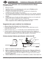
Cómo marcar tubos para hacer codos de 90°
Marca A
Marca B
Flecha
SUBSTRAIGA
ALTURA DEL CODO
ALTURA
DEL
CODO
1. Mida la longitud necesaria del codo.
2. Mida y marque la longitud del codo en el tubo. Ésta es la Marca A.
3. Vea la longitud de Deducción mostrada en la dobladora. Reste
la longitud de Deducción de la Marca A y haga una marca nueva.
Ésta es la Marca B.
4.
Alinee la Marca B con la flecha en la dobladora y doble el tubo hasta 90°.

Dobladoras Manuales SITE-RITE
®
14
Greenlee Tools, Inc.
Corrección de doblez excesivo
Si accidentalmente, se dobla demasiado un codo, coloque el extremo
abierto de la manivela de la dobladora sobre el tubo y manipule éste
hasta el ángulo deseado.
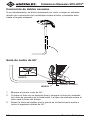
Serie de codos de 90°
MARCA
MARCA
LÍNEA DE ACABADO
1. Marque el primer codo de 90°.
2. Coloque el tubo en su posición final y marque la línea de acabado
tal como se muestra en la ilustración. La línea de acabado sobre el
tubo será la línea del doblez.
3. Alinee la línea del doblez con la punta de la flecha hacia arriba e
inicie el siguiente doblez de 90°.

Dobladoras Manuales SITE-RITE
®
4455 Boeing Dr. • Rockford, IL 61109-2988 USA • 815-397-7070
15
Dobleces en “S”
Un doblez en “S” sirve para volver a cambiar la dirección del tubo a fin de
evitar algún obstáculo. Una “S” consiste en dos dobleces opuestos idénticos.
Al seleccionar el ángulo para la “S” es necesario tomar en cuenta dos
factores. Primero, para hacer un doblez con un ángulo más profundo se
requerirá mayor fuerza. Segundo, para hacer un doblez con un ángulo
menos profundo se requerirá más espacio.
Tabla de Greenlee
®
para dobleces en “S”
(para tubos de cualquier tamaño)
Ángulo de la “S” Multiplicador Contracción por milímetro
de profundidad de la “S”
10° x 10° 6,0 0,0625 mm por milímetro
22-1/2° x 22-1/2° 2,6 0,1875 mm por milímetro
30° x 30° 2,0 0,25 mm por milímetro
45° x 45° 1,4 0,375 mm por milímetro
60° x 60° 1,2 0,5 mm por milímetro
Cómo hacer un doblez después de un obstáculo
OBSTÁCULO
14"
MARCA A
MARCA B
45°
356 mm
203 mm
203 mm
254 mm de
PROFUNDIDAD
Ejemplo 1: Cómo hacer un doblez después de un obstáculo
45° x 45°, “S” de 254 mm
1.
Determine la distancia centro a centro. Utilice uno de estos dos métodos.
• Halle el multiplicador correspondiente en la segunda columna de
la Tabla para dobleces en “S”. (El multiplicador para 45° x 45°
es 1,4). Multiplique la altura del obstáculo por el multiplicador
(254 mm x 1,4 = 356 mm).
•
Consulte la Guía rápida de Greenlee para dobleces en “S”. En la
columna de pulgadas de la “S”, localice la fila con la cantidad de
ángulo apropiada. Localice la columna Centro a Centro, bajo el
ÁNGULO DE LA “S” apropiado. La distancia mostrada en la
inter sección de la fila y la columna correctas es la distancia de centro
a centro. (En la columna “Profundidad de la ‘S’”, localice la fila 10.
Lea lo que aparece a la derecha a fin de hallar la distancia centro a
centro para 45° x 45°. El número que se indica es 356 mm).
2. Marque el tubo tal como se muestra.
3. Consulte las instrucciones para el proceso de doblado.

Dobladoras Manuales SITE-RITE
®
16
Greenlee Tools, Inc.
Cómo hacer un doblez antes de un obstáculo
Al acercarse a un obstáculo parecerá que el tubo se “contrae”. Para
compensar esto, utilice la contracción por pulgada de profundidad de la
“S” tal como se muestra en la tercera columna de la Tabla para dobleces
en “S”, o en la Cantidad de contracción incluidas en la Guía rápida de
Greenlee para dobleces en “S”.
Guía rápida de Greenlee
®
para dobleces en “S”
(para tubos de todos tamaños)
Profundidad
de la “S”
(mm)
Ángulo de la “S”
22-1/2° x 22-1/2°
30° x 30° 45° x 45° 60° x 60°
Centro
a
centro
(mm)
Cantidad de
contracción
(mm)
Centro
a
centro
(mm)
Cantidad de
contracción
(mm)
Centro
a
centro
(mm)
Cantidad de
contracción
(mm)
Centro
a
centro
(mm)
Cantidad de
contracción
(mm)
51 133 10
76 198 14 152 19
102 265 19 204 26
127 330 24 254 32 178 48
152 395 29 304 38 213 57 182 76
178 463 33 356 45 249 67 214 89
203 528 38 406 51 284 76 244 102
229 595 43 458 57 321 86 275 115
254 660 48 508 64 356 95 305 127

Dobladoras Manuales SITE-RITE
®
4455 Boeing Dr. • Rockford, IL 61109-2988 USA • 815-397-7070
17
Cómo hacer un doblez antes de un obstáculo
(continuación)
45°
MARCA B
MARCA A
OBSTÁCULO
356 mm
857 mm
254 mm
DE PROFUNDIDAD
762 mm
Ejemplo 2: 45° x 45°, Cómo hacer un doblez antes de un
obstáculo “S” de 254 mm
1. Calcule la contracción. Consulte la tercera columna de la Tabla
para dobleces en “S”. (La contracción para “S” de 45° x 45°
es de 0,375 mm por milímetro de profundidad de la “S”.
0,375 x 254 mm = 95 mm).
2. Mida la distancia hasta el obstáculo. Súmele la contracción.
(Vea la ilustración. La distancia del obstáculo es 762 mm. 762 mm
+ 95 mm = 857 mm).
3. Establezca la distancia de centro a centro. Utilice uno de estos dos
métodos.
• Multiplique la altura del obstáculo por el multiplicador.
(254 mm x 1,4 = 356 mm)
• Consulte la Guía rápida de Greenlee para dobleces en “S”.
En la columna de pulgadas de la “S”, localice la fila con la
cantidad de ángulo apropiada. Localice la columna Centro a
Centro, bajo el ÁNGULO DE LA “S” apropiado. La distancia
mostrada en la intersección de la fila y la columna correctas
es la distancia de centro a centro. (En la columna “Pulgadas de
profundidad de la ‘S’ “, localice la fila 10. Lea lo que aparece
a la derecha a fin de hallar la distancia centro a centro para
45° x 45°. El número que se indica es 356 mm).
4. Marque el tubo tal como se muestra.
5. Consulte las instrucciones para el proceso de doblado.
“Silla” de tres dobleces
Al igual que un doblez en “S”, el doblez en forma de silla se utiliza para
evitar un obstáculo. En este caso se hacen tres dobleces. El primero y el
último tienen el mismo ángulo; el del centro tiene un ángulo dos veces
mayor que el de los otros dos. Véase las ilustraciones.

Dobladoras Manuales SITE-RITE
®
18
Greenlee Tools, Inc.
“Silla” de tres dobleces (continuación)
Tabla para “sillas” de 45°
(sirve para tubos de cualquier tamaño)
Profundidad
de la silla
Coloque la marca de centro “A”
por delante del centro real el
número de pulgadas indicadas
Coloque las marcas
“B” y “C” a cada lado
del centro
25 mm 5 mm 64 mm
51 mm 10 mm 127 mm
76 mm 14 mm 191 mm
101 mm 19 mm 254 mm
127 mm 24 mm 318 mm
152 mm 29 mm 381 mm
Por cada 25.4
mm adicional
5 mm 64 mm
SECUENCIA DE
DOBLADO DE 45°
B
C
22-1/2°
22-1/2°
381 mm 457 mm
391 mm
51 mm
DE DIÁMETRO
467 mm
127
mm
127
mm
MARCA AMARCA B MARCA C
Ejemplo 3: Silla de tres dobleces con doblez central de 45°;
obstáculo de 51 mm
1. Calcule la contracción. Consulte la tercera columna de la Tabla Greenlee
para dobleces en “S”. (La contracción para un doblez de 22-1/2° es de
5 mm por 25.4 mm de obstáculo. 5 mm x 2 = 10 mm).
2. Mida la distancia al centro del obstáculo. Marque dicha distancia en el
tubo, ese será el punto “A”. Sume la cantidad de contracción para esa
distancia. (Marque el punto “A” a 391 mm del borde del tubo.)
3. Consulte la Tabla para sillas de 45°, a fin de ubicar los puntos “B” y “C”.
(Marque ambos puntos, es decir “B” y “C”, a 127 mm del punto “A”.)
4. Siga la secuencia de doblado tal como se muestra en la ilustración.
Alinee el punto “A” con la muesca próxima a la estrella. Alinee los
puntos “B” y “C” con la flecha.

MANUEL D’INSTRUCTIONS
CINTREUSES MANUELLES
SITE-RITE
®
EN ALUMINIUM
840A, 841A, 842A, 843A,
840AH, 841AH and 842AH
ET
CINTREUSES MANUELLES
SITE-RITE
®
EN FER
840F, 841F, 842F, 843F,
840FH, 841FH, and 842FH
Lire et assimiler ces instructions avant
d’utiliser cet appareil ou d’en faire le
service. Négliger de comprendre
comment utiliser cet outil sans danger,
peut résulter en un accident causant des
blessures graves ou même la mort.
52034125 REV 1 © 2019 Greenlee Tools, Inc. 01/19

Cintreuses Manuelles Site-Rite
®
20
Greenlee Tools, Inc.
Description
Les cintreuses SITE-RITE
®
en aluminium et en fer sont des outils
actionnés manuellement et conçus pour plier des tubes EMT de
1/2 po à 1-1/4 po (tubage métallique électrique) et des tubes IMC et
rigides de 1/2 po à 1 po.
Objet
Ce manuel d’instructions est prévu pour familiariser les utilisateurs
et le personnel d’entretien avec un usage sans danger des cintreuses
manuelles SITE-RITE
®
de Greenlee. Ce manuel doit rester à la disposition
de tous le personnel utilisateur.
Une personne qui n’a pas lu et ne comprend
pas toutes les instructions d’utilisation n’est pas
qualifiée pour utiliser cet outil.
Négliger de lire et de comprendre les instructions
de sécurité peut résulter en blessures ou en mort.
Vérifier si l’outil n’est pas usé ou endommagé. Remplacer les
composants usés, endommagés ou manquants par des pièces de
remplacement Greenlee. Un composant usé, endommagé ou mal
monté peut entraîner une défaillance et causer des blessures ou des
dommages matériels.
Cet outil ne doit être utilisé que pour l’usage prévu par le fabri-
cant. D’autres usages pour lesquels l’outil n’est pas prévu peuvent
entraîner des blessures.
CONSERVEZ CE MANUEL
Des exemplaires supplémentaires de ce manuel sont
disponibles sur demande et sans frais.
La page est en cours de chargement...
La page est en cours de chargement...
La page est en cours de chargement...
La page est en cours de chargement...
La page est en cours de chargement...
La page est en cours de chargement...
La page est en cours de chargement...
La page est en cours de chargement...
-
 1
1
-
 2
2
-
 3
3
-
 4
4
-
 5
5
-
 6
6
-
 7
7
-
 8
8
-
 9
9
-
 10
10
-
 11
11
-
 12
12
-
 13
13
-
 14
14
-
 15
15
-
 16
16
-
 17
17
-
 18
18
-
 19
19
-
 20
20
-
 21
21
-
 22
22
-
 23
23
-
 24
24
-
 25
25
-
 26
26
-
 27
27
-
 28
28


Greenlee Site-Rite Hand Benders, Aluminum, Iron Manuel utilisateur
- Taper
- Manuel utilisateur
- Ce manuel convient également à
dans d''autres langues
Documents connexes
-
Greenlee 884 & 885 Hydraulic Bender Manual Manuel utilisateur
-
-
-
-
-
-
-