
INSTRUCTION MANUAL
881 and 881CT Cam Track
®
Hydraulic Benders
and 1813 Bending Table
99980711 © 2020 Greenlee Tools, Inc. IM 981 REV 20 03/20
Read and understand all of the instructions and
safety information in this manual before operating
or servicing this tool.
Register this product at www.greenlee.com
Español ............... 33
Français .............. 65

881 and 881CT Hydraulic Benders
Greenlee Tools, Inc. 4455 Boeing Dr. • Rockford, IL 61109-2988 USA • 815-397-7070
2
Description
The 881 and 881CT Cam Track
®
Hydraulic Benders
are intended to bend rigid conduit, IMC (intermediate
metallic conduit), EMT (electrical metallic conduit), and
Schedule 40 pipe. Bending shoes, follow bars, and
saddles are available for bending 2-1/2" through 4"
conduit or pipe.
The bender is to be coupled to any Greenlee hydraulic
pump capable of developing 10,000 psi with a usable oil
volume of 6 quarts or more. Suggested pumps include
the following models:
• Electric Pump (120 volt): 960 SAPS, 980
• Electric Pump (220 volt): 980-22FS, 980-22PS
Safety
Safety is essential in the use and maintenance of
Greenlee tools and equipment. This instruction manual
and any markings on the tool provide information for
avoiding hazards and unsafe practices related to the
use of this tool. Observe all of the safety information
provided.
Purpose of this Manual
This instruction manual is intended to familiarize opera-
tors and maintenance personnel with the safe operation
and maintenance procedures for the Greenlee 881 and
881CT Cam Track
®
Hydraulic Benders.
Keep this manual available to all personnel.
Replacement manuals are available upon request at no
charge at www.greenlee.com.
All specications are nominal and may change as design
improvements occur. Greenlee Tools, Inc. shall not be liable for
damages resulting from misapplication or misuse of its products.
Cam Track is a registered trademark of Greenlee Tools, Inc.
KEEP THIS MANUAL
Table of Contents
Description .................................................................... 2
Safety ............................................................................ 2
Purpose of this Manual ................................................. 2
Important Safety Information .....................................3–4
Identication—Major Components ............................... 5
Assembly and Operation Instructions ......................6–20
881 and 881CT Floor Operation .............................6–9
881 and 881CT with 1813 Bending Table ........... 10–20
Glossary of Bending Terms ......................................... 21
Laying Out One-Shot 90° Bends ................................. 22
Table 2—Deduct, Stub Dimensions, and
Minimum Distance from End of Conduit ..................... 22
Table 3—Ram Travel .................................................... 23
Table 4—Laying Out Two-Shot 90° Bends
for 3-1/2" and 4" Conduit (881 only) ........................... 24
Laying Out Bends ................................................... 25–27
Stubs ........................................................................ 25
Offsets ................................................................25–26
Saddles ...............................................................26–27
U-Bends ................................................................... 27
Special Bending Information Chart ........................28–31
Troubleshooting ........................................................... 32
Spanish ...................................................................33–64
French ....................................................................65–96
Illustrations and Parts Lists ..................................97–104

881 and 881CT Hydraulic Benders
Greenlee Tools, Inc. 4455 Boeing Dr. • Rockford, IL 61109-2988 USA • 815-397-7070
3
IMPORTANT SAFETY INFORMATION
SAFETY
ALERT
SYMBOL
This symbol is used to call your attention to hazards
or unsafe practices which could result in an injury or
property damage. The signal word, dened below,
indicates the severity of the hazard. The message
after the signal word provides information for pre-
venting or avoiding the hazard.
Immediate hazards which, if not avoided, WILL result
in severe injury or death.
Hazards which, if not avoided, COULD result in
severe injury or death.
Hazards or unsafe practices which, if not avoided,
MAY result in injury or property damage.
Read and understand all of the
instructions and safety information
in this manual before operating or
servicing this tool.
Failure to observe this warning could
result in severe injury or death.
Use only Greenlee shoes and components when
operating this bender. Other manufacturers’ shoes
and components may fail during operation, propelling
broken parts with great force.
Failure to observe this warning could result in severe
injury or death.
Pinch points:
Keep hands away from bending shoe,
follow bar, saddle, conduit, and other
moving parts when bender is in use.
Failure to keep hands away from
these areas could result in serious
injury.
Wear eye protection when operating
the bender.
Failure to wear eye protection could
result in serious eye injury from ying
debris or hydraulic oil.

881 and 881CT Hydraulic Benders
Greenlee Tools, Inc. 4455 Boeing Dr. • Rockford, IL 61109-2988 USA • 815-397-7070
4
Do not operate while wearing loose clothing.
Loose clothing could get caught in moving parts.
Failure to observe this warning could result in severe
injury.
Do not stand in direct line with the hydraulic ram.
A component failure could propel parts with great
force, striking nearby personnel.
Failure to observe this warning could result in severe
injury or death.
Do not stand in direct line with the follow bar.
A component failure could propel the follow bar with
great force, striking nearby personnel.
Failure to observe this warning could result in severe
injury or death.
Inspect the bender, pump, and hose before each
use. Replace damaged, worn, or missing parts with
Greenlee replacement parts; a damaged or worn
component may fail and strike nearby personnel.
Some bender parts and accessories are heavy and
require more than one person to lift and assemble.
Failure to observe this precaution may result in injury
or property damage.
Make sure all hose ttings are properly seated before
starting the bend. Incomplete connections may not
allow the ram to retract after the bend is complete.
Follow the instructions and safety information
supplied with your hydraulic pump.
Note: Keep all decals clean and legible, and replace
when necessary.
IMPORTANT SAFETY INFORMATION

881 and 881CT Hydraulic Benders
Greenlee Tools, Inc. 4455 Boeing Dr. • Rockford, IL 61109-2988 USA • 815-397-7070
5
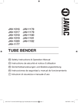
Identification—Major Components
881 and 881CT Hydraulic Benders
Saddle
Follow Bar
Shoe
E
E
E
Yoke (B)
Yoke Pin (G)
Ram (A)
Spring Clip (H)
Roller Unit (D)
Hitch Pin Clips (E)
Cylinder Block Pin Unit (F)
Connecting Bar Unit (C)
Saddle Pin Unit (M)
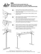
1813 Bending Table
Ram Positioner (33) Pipe Vise Unit (38) Leg Support Unit (23)
Leg (25)
Pump Table Support (26)
Bender Mounting Unit (27)
Pipe Clamp (34)

881 and 881CT Hydraulic Benders
Greenlee Tools, Inc. 4455 Boeing Dr. • Rockford, IL 61109-2988 USA • 815-397-7070
6
Assembly and Operation Instructions
881 and 881CT—Floor Operation (refer to “Identification—Major Components”)
1. Lay out the connecting bars (C), roller unit (D), and
two hitch pin clips (E).
Connecting Bar
with Bending
Instructions
Decals
2. Attach the roller unit to one of the connecting bars
with a hitch pin clip, as shown.
4. Position the ram and cylinder block so that, from the
operator’s point of view, the ram scale is up and to
the left of the ram.
3. Repeat Step 2 for the other connecting bar.
5. Attach the yoke (B) to the ram with the spring clip (H).
Decals face
outward
Ram
Travel
Scale

881 and 881CT Hydraulic Benders
Greenlee Tools, Inc. 4455 Boeing Dr. • Rockford, IL 61109-2988 USA • 815-397-7070
7
Assembly and Operation Instructions
881 and 881CT—Floor Operation (cont’d)
6. Select the shoe for the size of conduit to be bent.
Insert the shoe with the shoe size marking facing
up. Apply a light coat of high pressure grease to the
yoke pin then align either the EMT or Rigid/IMC hole
with the yoke and insert the yoke pin (G). Secure the
yoke pin with a hitch pin clip (E).
7. Remove one hitch pin clip from the roller shaft.
8. Lift the connecting bar and insert the follow bar.
Note: Insert the end marked START.
9. Reinsert the hitch pin clip into the roller shaft.

881 and 881CT Hydraulic Benders
Greenlee Tools, Inc. 4455 Boeing Dr. • Rockford, IL 61109-2988 USA • 815-397-7070
8
Assembly and Operation Instructions
881 and 881CT—Floor Operation (cont’d)
Bending Mark
Saddle Insert Saddle
10. Attach the hose (L) to the pump and ram.
11. Make sure the shoe and follow bar grooves are
clean. Insert the conduit into the bender.
12. Set the conduit into the groove of the shoe. Rotate
the shoe as necessary to align the saddle with the
shoe. Position the saddle so the saddle insert is
toward the operator, as shown. Attach the saddle to
the shoe with the saddle pin unit (M); secure the pin
unit with the hitch pin clip (E).
Note: Align the bending mark on the conduit with
the outside edge of the saddle insert.
13. Rotate the pump control lever counterclockwise.
Activate the hydraulic pump until the shoe just con-
tacts the conduit. Check that the saddle and follow
bar are snug. Be sure that the follow bar contacts
the saddle. Be sure that the bending mark on the
conduit is aligned with the front edge of the saddle
insert. Calibrate the bender (refer to “Calibrate
Bender Before Bending” under “Table 3—Ram
Travel”).
Activate the hydraulic pump to begin the bend.
14. 10° of bend.
Follow the instructions and safety information
supplied with your hydraulic pump.
The instructions provided here apply to Greenlee
960 (shown in the illustrations) and 980 (not shown)
hydraulic pumps only.

881 and 881CT Hydraulic Benders
Greenlee Tools, Inc. 4455 Boeing Dr. • Rockford, IL 61109-2988 USA • 815-397-7070
9
Assembly and Operation Instructions
881 and 881CT—Floor Operation (cont’d)
15. 45° of bend.
17. 90° of bend.
16. 60° of bend.
18. Release the hydraulic pressure. The ram will retract.
20. The 90° bend is complete.
19. Remove the saddle pin.

881 and 881CT Hydraulic Benders
Greenlee Tools, Inc. 4455 Boeing Dr. • Rockford, IL 61109-2988 USA • 815-397-7070
10
Assembly and Operation Instructions
881 and 881CT with 1813 Bending Table (refer to “Identification—Major Components”)
1. Lay out the connecting bars (C), roller unit (D), and
two hitch pin clips (E).
Connecting Bar
with Bending
Instructions
Decals
2. Attach the roller unit to one of the connecting bars
with a hitch pin clip, as shown.
4. Insert 29" leg (25) into leg support unit (23). Tighten
the cap screw (24). Repeat for the other three legs.
5. Insert two 10-foot lengths of IMC or rigid conduit
into
the leg support unit (23). Tighten four cap screws
(24).
Note: These lengths of conduit are not furnished
with the 1813 Bending Table.
3. Repeat Step 2 for the other connecting bar.
6. Position the bender mounting unit (27) as shown,
and slide it, tabs rst, onto the two 10-foot conduits.
Decals face
outward
Tabs

881 and 881CT Hydraulic Benders
Greenlee Tools, Inc. 4455 Boeing Dr. • Rockford, IL 61109-2988 USA • 815-397-7070
11
Assembly and Operation Instructions
881 and 881CT with 1813 Bending Table (cont’d)
15"
7. Position the bender mounting unit 15" from the
leg support unit. Tighten the two bender mounting
unit screws (28).
8. Slide the pipe vise unit (38) onto the two 10-foot
conduits, as shown.
9. Attach the second leg support unit (23) to the
10-foot conduits. Tighten the four screws (24).
10. Hang the two pipe clamps (34) over each of the
10-foot conduits. Set the pipe clamps 5" and 12"
from the bender mounting unit. Mount the pump
supports (26) onto the clamps. Do not tighten
the clamps.
Pipe Clamp
5"
Pump Support Unit
12"

881 and 881CT Hydraulic Benders
Greenlee Tools, Inc. 4455 Boeing Dr. • Rockford, IL 61109-2988 USA • 815-397-7070
12
Assembly and Operation Instructions
881 and 881CT with 1813 Bending Table (cont’d)
Pump
Reservoir
Pump
Bracket
11 and 12. Level the table at both ends.
13. Remove the rubber feet/casters from the pump.
Attach the pump bracket (64) to the pump with the
pump bracket mounting hardware (40–43). See
illustration.
14. Slide the pump onto the pump supports. Tighten
the screws on the lower sides of the pump brackets
to secure the pump. Verify that the pump supports
are 5" and 12" from the bender mounting unit.
Tighten the pipe clamp screws.
15 and 16. Load the connecting bar and roller unit into
the bender mounting unit.

881 and 881CT Hydraulic Benders
Greenlee Tools, Inc. 4455 Boeing Dr. • Rockford, IL 61109-2988 USA • 815-397-7070
13
Assembly and Operation Instructions
881 and 881CT with 1813 Bending Table (cont’d)
START
17. Insert the follow bar into the bender with the end
marked START, as shown.
18. Support the rear of the follow bar on the pipe
vise unit.
21. Attach the hydraulic tting unit (29) to the ram, and
connect the hose to the tting unit. Set the cylinder
and yoke unit on the follow bar. Rotate the pump
control lever counterclockwise.
19 and 20. Insert the ram positioner (33).

881 and 881CT Hydraulic Benders
Greenlee Tools, Inc. 4455 Boeing Dr. • Rockford, IL 61109-2988 USA • 815-397-7070
14
Assembly and Operation Instructions
881 and 881CT with 1813 Bending Table (cont’d)
22. Activate the hydraulic pump to extend the ram
approximately 14". DO NOT OVER EXTEND. Attach
the yoke to the ram positioner with the yoke pin (G).
Secure the yoke pin with a hitch pin clip (E).
23. Insert one cylinder block pin (F) into the hole marked
3" CONDUIT as shown.
24 and 25. Swing the ram unit into position.

881 and 881CT Hydraulic Benders
Greenlee Tools, Inc. 4455 Boeing Dr. • Rockford, IL 61109-2988 USA • 815-397-7070
15
Assembly and Operation Instructions
881 and 881CT with 1813 Bending Table (cont’d)
Saddle Pin
26. Remove the cylinder block pin from the 3" conduit
hole in the connecting bar. Rotate the pump control
lever clockwise to retract the ram. Position the
cylinder block at the proper location for the size of
conduit to be bent. Insert the two cylinder block
pins (F) through the connecting bars and through
the cylinder block. Secure the pins with two hitch
pin clips (E).
27. Remove the yoke pin from the ram positioner.
29. Load the shoe into the bender with the saddle pin
hole to the left, as shown.
28. Remove the ram positioner from the connecting
bar unit.

881 and 881CT Hydraulic Benders
Greenlee Tools, Inc. 4455 Boeing Dr. • Rockford, IL 61109-2988 USA • 815-397-7070
16
Assembly and Operation Instructions
881 and 881CT with 1813 Bending Table (cont’d)
30. Rotate the pump control lever counterclockwise.
Activate the hydraulic pump to advance the shoe
until the yoke is aligned with the proper shoe yoke
pin hole (EMT or IMC/Rigid).
31. Apply a light coat of high pressure grease to
lubricate the yoke pin, then attach the yoke to the
shoe with the yoke pin (G). Secure the yoke pin with
a hitch pin clip (E).
32. Rotate the pump control lever clockwise to retract
the ram.
33. Remove the vise unit from its position below the
follow bar. Slide the vise unit to the far end of the
bending table.
34. Insert the conduit to be bent. Rotate the pump
control
lever counterclockwise and advance the
shoe until it nearly contacts the conduit.

881 and 881CT Hydraulic Benders
Greenlee Tools, Inc. 4455 Boeing Dr. • Rockford, IL 61109-2988 USA • 815-397-7070
17
Assembly and Operation Instructions
881 and 881CT with 1813 Bending Table (cont’d)
Saddle
Pin
Saddle Insert Saddle
Align bending mark with
front edge of saddle insert.
35. Position the vise unit at a distance from the pump
support so that the vise unit will not contact the
pump support before the bend is complete. Clamp
the conduit down in the vise unit.
36. Push the follow bar back (to the right in the illustra-
tion) until the follow bar foot contacts the bender
mounting unit. Position the saddle and saddle pin
(M) where they can be reached for assembly.
37. Rock the bender frame as shown and rotate the
shoe back for the assembly of the saddle and pin.
38. Hold the shoe against the conduit and position the
saddle so the saddle insert is toward the operator.
Align the hole in the saddle with the hole in the shoe
and insert the saddle pin (M). Secure the saddle pin
with the hitch pin clip (E).
39. Allow the bender to rock forward and ensure that
the follow bar comes forward with it, so that the
follow bar contacts the saddle.
40. Rotate the pump control lever counterclockwise.
Activate the hydraulic pump until the shoe just con-
tacts the conduit. Check that the saddle and follow
bar are snug, and that the follow bar is against the
saddle, as shown. Be sure that the bending mark
on the conduit is aligned with the front edge of
the saddle insert. Attach the model 1805 Bending
Degree Indicator (35) to the conduit. Zero the indica-
tor by rotating the degree wheel.
Follow the instructions and safety information
supplied with your hydraulic pump.

881 and 881CT Hydraulic Benders
Greenlee Tools, Inc. 4455 Boeing Dr. • Rockford, IL 61109-2988 USA • 815-397-7070
18
Assembly and Operation Instructions
881 and 881CT with 1813 Bending Table (cont’d)
41. Activate the hydraulic pump to begin the bend.
43. 30° of bend.
42. 15° of bend.
44. 45° of bend.
46. 75° of bend.
45. 60° of bend.

881 and 881CT Hydraulic Benders
Greenlee Tools, Inc. 4455 Boeing Dr. • Rockford, IL 61109-2988 USA • 815-397-7070
19
Assembly and Operation Instructions
881 and 881CT with 1813 Bending Table (cont’d)
47. 90° of bend.
49. Rotate the pump control lever clockwise to retract
the shoe.
48. Remove the 1805 Bending Degree Indicator.
50. Push the follow bar back to the start position.
52. Release the vise chain.
51. Remove the saddle pin and saddle.

881 and 881CT Hydraulic Benders
Greenlee Tools, Inc. 4455 Boeing Dr. • Rockford, IL 61109-2988 USA • 815-397-7070
20
Assembly and Operation Instructions
881 and 881CT with 1813 Bending Table (cont’d)
53. Remove the conduit from the bender.
54 and 55. The 90° bend is complete.
56. To change the follow bar, twist and remove.
La page est en cours de chargement...
La page est en cours de chargement...
La page est en cours de chargement...
La page est en cours de chargement...
La page est en cours de chargement...
La page est en cours de chargement...
La page est en cours de chargement...
La page est en cours de chargement...
La page est en cours de chargement...
La page est en cours de chargement...
La page est en cours de chargement...
La page est en cours de chargement...
La page est en cours de chargement...
La page est en cours de chargement...
La page est en cours de chargement...
La page est en cours de chargement...
La page est en cours de chargement...
La page est en cours de chargement...
La page est en cours de chargement...
La page est en cours de chargement...
La page est en cours de chargement...
La page est en cours de chargement...
La page est en cours de chargement...
La page est en cours de chargement...
La page est en cours de chargement...
La page est en cours de chargement...
La page est en cours de chargement...
La page est en cours de chargement...
La page est en cours de chargement...
La page est en cours de chargement...
La page est en cours de chargement...
La page est en cours de chargement...
La page est en cours de chargement...
La page est en cours de chargement...
La page est en cours de chargement...
La page est en cours de chargement...
La page est en cours de chargement...
La page est en cours de chargement...
La page est en cours de chargement...
La page est en cours de chargement...
La page est en cours de chargement...
La page est en cours de chargement...
La page est en cours de chargement...
La page est en cours de chargement...
La page est en cours de chargement...
La page est en cours de chargement...
La page est en cours de chargement...
La page est en cours de chargement...
La page est en cours de chargement...
La page est en cours de chargement...
La page est en cours de chargement...
La page est en cours de chargement...
La page est en cours de chargement...
La page est en cours de chargement...
La page est en cours de chargement...
La page est en cours de chargement...
La page est en cours de chargement...
La page est en cours de chargement...
La page est en cours de chargement...
La page est en cours de chargement...
La page est en cours de chargement...
La page est en cours de chargement...
La page est en cours de chargement...
La page est en cours de chargement...
La page est en cours de chargement...
La page est en cours de chargement...
La page est en cours de chargement...
La page est en cours de chargement...
La page est en cours de chargement...
La page est en cours de chargement...
La page est en cours de chargement...
La page est en cours de chargement...
La page est en cours de chargement...
La page est en cours de chargement...
La page est en cours de chargement...
La page est en cours de chargement...
La page est en cours de chargement...
La page est en cours de chargement...
La page est en cours de chargement...
La page est en cours de chargement...
La page est en cours de chargement...
La page est en cours de chargement...
La page est en cours de chargement...
La page est en cours de chargement...
-
 1
1
-
2
-
3
-
4
-
5
-
6
-
7
-
8
-
9
-
10
-
11
-
12
-
13
-
14
-
15
-
16
-
17
-
18
-
19
-
20
-
21
-
22
-
23
-
24
-
25
-
26
-
27
-
28
-
29
-
30
-
31
-
32
-
33
-
34
-
35
-
36
-
37
-
38
-
39
-
40
-
41
-
42
-
43
-
44
-
45
-
46
-
47
-
48
-
49
-
50
-
51
-
52
-
53
-
54
-
55
-
56
-
57
-
58
-
59
-
60
-
61
-
62
-
63
-
64
-
65
-
66
-
67
-
68
-
69
-
70
-
71
-
72
-
73
-
74
-
75
-
76
-
77
-
78
-
79
-
80
-
81
-
82
-
83
-
84
-
85
-
86
-
87
-
88
-
89
-
90
-
91
-
92
-
93
-
94
-
95
-
96
-
97
-
98
-
99
-
100
-
101
-
102
-
103
-
104
- Taper
- Manuel utilisateur
- Ce manuel convient également à
dans d''autres langues
Documents connexes
-
Greenlee 881 & 881CT Cam Trak Hydraulic Bender Manuel utilisateur
-
-
-
-
-
-
-
-
-
Autres documents
-
Klein Tools 51609 Mode d'emploi
-
Southwire MXB2000 Manuel utilisateur
-
Milwaukee 48-22-4070 Guide de démarrage rapide
-
Gardner Bender 960H Manuel utilisateur
-
 JAVAC JAV-1016 Safety Instructions & Operation Manual
-
RIDGID 300 Series Plumbing Benders Instruction Sheet
-
 Malco Pan Style Mini-Brake Guide d'installation
-
-
Carlisle DRX Ram Outfit Le manuel du propriétaire

