INSTRUCTION MANUAL
Read and understand all of the instructions and
safety information in this manual before operating
or servicing this tool.
Register this product at www.greenlee.com
52060434 © 2011 Greenlee Textron Inc. 6/11
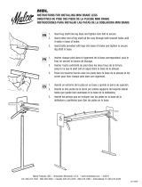
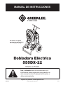
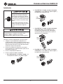
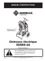
555DX-22
Electric Bender
Shown with optional
1-1/2" to 2" rigid
shoe group
Patents Pending
Español ............... 25
Français .............. 49

555DX-22 Electric Bender
Greenlee / A Textron Company 4455 Boeing Dr. • Rockford, IL 61109-2988 USA • 815-397-7070
2
All specications are nominal and may change as design
improvements occur. Greenlee Textron Inc. shall not be liable for
damages resulting from misapplication or misuse of its products.
555 is a registered trademark of Greenlee Textron Inc.
KEEP THIS MANUAL
Table of Contents
Description .................................................................... 2
Safety ............................................................................ 2
Purpose of this Manual ................................................. 2
Important Safety Information .....................................3–5
Grounding Instructions .................................................. 6
Specications ................................................................ 6
Identication .................................................................. 7
Setup ..........................................................................8–9
Operation ................................................................ 10–11
Illustrated Bending Glossary ....................................... 12
Bending Instructions ..............................................13–14
Additional Bending Instructions .............................15–17
Additional Bending Tables ......................................18–23
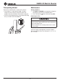
Transporting Bender .................................................... 24
Maintenance ................................................................ 24
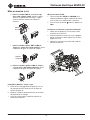
Description
The Greenlee 555DX-22 Electric Bender is intended to
bend 1/2" to 2" conduit and pipe. Bending shoe groups
are available to accommodate the following types of
conduit and pipe:
• Electrical Metallic Tubing
• Intermediate Metallic Conduit
• Rigid Conduit
• PVC-Coated Rigid Conduit
• Schedule 40 Pipe
• Aluminum Rigid
• Stainless Steel
In addition to the 555DX-22 bender, this manual also
applies to the 555DXR-22 bender, which includes
accessories for bending Rigid Conduit and Schedule 40
Pipe.
Safety
Safety is essential in the use and maintenance of
Greenlee tools and equipment. This instruction manual
and any markings on the tool provide information for
avoiding hazards and unsafe practices related to the
use of this tool. Observe all of the safety information
provided.
Purpose of this Manual
This manual is intended to familiarize all personnel with
the safe operation and maintenance procedures for the
Greenlee 555DX-22 Electric Bender.
Keep this manual available to all personnel.
Replacement manuals are available upon request at no
charge at www.greenlee.com.
Do not discard this product or throw away!
For recycling information, go to www.greenlee.com.

555DX-22 Electric Bender
Greenlee / A Textron Company 4455 Boeing Dr. • Rockford, IL 61109-2988 USA • 815-397-7070
3
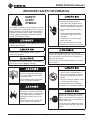
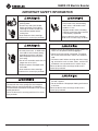
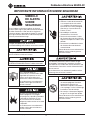
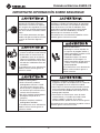
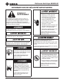
IMPORTANT SAFETY INFORMATION
SAFETY
ALERT
SYMBOL
This symbol is used to call your attention to hazards
or unsafe practices which could result in an injury or
property damage. The signal word, dened below,
indicates the severity of the hazard. The message
after the signal word provides information for pre-
venting or avoiding the hazard.
Immediate hazards which, if not avoided, WILL result
in severe injury or death.
Hazards which, if not avoided, COULD result in
severe injury or death.
Hazards or unsafe practices which, if not avoided,
MAY result in injury or property damage.
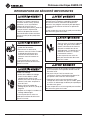
Read and understand all of the
instructions and safety information
in this manual before operating or
servicing this tool.
Failure to observe this warning will
result in severe injury or death.
Do not use this tool in a hazardous
environment. Hazards include am-
mable liquids, gases, or other materi-
als. Using this tool in a hazardous
environment can result in a re or
explosion.
Failure to observe this warning will
result in severe injury or death.
Electric shock hazard:
• Connect the power cord to a
220 volt, 15 amp receptacle on a
ground fault protected circuit only.
Refer to “Grounding Instructions.”
• Do not modify the power cord or
plug.
• Inspect the power cord before
use. Repair or replace the cord if
damaged.
• Disconnect the unit from power
before servicing.
Failure to observe these warnings
could result in severe injury or death.
For continued protection against risk of re and
electric shock, replace ONLY with same manufacturer,
type, and rating of fuse. Refer to the “Maintenance”
section of this manual.
Failure to observe this warning could result in severe
injury or death.
• Do not use in dangerous environ-
ment. Do not use power tools in
damp or wet locations, or expose
them to rain. Keep work area well
lighted.
• Do not immerse the pendant switch
in water or any other liquid.
Failure to observe these warnings
could result in severe injury or death.
Always use safety glasses. Everyday
glasses only have impact resistant
lenses; they are NOT safety glasses.
When using in dusty environment, use
face or dust mask.
Failure to wear eye protection could
result in serious eye injury from ying
debris.

555DX-22 Electric Bender
Greenlee / A Textron Company 4455 Boeing Dr. • Rockford, IL 61109-2988 USA • 815-397-7070
4
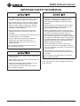
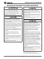
IMPORTANT SAFETY INFORMATION
• Keep guards in place and in
working order.
• Remove any tools from bender
before operating. Form habit of
checking to see that all tools are
removed from bender before
turning it on.
Failure to observe these warnings
could result in severe injury or death.
Extension cords:
• Use only three-wire, 12 AWG exten-
sion cords that have three-prong
grounding-type plugs and three-
hole receptacles that accept the
tool’s plug.
• Do not use extension cords that are
longer than 30 m (100').
• Repair or replace damaged exten-
sion cords.
Failure to observe these warnings
could result in severe injury or death.
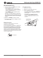
Make sure that the handle is properly installed and
secured with the safety spring clips and snap pins
before lifting or moving the bender. An improperly
installed handle could allow the bender to fall, injuring
nearby personnel.
Failure to observe this warning could result in severe
injury or death.
Pinch points:
• Keep hands away from bending
shoe, rollers, and conduit when
bender is in use.
• Support conduit when unloading.
Conduit can become loose and fall
if not properly supported.
Failure to observe these warnings
could result in severe injury or death.
• Reduce the risk of unintentional starting. Make sure
switch is in off position before plugging in.
• Never leave tool running unattended. Turn power
off. Do not leave tool until it comes to a complete
stop.
• Disconnect tools before servicing and when chang-
ing accessories such as shoes, rollers, and the like.
Accidental start-up could result in serious injury.
Failure to observe these warnings could result in
severe injury or death.
• Never stand on tool. Serious injury could occur if
the tool is tipped.
• Do not overreach. Keep proper footing and balance
at all times.
Failure to observe these warnings could result in
severe injury or death.

555DX-22 Electric Bender
Greenlee / A Textron Company 4455 Boeing Dr. • Rockford, IL 61109-2988 USA • 815-397-7070
5
IMPORTANT SAFETY INFORMATION
• Conduit moves rapidly as it is bent. The path of
the conduit must be clear of obstructions. Be sure
clearance is adequate before starting the bend.
• Wear proper apparel. Do not wear loose clothing,
gloves, neckties, rings, bracelets, or other jewelry
which may get caught in moving parts. Nonslip
footwear is recommended. Wear protective hair
covering to contain long hair.
• Do not force rollers or alter tool. It will do the
job better and safer at the rate for which it was
designed.
• Use right tool. Do not force tool or attachment to do
a job for which it was not designed.
• Use this tool for the manufacturer’s intended
purpose only. Use other than that which is
instructed in this manual can result in injury or
property damage.
Failure to observe these precautions may result in
injury or property damage.
• Keep work area clean. Cluttered areas and benches
invite accidents.
• Keep children away. All visitors should be kept safe
distance from work area.
• Make workshop kid proof with padlocks, master
switches, or by removing starter keys.
Failure to observe these precautions may result in
injury or property damage.
• Inspect the bender before use. Replace worn,
damaged, or missing parts with Greenlee replace-
ment parts. A damaged or improperly assem-
bled component could break and strike nearby
personnel.
• Maintain tools with care. Keep tool clean for best
and safest performance. Follow instructions for
lubricating and changing accessories.
• Check damaged parts. Before further use of the
tool, a guard or other part that is damaged should
be carefully checked to determine that it will
operate properly and perform its intended func-
tion. Check for alignment of moving parts, binding
of moving parts, breakage of parts, mounting, and
any other conditions that may affect its operation.
A guard or other part that is damaged should be
properly repaired or replaced.
• Use recommended accessories. Consult the
instruction manual for recommended accessories.
The use of improper accessories may cause risk of
injury to persons.
• Some bender parts and accessories are heavy
and may require more than one person to lift and
assemble.
Failure to observe these precautions may result in
injury or property damage.
Note: Keep all decals clean and legible, and replace
when necessary.

555DX-22 Electric Bender
Greenlee / A Textron Company 4455 Boeing Dr. • Rockford, IL 61109-2988 USA • 815-397-7070
6
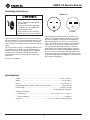
Grounding Instructions
Electric shock hazard:
• Do not modify the plug provided
with the tool.
• Connect this tool to a grounded
receptacle on a 15 amp ground
fault protected circuit.
Failure to observe these warnings
could result in severe injury or death.
This tool must be grounded. In the event of a malfunc-
tion or breakdown, an electrical ground provides a path
of least resistance for the electric current. This path of
least resistance is intended to reduce the risk of electric
shock.
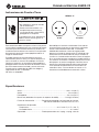
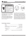
This tool’s electric cord has a grounding conductor and
a grounding plug as shown. Do not modify the plug.
Connect the plug to a corresponding GFCI-protected
receptacle that is properly installed and grounded
in accordance with all national and local codes and
ordinances.
Do not use an adapter.
NEMA 6-15
Plug Receptacle
Do not modify the plug provided. If it will not t the
outlet, have the proper outlet installed by a qualied
electrician. Improper connection of the equipment-
grounding conductor can result in a risk of electric
shock. The conductor with insulation having an outer
surface that is green with or without yellow stripes
is the equipment-grounding conductor. If repair or
replacement of the electric cord or plug is necessary,
do not connect the equipment-grounding conductor
to a live terminal. Check with a qualied electrician or
service personnel if the grounding instructions are not
completely understood, or if in doubt as to whether the
tool is properly grounded.
Specifications
Height ..................................................................................................100.1 cm (39.4")
Width ........................................................................................................68 cm (26.8")
Depth .....................................................................................................58.4 cm (23.0")
Mass/Weight (bender without shoes or roller supports ..........................124 kg (273 lb)
Power Supply .................................................................................... 220 VAC, 15 amp
GFCI-protected receptacle
Operating Conditions
Temperature .......................................................... –20 °C to 49 °C (–5 °F to 120 °F)
Relative Humidity ....................................................................................0% to 98%
Capacity .............................................................. 1/2" to 2" conduit, schedule 40 pipe

555DX-22 Electric Bender
Greenlee / A Textron Company 4455 Boeing Dr. • Rockford, IL 61109-2988 USA • 815-397-7070
7
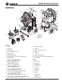
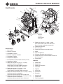
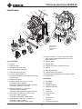
Identification
Features
1. Handle
2. Lifting bar
3. Shoe retainer
4. Roller engagement arm
5. Roller retainer
6. Pendant receptacle
7. Main power (On-Off) switch/circuit breaker
8. Roller adapter
9. 1/2" to 1-1/4" support roller
13854 for combination shoes
00936 for rigid only shoe
17986 for EMT only shoe
10. 1-1/2" to 2" support roller
13853 for combination shoes
17984 for rigid only shoe
11. 1-1/2" to 2" EMT squeeze rollers
13857 for combination shoes
13851 for EMT, single-groove type shoes
12. 1-1/2" to 2" IMC squeeze rollers
13856 for combination shoes
13852 for IMC, single-groove type shoes
13. 1-1/2" and 2" tail rollers for EMT and IMC single-
groove shoes (use with squeeze rollers)
H
I
20
F
G
K
7
21
5
A
B
6
2
D
E
11
9
10
3
14
C
4
12
8
17
16
19
18
15
J
1
13
Identification
14. Absolute encoder
15. Kick bar
16. Power cord with tie strap
17. Motor
18. Gearbox
19. Motor debris guard
20. Instruction manual storage compartment
21. Fuse holder
Decals
A. EMT roller
B. IMC roller
C. Engage rollers
D. Protractor
E. Bending
F. Instruction
G. Warning
H. Lifting
I. Identication
J. Squeeze
K. Bending tables
Squeeze rollers
illustrated in
raised/engaged
position.

555DX-22 Electric Bender
Greenlee / A Textron Company 4455 Boeing Dr. • Rockford, IL 61109-2988 USA • 815-397-7070
8
Setup
Always use safety glasses. Everyday
glasses only have impact resistant
lenses; they are NOT safety glasses.
When using in dusty environment, use
face or dust mask.
Failure to wear eye protection could
result in serious eye injury from ying
debris.
Disconnect tools before servicing and when chang-
ing accessories such as shoes, rollers, and the like.
Accidental start-up could result in serious injury.
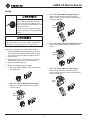
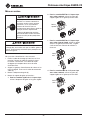
Refer to the “Identication” section of this manual.
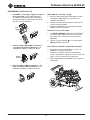
1. Slide the appropriate bending shoe onto the main
spindle. Orient the shoe so that the hook is about
90° clockwise from the sprocket spoke with two
drive lug holes.
2. Align the drive studs in the shoe with the holes in
the sprocket. Secure with the shoe retainer (3).
3. Mount the roller adapter (8).
4. Mount the appropriate roller support:
a. For 1-1/2" and 2" rigid, use the roller adapter
and rigid rollers.
10
8
b. For 1-1/2" and 2" EMT with combination
shoe, use the rigid support rollers and EMT
squeeze rollers.
10
8
11
Silver
Color
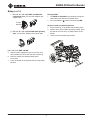
c. For 1-1/2" and 2" EMT with single-groove
shoe, use the tail rollers and EMT squeeze
rollers. Keep the squeeze roller size to be used
toward the bender.
13
8
11
Black
Color
d. For 1-1/2" and 2" IMC with combination shoe,
use the rigid support rollers and IMC squeeze
rollers.
10
8
12
Green
Color
e. For 1-1/2" and 2" IMC with single-groove
shoe, use the tail rollers and IMC squeeze
rollers. Keep the squeeze roller size to be used
toward the bender.
13
8
12
Black
Color

555DX-22 Electric Bender
Greenlee / A Textron Company 4455 Boeing Dr. • Rockford, IL 61109-2988 USA • 815-397-7070
9
Setup (cont’d)
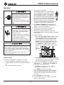
f. For 1/2" to 1-1/4" rigid, EMT, and IMC with
combination shoe, use the roller adapter and
support roller.
9
8
Triangle
Opening
g. For 1/2" to 1-1/4" rigid and IMC with rigid only
shoe, use the roller adapter and support roller.
9
8
For 1-1/2" to 2" EMT and IMC
5. Slide the roller engagement arm (4) over the main
roller spindle and secure with the roller retainer (5).
6. Mark the conduit according to bend layout
instructions.
7. Place the bender in the desired vertical or horizontal
position.
Zeroing 555DX
1. Use BEND or UNLOAD on the pendant to align the
shoe pointer with zero on the bender decal.
2. Press and hold the
button while pressing JOG.
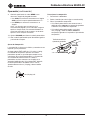
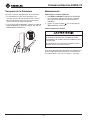
To place bender in horizontal position
1. Ensure handle (1) is on bender and pinned in place.
2. Stand in back of the bender, grasp the handle, place
one foot on the kick bar (14), and pull back on the
handle.
3. Gently lower the bender into position.

555DX-22 Electric Bender
Greenlee / A Textron Company 4455 Boeing Dr. • Rockford, IL 61109-2988 USA • 815-397-7070
10
Operation
Always use safety glasses. Everyday
glasses only have impact resistant
lenses; they are NOT safety glasses.
When using in dusty environment, use
face or dust mask.
Failure to wear eye protection could
result in serious eye injury from ying
debris.
Pinch points:
• Keep hands away from bending
shoe, rollers, and conduit when
bender is in use.
• Support conduit when unloading.
Conduit can become loose and fall
if not properly supported.
Failure to observe these warnings
could result in severe injury or death.
Wear proper apparel. Do not wear loose clothing,
gloves, neckties, rings, bracelets, or other jewelry
which may get caught in moving parts. Nonslip foot-
wear is recommended. Wear protective hair covering
to contain long hair.
Failure to observe this precaution could result in
severe injury or death.
Bending Conduit
Refer to the “Identication” section of this manual.
1. Plug the bender into a grounded 15 amp outlet.
2. Plug the pendant switch into the pendant receptacle
(6).
3. Turn on the main power switch (7).
4. Verify the shoe orientation.
If the pendant display shows approximately
the same degree as the pointer on the shoe,
the shoe position is correct. If not, rotate the
shoe’s engagement points in the sprocket
90° by hand or zero the pendant display. The
shoe units in the 12580 and 12581 bending
groups have drive studs that will align in only
one position with the holes in the sprocket.
Re-zero the pendant display to align the desired
shoe pointer with zero on the bender decal.
5. Press BEND or UNLOAD on the pendant until
the shoe is 5° to 10° before the starting point (0°)
(approx. –5° on 555DX pendant).
6. Load the conduit so that the bending mark is
aligned with the front edge of the hook.
7. Determine the angle to stop at to achieve the
desired bend angle from the bending decal or tables
in this manual.
8. Bend the conduit.
a. For 1-1/2" and 2" EMT or IMC conduit, use the
roller engagement arm (4) to raise the squeeze
rollers and position them so that both rollers
make contact with the conduit. Note that the
engagement arm can be placed in either of two
positions to facilitate hand or foot actuation.
Press BEND while applying pressure to the
engagement arm until the rollers hit their stop.
Roller
Engagement
Arm
b. For all other conduit, press BEND while making
sure the bend mark stays at the front of the hook
until the conduit contacts the tail roller.
9. Continue to press BEND until reaching the desired
bend angle.9. Continue to press BEND until
reaching the desired bend angle.
• Use JOG to sneak up on an angle. JOG will
advance the shoe about 1/2°.
• Use BEND to sneak up on an angle.
Note: The angles displayed on the bending decal
and the pendant may not always be in sync due
to shoe casting variations, although they will be
consistent.
10. Press UNLOAD to free the conduit.
11. Twist the conduit to release it from the hook and
remove it from the shoe.

555DX-22 Electric Bender
Greenlee / A Textron Company 4455 Boeing Dr. • Rockford, IL 61109-2988 USA • 815-397-7070
11
Operation (cont’d)
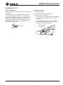
Squeeze Adjustment
Squeeze is factory set and should not normally need to
be adjusted.
When bending 1-1/2" or 2" EMT or IMC, the amount
of squeeze applied to the conduit can be adjusted to
compensate for conduit variations. The squeeze is set
properly if the conduit does not contact the roller on
the tail roller support (10) while bending EMT. Also, the
conduit should not be more than approximately 1/4"
(6mm) above the tail roller.
1/4" (6 mm) max.
To adjust the squeeze:
1. Unplug the bender.
2. Remove screw (refer to gure below).
3. Rotate the squeeze adjuster:
• If the conduit is contacting the tail roller, increase
the squeeze by rotating the squeeze adjuster
clockwise.
• If the conduit is more than 1/4" (6 mm) above
the roller, decrease the squeeze by rotating the
squeeze adjuster counterclockwise.
INCREASE
DECREASE
Squeeze Adjuster
Holding Screw

555DX-22 Electric Bender
Greenlee / A Textron Company 4455 Boeing Dr. • Rockford, IL 61109-2988 USA • 815-397-7070
12
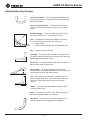
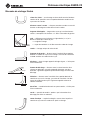
Illustrated Bending Glossary
back-to-back bend — any U-shaped bend formed by two
parallel 90° bends with a straight section of conduit or pipe
between the bends.
center-to-center distance — the distance between the
successive bends that make up an offset or a three-bend
saddle.
developed length — the actual length of pipe that will be
bent; refer to distance “d” in the illustration at left.
gain — the difference between the straight-line distance
(a + a) and the shorter radial distance, (d) where:
q = angle of bend
r = the centerline bending radius of the bending shoe
kick — single bend of less than 90°
leg length — the distance from the end of a straight section
of conduit or pipe to the bend; measured from the end to the
outside edge of the conduit or pipe.
offset bend — two opposite bends with the same degree of
bend; used to avoid an obstruction.
offset height — the distance between the two legs of
an offset bend, measured perpendicular to the two legs; also
called amount of offset and depth of offset.
rise — the distance from the end of a straight section of
conduit or pipe to the bend; measured from the end to the
center line of the conduit or pipe. Also called stub or
stub-up.
saddle — a three-bend or four-bend combination; used
to avoid an obstruction.
shrink — the amount of conduit “lost” when laying out an
offset bend working toward an obstruction.
springback — the amount, measured in degrees, that a
conduit or pipe tends to straighten after being bent.
a
a
d
r
Offset Height

555DX-22 Electric Bender
Greenlee / A Textron Company 4455 Boeing Dr. • Rockford, IL 61109-2988 USA • 815-397-7070
13
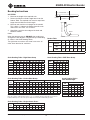
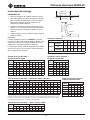
Bending Instructions
90° STUBS
1. Measure the length of the required stub.
2. Refer to the Minimum Stub Length formula on the
Deduct Table. The required stub must be equal to or
longer than the Minimum Stub Length.
3. Measure and mark the stub length on the conduit.
This is Mark 1. Subtract the Deduct from this mark
and make a new mark. This is Mark 2.
4. Align Mark 2 with the front edge of the hook and
bend the conduit.
Notes:
When the operator presses UNLOAD, the conduit may
spring back a few degrees. Compensate by overbending
as shown in the Scale Reading Tables.
The rigid shoe can make a 180° bend in one shot. All
other shoes bend to 90° maximum.
Deduct Table
CONDUIT SIZE 1/2 3/4 1 1-1/4 1-1/2 2
DEDUCT
COMBO SHOE
RIGID/IMC
7-1/2 9 11 13-5/8 14-7/8 16-1/8
COMBO SHOE
EMT
7-1/2 9 11 13-5/8 14-7/8 16-3/8
RIGID ONLY
SHOE
7-1/2 9 11 14 14-1/4 16-1/8
MINIMUM STUB LENGTH = DEDUCT PLUS 2 INCHES
Figures are approximate
Scale Reading Table—Combo Shoe Group
CONDUIT
SIZE
RIGID EMT IMC
15° 30° 45° 60° 90° 15° 30° 45° 60° 90° 15° 30° 45° 60° 90°
1/2 17 33 49 64 96 16 32 48 63 95 20 36 51 67 98
3/4 17 33 48 64 95 17 33 48 64 95 19 35 50 66 97
1 17 32 48 63 94 17 33 48 64 95 19 35 50 66 97
1-1/4 17 33 48 64 95 17 33 49 64 96 19 35 50 66 97
1-1/2 17 32 48 63 94 16 31 47 62 93 17 33 49 64 96
2 17 32 48 63 94 16 31 47 62 93 19 34 50 65 96
Figures are approximate
Note: Due to varying conduit material properties, 1-1/2" or 2" aluminum rigid may require IMC squeeze rollers for
bending. If flattening occurs, reduce the squeeze setting two positions and use IMC bending procedures.
Scale Reading Table—Rigid Shoe Group
CONDUIT
SIZE
RIGID IMC
15° 30° 45° 60° 90° 15° 30° 45° 60° 90°
1/2 18 35 50 66 96 20 36 51 67 98
3/4 17 32 47 63 95 20 36 51 67 97
1 17 33 48 65 95 21 36 51 66 97
1-1/4 18 33 48 63 95 18 33 50 65 96
1-1/2 19 34 49 65 95
2 18 34 49 65 95
Figures are approximate
Scale Reading Table—EMT Shoe Group
CONDUIT
SIZE
EMT
15° 30° 45° 60° 90°
1/2 16 32 48 63 95
3/4 17 32 47 62 95
1 17 32 47 62 95
1-1/4 17 32 47 62 95
1-1/2 17 32 47 61 94
2 17 32 47 62 95
Figures are approximate
Scale Reading Table—
PVC-Coated Rigid
CONDUIT
SIZE
PVC-COATED RIGID
15° 30° 45° 60° 90°
1/2 16 31 47 62 93
3/4 15 31 46 62 93
1 16 32 47 63 94
1-1/4 16 31 47 62 93
1-1/2 18 33 49 64 95
2 19 34 50 65 96
Figures are approximate
Scale Reading Table—Single-Groove Shoes
CONDUIT
SIZE
EMT IMC
15° 30° 45° 60° 90° 15° 30° 45° 60° 90°
1/2 17 32 47 61 94 19 34 49 65 95
2 17 32 47 62 95 20 35 50 66 96
Figures are approximate
STUB LENGTH
DEDUCT
MARK 2
MARK 2
MARK 1
MARK 1
STUB LENGTH

555DX-22 Electric Bender
Greenlee / A Textron Company 4455 Boeing Dr. • Rockford, IL 61109-2988 USA • 815-397-7070
14
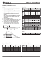
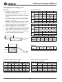
Offsets
1. Measure the height and length of the obstruction.
Select the angle to be used.
2. Refer to the Offset Table. The height of the obstruc-
tion must be equal to or greater than the minimum
offset.
3. Refer to the X Table to nd the X dimension. Refer
to the Offset Table to nd the center-to-center
distance.
Note: If the center-to-center distance is not shown,
calculate it by using the multipliers shown in the
Offset Table.
4. Mark the conduit as shown.
5. Insert the conduit into the bender. Align Mark 1 with
the front edge of the hook and bend the conduit.
6. Align Mark 2 with the front edge of the hook.
Without removing the conduit from the bender,
rotate the conduit 180°. Make the second bend.
LENGTH
HEIGHT
LENGTH
MARK 1 MARK 2
CENTER TO CENTER
DISTANCE
X
OBSTRUCTION
Offset Table
OFFSET }
2 4 6 8 10
15°
Max. Conduit
Size
3/4 1-1/2 2
Center-to-Center 7-3/4 15-7/16 23-3/16 30-15/16 38-5/8
30°
Max. Conduit
Size
3/4 1 1-1/2 2
Center-to-Center 8 12 16 20
45°
Max. Conduit
Size
1/2 1 1-1/4
Center-to-Center 8-1/2 11-5/16 14-1/8
OFFSET }
12 14 16 18 20 22
15°
Max. Conduit
Size
2
Center-to-Center 46-3/8 54-1/16 61-13/16 69-9/16 77-1/4 85
30°
Max. Conduit
Size
2
Center-to-Center 24 28 32 36 40 44
45°
Max. Conduit
Size
1-1/2 2
Center-to-Center 16-15/16 19-13/16 22-5/8 25-7/16 28-1/4 31-1/8
CENTER-TO-CENTER DISTANCE = OFFSET HEIGHT x MULTIPLIER
OFFSET
ANGLE
10° 15° 22-1/2° 30° 45°
MULTIPLIER 5.8 3.9 2.6 2.0 1.4
Figures are approximate
X Table
CONDUIT SIZE 1/2 3/4 1 1-1/4 1-1/2 2
“X” 3-1/16 3-1/16 3-3/16 4 4-1/4 4-1/2
Figures are approximate
Bending Instructions (cont’d)
Centerline Bending Radii—
Rigid and EMT Shoe Groups
SHOE
SIZE
EMT RIGID IMC
in mm in mm in mm
1/2 4-1/4 108 4-1/4 108 4-1/4 108
3/4 5-3/8 136.5 5-7/16 138 5-7/16 138
1 6-3/4 171.5 6-5/16 160 6-5/16 160
1-1/4 8-3/4 222 8-3/4 222 8-3/4 222
1-1/2 8-9/32 210 8-1/4 209 8-9/32 210
2 9-3/16 233 9-1/2 241 9-3/16 233
Centerline Bending Radii—
Combo Shoe Group
SHOE SIZE
EMT IMC/RIGID
in mm in mm
1/2 4-5/16 109.5 4-1/4 108
3/4 5-1/2 139.7 5-7/16 138.1
1 7 177.8 6-15/16 176.2
1-1/4 8-13/16 223.8 8-3/4 222.3
1-1/2 8-3/8 212.7 8-1/4 209.6
2 9-1/4 235.0 9 228.6

555DX-22 Electric Bender
Greenlee / A Textron Company 4455 Boeing Dr. • Rockford, IL 61109-2988 USA • 815-397-7070
15
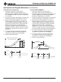
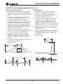
The following drawings and bending tables are intended
to provide the information necessary to accomplish
the most common types of bends. The bending tables
contain conduit marking information.
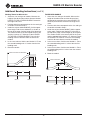
STUBS
1. Select the size and type of conduit. Determine the
height of stub and the angle to be used.
2. Find the table that corresponds to the size and type
of conduit selected in Step 1.
3. Under the column labeled ANGLE, nd the appro-
priate angle.
4. Find the row labeled Y. In the row at the top of the
page, nd the height (H) of the stub. The number
shown at the intersection of row Y and column H
is the distance Y. Place the bending mark Y inches
from the end of the conduit.
5. Bend the conduit.
Y
HEIGHT
MARK
ANGLE
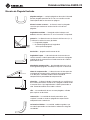
Additional Bending Instructions
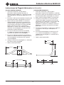
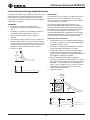
OFFSETS
An offset is used to route the conduit around an
obstruction. To make an offset, two equal bends are
required. The distance between the two bends is the
center-to-center distance.
When working past an obstruction, it is necessary to
determine the location of the rst bend. The center-to-
center distance is then used to determine the location of
the second bend. When working toward an obstruction,
it is necessary to determine the location of the second
bend. The center-to-center distance is then used to
determine the location of the rst bend.
Working Past an Obstruction
1. Select the size and type of conduit. Measure the
height of the obstruction and the distance labeled
LENGTH. Determine the angle to be used.
2. Find the table that corresponds to the size and type
of conduit selected in Step 1.
3. To the right of the size and type of conduit, nd the
dimension labeled X. Subtract X from LENGTH.
Place the rst bending mark this distance from the
end of the conduit.
4. Under the column labeled ANGLE, nd the appro-
priate angle. Find the row labeled L1. In the row at
the top of the page, nd the height (H) of the offset.
The number shown at the intersection of row L1 and
column H is L1. Place the second bending mark L1
inches from the rst bending mark.
5. Bend the conduit.
L1LENGTH – X
LENGTH
HEIGHT
START OF
FIRST
BEND
MARK 1 MARK 2
ANGLE
OBSTRUCTION

555DX-22 Electric Bender
Greenlee / A Textron Company 4455 Boeing Dr. • Rockford, IL 61109-2988 USA • 815-397-7070
16
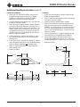
Additional Bending Instructions (cont’d)
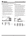
Working Toward an Obstruction
1. Select the size and type of conduit. Measure the
height of the obstruction and the distance labeled
LENGTH TO END OF SECOND BEND. Determine
the angle to be used.
2. Find the table that corresponds to the size and type
of conduit selected in Step 1.
3. Under the column labeled ANGLE, nd the appro-
priate angle. Find the row labeled Z. In the row at
the top of the page, nd the height (H) of the offset.
The number shown at the intersection of the Z row
and the H column is Z. Subtract Z from LENGTH
TO THE END OF SECOND BEND. Place the rst
bending mark this distance from the end of the
conduit.
4. In the same column, nd the row labeled L1. Place
the second bending mark L1 inches from the rst
bending mark.
5. Bend the conduit.
L1LENGTH – Z
LENGTH TO END OF SECOND BEND
HEIGHT
MARK 1 MARK 2
ANGLE
THREE-BEND SADDLE
1. Select the size and type of conduit. Measure the
height of the obstruction and the distance from
the end of the conduit to the center (LENGTH TO
CENTER) of the bend. Determine the angle to be
used.
2. Find the table that corresponds to the size and type
of conduit selected in Step 1.
3. Under the column labeled ANGLE, nd the appro-
priate angle. Find the row labeled Z. In the row at
the top of the page, nd the height (H) of the offset.
The number shown at the intersection of the Z row
and the appropriate H column is Z. Subtract Z from
the LENGTH TO CENTER. Place the rst bending
mark this distance from the end of the conduit.
4. In the same column, nd the row labeled L1. Place
the second bending mark L1 inches from the rst
bending mark.
5. In the same column, nd the row labeled L2. Place
the third bending mark L2 inches from the second
bending mark.
6. Bend the conduit.
L1LENGTH – Z
LENGTH TO CENTER
MARK 1
MARK 2
MARK 3
L2
ANGLE
HEIGHT

555DX-22 Electric Bender
Greenlee / A Textron Company 4455 Boeing Dr. • Rockford, IL 61109-2988 USA • 815-397-7070
17
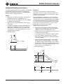
Additional Bending Instructions (cont’d)
FOUR-BEND SADDLE
1. Select the size and type of conduit. Measure the
height of the obstruction, the distance labeled
LENGTH, and the distance labeled STRAIGHT
SECTION. Determine the angle to be used.
2. Find the table that corresponds to the size and type
of conduit selected in Step 1.
3. Under the column labeled ANGLE, nd the appropri-
ate angle. Find the row labeled Z. In the row at the
top of the page, nd the height (H) of the offset. The
number shown at the intersection of the Z row and
the appropriate H column is Z. Subtract Z from the
LENGTH. Place the rst bending mark this distance
from the end of the conduit.
4. In the same column, nd the row labeled L1. Place
the second bending mark L1 inches from the rst
bending mark.
5. In the same column, nd the row labeled L2. Add L2
to the STRAIGHT SECTION. Place the third bending
mark this distance from the rst bending mark.
6. Make the nal bending mark L1 inches from the
third bending mark.
7. Bend the conduit.
LENGTH – Z
MARK 1 MARK 2 MARK 3
L2 + STRAIGHT SECTION
HEIGHT
STRAIGHT
SECTION
MARK 4
LENGTH
L1 L1
ANGLE
U-BENDS
1. Select the size and type of conduit. Determine the
LENGTH and the HEIGHT.
2. Find the table that corresponds to the size and type
of conduit selected in Step 1.
3. Under the column labeled ANGLE, nd 90°.
4. Find the row labeled Y. In the row at the top of the
page, nd the height (H) that corresponds to the
LENGTH. The number shown at the intersection of
the Y row and the appropriate H column is the dis-
tance Y. Place the bending mark Y inches from the
end of the conduit.
5. Find the row labeled L1, and go to the right to nd
the height (H) that corresponds to the HEIGHT.
6. The number shown at the intersection of the L1
row and the appropriate H column is L1. Place the
second bending mark L1 inches from the rst mark.
7. Bend the conduit.
Y
MARK 1
MARK 2
L1
LENGTH
HEIGHT

555DX-22 Electric Bender
Greenlee / A Textron Company 4455 Boeing Dr. • Rockford, IL 61109-2988 USA • 815-397-7070
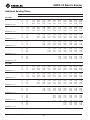
18
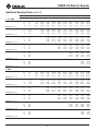
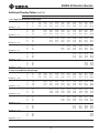
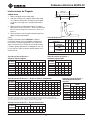
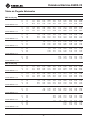
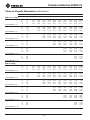
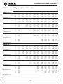
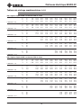
Additional Bending Tables
DIM ANGLE 2" 4" 6" 8" 10" 12" 15" 18" 24" 36"
1/2" EMT
Y 15 3.74 11.47 19.20 26.92 34.65 42.38 53.97 65.56 88.74 135.11
L1 15 7.72 15.45 23.18 30.90 38.63 46.36 57.95 69.54 92.72 139.09
L2 15 8.94 16.66 24.39 32.12 39.84 47.57 59.16 70.75 93.94 140.30
Z 15 10.70 18.16 25.62 33.09 40.55 48.02 59.21 70.41 92.80 137.59
MINIMUM H = 0.84
Y 22.5 1.37 6.60 11.82 17.05 22.28 27.50 35.34 43.18 58.86 90.22
L1 22.5 5.20 10.43 15.65 20.88 26.11 31.33 39.17 47.01 62.69 94.05
L2 22.5 7.02 12.25 17.48 22.70 27.93 33.16 41.00 48.83 64.51 95.87
Z 22.5 8.68 13.51 18.34 23.17 28.00 32.83 40.07 47.31 61.80 90.77
MINIMUM H = 1.48
Y 30 0.04 4.04 8.04 12.04 16.04 20.04 26.04 32.04 44.04 68.04
L1 30 7.94 11.94 15.94 19.94 23.94 29.94 35.94 47.94 71.94
L2 30 10.37 14.37 18.37 22.37 26.37 32.37 38.37 50.37 74.37
Z 30 11.42 14.89 18.35 21.82 25.28 30.48 35.67 46.07 66.85
MINIMUM H = 2.25
Y 45 1.23 4.05 6.88 9.71 12.54 16.78 21.02 29.51 46.48
L1 45 8.29 11.11 13.94 16.77 21.01 25.26 33.74 50.71
L2 45 11.93 14.76 17.59 20.42 24.66 28.90 37.39 54.36
Z 45 11.85 13.85 15.85 17.85 20.85 23.85 29.85 41.85
MINIMUM H = 4.14
Y 60 1.83 4.14 6.45 8.76 12.22 15.69 22.62 36.47
L1 60 8.74 11.05 13.36 16.82 20.29 27.21 41.07
L2 60 13.60 15.91 18.22 21.68 25.14 32.07 45.93
Z 60 11.99 13.14 14.30 16.03 17.76 21.22 28.15
MINIMUM H = 6.38
Y 90 1.00 3.00 5.00 8.00 11.00 17.00 29.00
L1 90 10.01 13.01 16.01 22.01 34.01
L2 90 17.30 20.30 23.30 29.30 41.30
Z 90 11.29 11.29 11.29 11.29 11.29
MINIMUM H = 11.29
3/4" EMT
Y 15 2.35 10.07 17.80 25.53 33.26 40.98 52.58 64.17 87.35 133.71
L1 15 7.72 15.45 23.17 30.90 38.63 46.36 57.95 69.54 92.72 139.08
L2 15 9.17 16.90 24.62 32.35 40.08 47.81 59.40 70.99 94.17 140.54
Z 15 11.79 19.26 26.72 34.19 41.65 49.11 60.31 71.51 93.90 138.68
MINIMUM H = 1.12
Y 22.5 0.05 5.28 10.50 15.73 20.95 26.18 34.02 41.86 57.54 88.90
L1 22.5 5.20 10.42 15.65 20.88 26.10 31.33 39.17 47.01 62.69 94.04
L2 22.5 7.37 12.60 17.83 23.05 28.28 33.50 41.34 49.18 64.86 96.22
Z 22.5 9.90 14.73 19.56 24.39 29.22 34.04 41.29 48.53 63.02 91.99
MINIMUM H = 1.94
Y 30 2.72 6.72 10.72 14.72 18.72 24.72 30.72 42.72 66.72
L1 30 7.93 11.93 15.93 19.93 23.93 29.93 35.93 47.93 71.93
L2 30 10.83 14.83 18.83 22.83 26.83 32.83 38.83 50.83 74.83
Z 30 12.77 16.23 19.70 23.16 26.62 31.82 37.02 47.41 68.19
MINIMUM H = 2.92
Y 45 2.67 5.50 8.33 11.15 15.40 19.64 28.12 45.09
L1 45 8.25 11.08 13.90 16.73 20.97 25.22 33.70 50.67
L2 45 12.60 15.43 18.25 21.08 25.33 29.57 38.05 55.02
Z 45 13.46 15.46 17.46 19.46 22.46 25.46 31.46 43.46
MINIMUM H = 5.27
Y 60 0.33 2.64 4.95 7.26 10.72 14.18 21.11 34.97
L1 60 10.95 13.26 16.72 20.19 27.12 40.97
L2 60 16.75 19.06 22.53 25.99 32.92 46.78
Z 60 15.04 16.20 17.93 19.66 23.12 30.05
MINIMUM H = 8.03
Y 90 1.13 3.13 6.13 9.13 15.13 27.13
L1 90 12.62 15.62 21.62 33.62
L2 90 21.32 24.32 30.32 42.32
Z 90 13.95 13.95 13.95 13.95
MINIMUM H = 13.95

555DX-22 Electric Bender
Greenlee / A Textron Company 4455 Boeing Dr. • Rockford, IL 61109-2988 USA • 815-397-7070
19
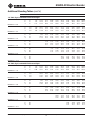
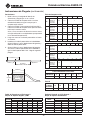
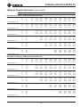
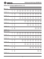
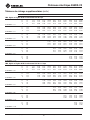
Additional Bending Tables (cont’d)
DIM ANGLE 2" 4" 6" 8" 10" 12" 15" 18" 24" 36"
1" EMT
Y 15 1.35 9.07 16.80 24.53 32.26 39.98 51.57 63.16 86.35 132.71
L1 15 7.72 15.44 23.17 30.90 38.63 46.35 57.95 69.54 92.72 139.08
L2 15 9.54 17.26 24.99 32.72 40.45 48.17 59.76 71.36 94.54 140.90
Z 15 12.51 19.98 27.44 34.91 42.37 49.83 61.03 72.23 94.62 139.40
MINIMUM H = 1.31
Y 22.5 4.33 9.56 14.78 20.01 25.24 33.07 40.91 56.59 87.95
L1 22.5 10.42 15.64 20.87 26.10 31.32 39.16 47.00 62.68 94.04
L2 22.5 13.15 18.37 23.60 28.82 34.05 41.89 49.73 65.41 96.77
Z 22.5 15.64 20.47 25.30 30.13 34.96 42.20 49.44 63.93 92.90
MINIMUM H = 2.29
Y 30 1.75 5.75 9.75 13.75 17.75 23.75 29.75 41.75 65.75
L 30 7.91 11.91 15.91 19.91 23.91 29.91 35.91 47.91 71.91
L2 30 11.55 15.55 19.55 23.55 27.55 33.55 39.55 51.55 75.55
Z 30 13.87 17.34 20.80 24.27 27.73 32.92 28.12 48.51 69.30
MINIMUM H = 3.47
Y 45 1.56 4.39 7.22 10.05 14.29 18.53 27.02 43.99
L1 45 11.01 13.84 16.67 20.91 25.16 33.64 50.61
L2 45 16.47 19.30 22.13 26.37 30.62 39.10 56.07
Z 45 16.98 18.98 20.98 23.98 26.98 32.98 44.98
MINIMUM H = 6.35
Y 60 1.33 3.64 5.95 9.42 12.88 19.81 33.67
L1 60 10.80 13.11 16.57 20.04 26.97 40.82
L2 60 18.08 20.39 23.85 27.32 34.24 48.10
Z 60 17.02 18.17 19.91 21.64 25.10 32.03
MINIMUM H = 9.74
Y 90 1.25 4.25 7.25 13.25 25.25
L1 90 15.02 21.02 33.02
L2 90 25.93 31.93 43.93
Z 90 17.12 17.12 17.12
MINIMUM H = 17.12
1-1/4" EMT
Y 15 0.26 7.99 15.72 23.45 31.17 38.90 50.49 62.08 85.27 131.63
L1 15 7.71 15.44 23.17 30.90 38.62 46.35 57.94 69.53 92.72 139.08
L2 15 10.07 17.80 25.52 33.25 40.98 48.71 60.30 71.89 95.07 141.44
Z 15 13.20 20.66 28.12 35.59 43.05 50.52 61.71 72.91 95.30 140.09
MINIMUM H = 1.48
Y 22.5 3.33 8.55 13.78 19.01 24.23 32.07 39.91 55.59 86.95
L1 22.5 10.41 15.63 20.86 26.09 31.31 39.15 46.99 62.67 94.03
L2 22.5 13.94 19.17 24.40 29.62 34.85 42.69 50.53 66.21 97.56
Z 22.5 16.60 21.43 26.26 31.09 35.91 43.16 50.40 64.89 93.86
MINIMUM H = 2.66
Y 30 0.72 4.72 8.72 12.72 16.72 22.72 28.72 40.72 64.72
L1 30 11.89 15.89 19.89 23.89 29.89 35.89 47.89 71.89
L2 30 16.61 20.61 24.61 28.61 34.61 40.61 52.61 76.61
Z 30 18.58 22.04 25.51 28.97 34.17 39.37 49.76 70.54
MINIMUM H = 4.09
Y 45 0.33 3.15 5.98 8.81 13.05 17.30 25.78 42.75
L1 45 10.93 13.75 16.58 20.83 25.07 33.55 50.52
L2 45 18.00 20.83 23.66 27.90 32.14 40.63 57.60
Z 45 18.82 20.82 22.82 25.82 28.82 34.82 46.82
MINIMUM H = 7.65
Y 60 2.11 4.42 7.89 11.35 18.28 32.14
L1 60 12.89 16.35 19.82 26.74 40.60
L2 60 22.32 25.79 29.25 36.18 50.04
Z 60 20.69 22.42 24.16 27.62 34.55
MINIMUM H = 11.92
Y 90 1.88 4.88 10.88 22.88
L1 90 20.13 32.13
L2 90 34.29 46.29
Z 90 21.38 21.38
MINIMUM H = 21.38

555DX-22 Electric Bender
Greenlee / A Textron Company 4455 Boeing Dr. • Rockford, IL 61109-2988 USA • 815-397-7070
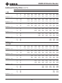
20
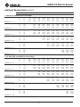
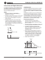
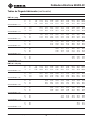
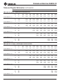
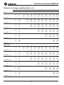
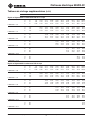
Additional Bending Tables (cont’d)
DIM ANGLE 2" 4" 6" 8" 10" 12" 15" 18" 24" 36"
1-1/2" EMT
Y 15 6.26 13.99 21.72 29.44 37.17 48.76 60.35 83.53 129.90
L1 15 7.71 15.44 23.17 30.90 38.62 46.35 57.94 69.53 92.72 139.08
L2 15 9.95 17.68 25.40 33.13 40.86 48.58 60.18 71.77 94.95 141.31
Z 15 14.42 21.88 29.35 36.81 44.28 51.74 62.94 74.13 96.53 141.31
MINIMUM H = 1.81
Y 22.5 1.77 7.00 12.22 17.45 22.68 30.52 38.36 54.03 85.39
L1 22.5 10.41 15.64 20.86 26.09 31.31 39.15 46.99 62.67 94.03
L2 22.5 13.76 18.98 24.21 29.44 34.66 42.50 50.34 66.02 97.38
Z 22.5 17.76 22.59 27.42 32.25 37.07 44.32 51.56 66.04 95.02
MINIMUM H = 3.11
Y 30 3.26 7.26 11.26 15.26 21.26 27.26 39.26 63.26
L1 30 11.90 15.90 19.90 23.90 29.90 35.90 47.90 71.90
L2 30 16.36 20.36 24.36 28.36 34.36 40.36 52.36 76.36
Z 30 19.67 23.14 26.60 30.07 35.26 40.46 50.85 71.64
MINIMUM H = 4.64
Y 45 1.84 4.67 7.50 11.74 15.98 24.47 41.44
L1 45 13.78 16.60 20.85 25.09 33.57 50.54
L2 45 20.47 23.30 27.55 31.79 40.27 57.24
Z 45 21.78 23.78 26.78 29.78 35.78 47.78
MINIMUM H = 8.33
Y 60 0.91 3.22 6.68 10.15 17.07 30.93
L1 60 16.40 19.87 26.80 40.65
L2 60 25.34 28.80 35.73 49.58
Z 60 23.22 24.95 28.42 35.34
MINIMUM H = 12.61
Y 90 0.89 3.89 9.89 21.89
L1 90 20.34 32.34
L2 90 33.74 45.74
Z 90 21.77 21.77
MINIMUM H = 21.77
2" EMT
Y 15 5.15 12.87 20.60 28.33 36.05 47.65 59.24 82.42 128.78
L1 15 7.71 15.44 23.17 30.90 38.62 46.35 57.94 69.53 92.71 139.08
L2 15 10.19 17.92 25.64 33.37 41.10 48.83 60.42 72.01 95.19 141.56
Z 15 14.77 22.24 29.70 37.17 44.63 52.10 63.29 74.49 96.88 141.66
MINIMUM H = 1.89
Y 22.5 0.88 6.11 11.33 16.56 21.79 29.62 37.46 53.14 84.50
L1 22.5 10.40 15.63 20.86 26.08 31.31 39.15 46.99 62.67 94.02
L2 22.5 14.12 19.35 24.57 29.80 35.02 42.86 50.70 66.38 97.74
Z 22.5 18.24 23.07 27.90 32.73 37.55 44.80 52.04 66.52 95.50
MINIMUM H = 3.28
Y 30 2.45 6.45 10.45 14.45 20.45 26.45 38.45 62.45
L1 30 11.88 15.88 19.88 23.88 29.88 35.88 47.88 71.88
L2 30 16.84 20.84 24.84 28.84 34.84 40.84 52.84 76.84
Z 30 20.28 23.75 27.21 30.67 35.87 41.07 51.46 72.24
MINIMUM H = 4.94
Y 45 1.02 3.85 6.68 10.92 15.16 23.65 40.62
L1 45 13.74 16.56 20.81 25.05 33.53 50.50
L2 45 21.16 23.99 28.24 32.48 40.96 57.93
Z 45 22.66 24.66 27.66 30.66 36.66 48.66
MINIMUM H = 8.95
Y 60 0.00 2.31 5.77 9.23 16.16 30.02
L1 60 16.30 19.77 26.70 40.55
L2 60 26.21 29.67 36.60 50.46
Z 60 24.40 26.14 29.60 36.53
MINIMUM H = 13.63
Y 90 2.62 8.62 20.62
L1 90 19.94 31.94
L2 90 34.80 46.80
Z 90 23.74 23.74
MINIMUM H = 23.74
La page est en cours de chargement...
La page est en cours de chargement...
La page est en cours de chargement...
La page est en cours de chargement...
La page est en cours de chargement...
La page est en cours de chargement...
La page est en cours de chargement...
La page est en cours de chargement...
La page est en cours de chargement...
La page est en cours de chargement...
La page est en cours de chargement...
La page est en cours de chargement...
La page est en cours de chargement...
La page est en cours de chargement...
La page est en cours de chargement...
La page est en cours de chargement...
La page est en cours de chargement...
La page est en cours de chargement...
La page est en cours de chargement...
La page est en cours de chargement...
La page est en cours de chargement...
La page est en cours de chargement...
La page est en cours de chargement...
La page est en cours de chargement...
La page est en cours de chargement...
La page est en cours de chargement...
La page est en cours de chargement...
La page est en cours de chargement...
La page est en cours de chargement...
La page est en cours de chargement...
La page est en cours de chargement...
La page est en cours de chargement...
La page est en cours de chargement...
La page est en cours de chargement...
La page est en cours de chargement...
La page est en cours de chargement...
La page est en cours de chargement...
La page est en cours de chargement...
La page est en cours de chargement...
La page est en cours de chargement...
La page est en cours de chargement...
La page est en cours de chargement...
La page est en cours de chargement...
La page est en cours de chargement...
La page est en cours de chargement...
La page est en cours de chargement...
La page est en cours de chargement...
La page est en cours de chargement...
La page est en cours de chargement...
La page est en cours de chargement...
La page est en cours de chargement...
La page est en cours de chargement...
-
 1
1
-
 2
2
-
 3
3
-
 4
4
-
 5
5
-
 6
6
-
 7
7
-
 8
8
-
 9
9
-
 10
10
-
 11
11
-
 12
12
-
 13
13
-
 14
14
-
 15
15
-
 16
16
-
 17
17
-
 18
18
-
 19
19
-
 20
20
-
 21
21
-
 22
22
-
 23
23
-
 24
24
-
 25
25
-
 26
26
-
 27
27
-
 28
28
-
 29
29
-
 30
30
-
 31
31
-
 32
32
-
 33
33
-
 34
34
-
 35
35
-
 36
36
-
 37
37
-
 38
38
-
 39
39
-
 40
40
-
 41
41
-
 42
42
-
 43
43
-
 44
44
-
 45
45
-
 46
46
-
 47
47
-
 48
48
-
 49
49
-
 50
50
-
 51
51
-
 52
52
-
 53
53
-
 54
54
-
 55
55
-
 56
56
-
 57
57
-
 58
58
-
 59
59
-
 60
60
-
 61
61
-
 62
62
-
 63
63
-
 64
64
-
 65
65
-
 66
66
-
 67
67
-
 68
68
-
 69
69
-
 70
70
-
 71
71
-
 72
72


dans d''autres langues
- español: Greenlee 555DX Manual de usuario
Documents connexes
-
Greenlee 555 Series Electric Benders, 555CX, 555DX Manuel utilisateur
-
-
-
-
-
-
-
-
-