INSTRUCTION MANUAL
Read and understand all of the instructions and
safety information in this manual before operating
or servicing this tool.
Register this product at www.greenlee.com
99971690 © 2019 Greenlee Tools, Inc. IM 975 REV 15 2/19
882 and 882CB
HydraulicBenders
for 1-1/4", 1-1/2", and 2" Conduit
Serial Numbers FT 16000 and up
Español ............... 15
Français .............. 29

882 and 882CB Hydraulic Benders
Greenlee Tools, Inc. 4455 Boeing Dr. • Rockford, IL 61109-2988 USA • 815-397-7070
2
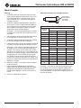
Description
The 882 Conduit Bender is intended to bend EMT
(electrical metallic tubing). The 882CB Conduit Bender
is intended to bend EMT, IMC (intermediate metallic
conduit), GRC (galvanized rigid conduit), and Schedule
40 Pipe. Bending shoes are available to accommodate
1-1/4" through 2" conduit and pipe.
The bender is to be coupled to any Greenlee hydraulic
pump capable of developing 10,000 psi (689.5 bar).
Suggested models include:
Hand Pump: 755
Electric Pump (120 V): 960 SAPS
975
Electric Pump (220 V): 976-22FS
976-22PS
Safety
Safety is essential in the use and maintenance of
Greenlee tools and equipment. This instruction manual
and any markings on the tool provide information for
avoiding hazards and unsafe practices related to the
use of this tool. Observe all of the safety information
provided.
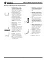
Purpose of this Manual
This manual is intended to familiarize all personnel with
the safe operation and maintenance procedures for the
following Greenlee tools:
882 and 882CB Hydraulic Benders
Keep this manual available to all personnel.
Replacement manuals are available upon request at no
charge at www.greenlee.com.
All specications are nominal and may change as design
improvements occur. Greenlee Tools, Inc. shall not be liable for
damages resulting from misapplication or misuse of its products.
KEEP THIS MANUAL
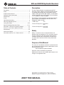
Table of Contents
Description .................................................................... 2
Safety ............................................................................ 2
Purpose of this Manual ................................................. 2
Important Safety Information ........................................ 3
Identication .................................................................. 4
Setup ............................................................................. 5
Operating Instructions ................................................... 6
Glossary of Bending Terms ........................................... 7
Laying Out Bends ..................................................... 8-10
Special Bending Information Chart ........................ 11-13
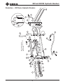
Illustration—882 Series Hydraulic Benders ................. 43
Parts List—882 Series Hydraulic Benders .................. 44
Shoe Groups ............................................................... 45
Attachment Groups ..................................................... 46
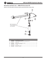
Illustration and Parts List—Conversion Kit .................. 47

882 and 882CB Hydraulic Benders
Greenlee Tools, Inc. 4455 Boeing Dr. • Rockford, IL 61109-2988 USA • 815-397-7070
3
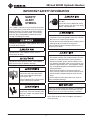
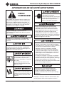
IMPORTANT SAFETY INFORMATION
SAFETY
ALERT
SYMBOL
This symbol is used to call your attention to hazards
or unsafe practices which could result in an injury or
property damage. The signal word, dened below,
indicates the severity of the hazard. The message
after the signal word provides information for pre-
venting or avoiding the hazard.
Immediate hazards which, if not avoided, WILL result
in severe injury or death.
Hazards which, if not avoided, COULD result in
severe injury or death.
Hazards or unsafe practices which, if not avoided,
MAY result in injury or property damage.
Read and understand all of the
instructions and safety information
in this manual before operating or
servicing this tool.
Failure to observe this warning could
result in severe injury or death.
Pinch points:
Keep hands away from bending shoe,
follow bar, saddle, and conduit when
bender is in use.
Wear eye protection when operating
this tool.
Failure to wear eye protection could
result in serious eye injury from ying
debris and hydraulic oil.
• Do not stand in direct line with the hydraulic ram. A
component failure could propel parts with sufcient
force to cause severe injury or death.
• Do not operate while wearing loose clothing. Loose
clothing could get caught in moving parts.
Failure to observe these warnings could result in
severe injury or death.
• Conduit moves rapidly as it is bent. The path of
the conduit must be clear of obstructions. Be sure
clearance is adequate before starting the bend.
• Inspect the bender, pump, and hose before each
use. Replace damaged, worn or missing parts with
Greenlee replacement parts. A damaged or improp-
erly assembled component could break and strike
nearby personnel.
• Some of the bender parts and accessories are
heavy and may require more than one person to lift
and assemble. Improper lifting can result in back
injury.
Failure to observe these precautions may result in
injury or property damage.
Make sure all hose ttings are properly seated before
starting the bend. Incomplete connections may not
allow the ram to retract after the bend is complete.
Note: Keep all decals clean and legible, and replace
when necessary.

882 and 882CB Hydraulic Benders
Greenlee Tools, Inc. 4455 Boeing Dr. • Rockford, IL 61109-2988 USA • 815-397-7070
4
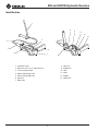
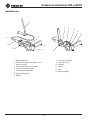
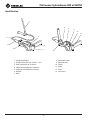
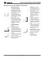
Identification
1. Hydraulic Pump
2. Hose Unit, 3/8" x 6 ft, High-Pressure
3. 12-ton Hydraulic Ram
4. Upper Connecting Plate
5. Lower Connecting Plate
6. Hitch Pin
7. Roller Unit
8. Yoke Pin
9. Saddle Pin
10. Yoke
11. Shoe
12. Saddle
13. Follow Bar
1
4
6
7
5
2
3
8
9
11
12
13
10

882 and 882CB Hydraulic Benders
Greenlee Tools, Inc. 4455 Boeing Dr. • Rockford, IL 61109-2988 USA • 815-397-7070
5
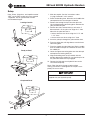
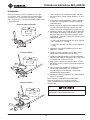
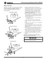
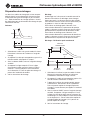
Setup
Note: Shoes, follow bars, and saddles marked
“EMT” are for EMT conduit only. Parts marked
“Rigid/IMC” are for rigid and IMC conduit,
and Schedule 40 pipe.
Loading Conduit
Ready to Bend
Completed Bend
1. Mark the conduit. See the instructions under
“Laying Out Bends” in this manual.
2. Select the bending shoe, follow bar, and saddle that
correspond to the size and type of conduit.
3. Remove the locking hitch pin from the roller unit.
Lift the hinged upper connecting plate. Remove the
yoke pin from the yoke.
4. Position the shoe, lettered side up, so that the 1"
diameter hole is in the yoke slot. Align the 1" shoe
hole with the yoke hole that is:
• farthest from the ram when using the 1-1/4" and
1-1/2" shoe
• closest to the ram when using the 2" shoe
5. Insert the yoke pin through the yoke and the shoe.
6. Place the follow bar, with legs down, over the lower
connecting plate.
7. Place the conduit into the follow bar. Slip the saddle
over the conduit and pin the saddle to the shoe with
the saddle pin.
8. Lower the upper connecting plate over the roller pin
and replace the locking hitch pin.
9. Align the bending mark on the conduit with the
outside edge of the saddle. Be sure that the pins for
the yoke and saddle are fully engaged.
10. Connect the high-pressure hydraulic hose to the
ram and to the pump.
Note: Clean the quick-change couplers before
making connections. Hand-tighten the couplers com-
pletely. Do not use tools.
Follow the instructions and safety information
supplied with your hydraulic pump.

882 and 882CB Hydraulic Benders
Greenlee Tools, Inc. 4455 Boeing Dr. • Rockford, IL 61109-2988 USA • 815-397-7070
6
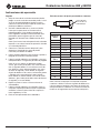
Operating Instructions
Bending
1. Loosen the ram travel scale nut; set the ram travel
scale, which is read at the edge of the block, to
zero. Tighten the nut. See the illustration under
“Ram Travel Table for Common Bends.”
2. Use the hydraulic pump and advance the ram until
the shoe contacts the conduit and the conduit is
seated in the follow bar. Check the placement of the
conduit to be sure that the bending mark is aligned
with the outside edge of the saddle.
Note: For specific pump operating instructions, see
the instruction manual supplied with the hydraulic
pump.
3. Consult the “Ram Travel Table” to nd the amount
of ram travel necessary to accomplish the bend.
4. Use the hydraulic pump to advance the ram by the
necessary amount of ram travel.
5. Release the hydraulic pressure at the pump and
move the conduit to the next bending position.
Note: If making an offset bend, rotate the conduit
180° before making the second bend. If making a
three-bend saddle, rotate the conduit 180° before
making the second and third bends; the second
bend angle is twice the number of degrees and
requires more ram travel than the first and third
bends. If making a 4-bend saddle, rotate the conduit
before making the second and fourth bends.
6. Repeat steps 2–5 until the last bend is made.
7. Release the hydraulic pressure at the pump.
Remove the locking hitch pin to release the upper
connecting plate. Lift the plate clear of the shoe,
follow bar, and saddle.
8. Remove the conduit from the bender.
Ram Travel Table for Common Bends
Ram Travel:
Read Scale at
Edge of Block
Ram Travel (approximate)
Angle of
Bend
FOR IMC/RIGID CONDUIT
1-1/4" 1-1/2" 2"
5° 2-1/8" 7/8" 13/16"
10° 2-3/8" 1-1/16" 1-1/16"
15° 2-5/8" 1-3/8" 1-7/16"
30° 3-5/16" 2-1/16" 2-1/2"
45° 4-1/8" 2-7/8" 3-9/16"
60° 4-15/16" 3-11/16" 4-5/8"
90° 6-1/4" 5-13/16" 6-11/16"
Angle of
Bend
FOR EMT CONDUIT
1-1/4" 1-1/2" 2"
5° 2-1/16" 7/8" 1-3/8"
10° 2-1/4" 1-1/8" 1-5/8"
15° 2-7/16" 1-5/16" 1-7/8"
30° 3-1/8" 2-1/16" 2-5/8"
45° 3-7/8" 2-7/8" 3-3/8"
60° 4-5/8" 3-11/16" 4-3/16"
90° 6-3/16" 5-3/8" 5-1/2"
Note: Consult the table that corresponds to the type
of conduit to be bent. Find the degree of bend in the left
most column and find the size of conduit to the right.
The number shown on the table is the amount of ram
travel needed.

882 and 882CB Hydraulic Benders
Greenlee Tools, Inc. 4455 Boeing Dr. • Rockford, IL 61109-2988 USA • 815-397-7070
7
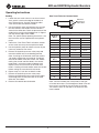
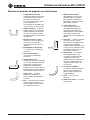
Glossary of Bending Terms with Illustrations
1. amount of offset — the dis-
tance that the conduit or pipe
must be re-routed to avoid an
obstruction; see offset in this
glossary and “Offset” bending
instructions in this manual
2. back-to-back bend — any
U-shaped bend formed by
two parallel 90° bends with a
straight section of conduit or
pipe between the bends
3. center-to-center distance —
the distance between the suc-
cessive bends that make
up an offset or a three-bend
saddle
4. depth of offset — same as
amount of offset
5. height of offset — same as
amount of offset
6. leg length — the distance from
the end of a horizontal section
of conduit or pipe to the bend;
measured from the end to the
center line, inside edge, or
outside edge of the conduit
or pipe
7. 90° bend — any bend that
changes the direction of the
conduit or pipe by 90 degrees
8. O.D. — the size of any piece of
conduit or pipe as measured by
its outside diameter
9. offset bend — two bends with
the same degree of bend; used
to avoid an obstruction block-
ing the run of the conduit or
pipe
10. ram travel — the distance that
the ram of hydraulic bender
moves to accomplish a particu-
lar bend; inches of ram travel
are proportionate to degrees of
bend
11. rise — the distance from the
end of a vertical section of
conduit or pipe to the bend;
measured from the end to the
center line, inside edge, or
outside edge of the conduit or
pipe
12. shrink — the amount of conduit
“lost” when laying out an
offset bend working toward an
obstruction; see the detailed
explanation under “Offset”
bending in this manual
13. springback — the amount,
measured in degrees, that
a conduit or pipe tends to
straighten after being bent
14. stub — same as rise
15. stub-up — same as rise

882 and 882CB Hydraulic Benders
Greenlee Tools, Inc. 4455 Boeing Dr. • Rockford, IL 61109-2988 USA • 815-397-7070
8
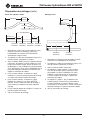
Laying Out Bends
The following drawings and bending charts are intended
to provide the information necessary to accomplish the
most common types of bends. The “Special Bending
Information Chart” contains information for the most
commonly needed bending dimensions.
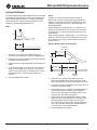
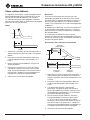
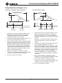
Stubs
MARK
Y
HEIGHT
ANGLE
1. Select the size and type of conduit to be bent.
Determine the height of stub and the angle of bend.
2. Find the chart that corresponds to the type and size
of conduit selected in Step 1.
3. Under the column labeled ANGLE, nd the angle of
bend.
4. Find the row labeled Y. In the row at the top of the
page, nd the height (H) of the stub. The number
shown at this intersection is the dimension Y. Place
the bending mark Y inches from the end of the
conduit.
5. See the bending instructions.
Offset
An offset is used to route the conduit around an
obstruction. To make an offset, two equal bends are
required. The distance between the two bends is the
center-to-center distance. This is represented by L1 in
the bending tables.
When working past an obstruction, it is necessary to
determine the location of the rst bend. The center-to-
center distance is then used to nd the location of the
second bend.
When working toward an obstruction, it is necessary to
determine the location of the second bend. The center-
to-center distance is then used to nd the location of
the rst bend.
Offsets: Working Past an Obstruction
BENDING
MARK 2
BENDING
MARK 1
LENGTH – X
LENGTH
L1
ANGLE
HEIGHT
START OF
FIRST BEND
1. Select the size and type of conduit to be bent.
Measure the height of the obstruction and the dis-
tance labeled LENGTH. Select the angle to be used.
2. Find the chart that corresponds to the type and size
of conduit selected in Step 1.
3. To the right of the size and type of conduit, nd the
dimension labeled X. Subtract X from LENGTH.
Place the rst bending mark (Bending Mark 1) this
distance from the end of the conduit.
4. Under the column labeled ANGLE, nd the angle
of bend. Find the row labeled L1. In the row at the
top of the page, nd the height (H) of the offset.
The number at this intersection is the dimension L1.
Place the second bending mark (Bending Mark 2)
L1 inches from the rst bending mark.
5. See the bending instructions.

882 and 882CB Hydraulic Benders
Greenlee Tools, Inc. 4455 Boeing Dr. • Rockford, IL 61109-2988 USA • 815-397-7070
9
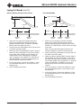
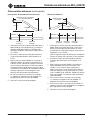
Laying Out Bends (cont’d)
Offsets: Working Toward an Obstruction
BENDING
MARK 1
BENDING
MARK 2
LENGTH TO END OF SECOND BEND
LENGTH – Z L1
HEIGHT
ANGLE
1. Select the size and type of conduit to be bent.
Measure the height of the obstruction and the
distance labeled LENGTH TO END OF SECOND
BEND. Select the angle to be used.
2. Find the chart that corresponds to the type and size
of conduit selected in Step 1.
3. Under the column labeled ANGLE, nd the angle of
bend. Find the row labeled Z. In the row at the top
of the page, nd the height (H) of the offset. The
number shown at this intersection is the dimen-
sion Z. Subtract Z from LENGTH TO THE END OF
SECOND BEND. Place the rst bending mark this
distance from the end of the conduit.
4. In the same column, nd the row labeled L1. Place
the second bending mark L1 inches from the rst
bending mark.
5. See the bending instructions.
Three-Bend Saddle
BENDING
MARK 2
BENDING
MARK 1
BENDING
MARK 3
LENGTH – Z
LENGTH TO CENTER
L1 L2
ANGLE
HEIGHT
1. Select the size and type of conduit to be bent.
Measure the height of the obstruction and the
distance from the end of the conduit to the center
(LENGTH TO CENTER) of the bend. Select the angle
to be used.
Note: The second bend angle will be twice the
number of degrees as the first and third bends.
2. Find the chart that corresponds to the type and size
of conduit selected in Step 1.
3. Under the column labeled ANGLE, nd the angle of
bend needed. Find the row labeled Z. In the row at
the top of the page, nd the height (H) of the offset.
The number shown at this intersection is Z. Subtract
Z from the LENGTH TO CENTER. Place the rst
bending mark this distance from the end of the
conduit.
4. In the same column, nd the row labeled L1. Place
the second bending mark L1 inches from the rst
bending mark.
5. In the same column, nd the row labeled L2. Place
the third bending mark L2 inches from the second
bending mark.
6. See the bending instructions.

882 and 882CB Hydraulic Benders
Greenlee Tools, Inc. 4455 Boeing Dr. • Rockford, IL 61109-2988 USA • 815-397-7070
10
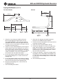
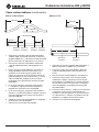
Laying Out Bends (cont’d)
Four-Bend Saddle
BENDING
MARK 2
BENDING
MARK 1
BENDING
MARK 4
BENDING
MARK 3
LENGTH – Z
LENGTH
STRAIGHT
SECTION
L1 L1
ANGLE
HEIGHT
L2 + STRAIGHT SECTION
U-Bends
LENGTH
HEIGHT
Y L1
BENDING
MARK 1
BENDING
MARK 2
1. Select the size and type of conduit to be bent.
Measure the height of the obstruction, the dis-
tance labeled LENGTH, and the distance labeled
STRAIGHT SECTION. Select the angle to be used.
2. Find the chart that corresponds to the type and size
of conduit selected in Step 1.
3. Under the column labeled ANGLE, nd the angle of
bend needed. Find the row labeled Z. In the row at
the top of the page, nd the height (H) of the offset.
The number shown at this intersection is Z. Subtract
Z from the LENGTH. Place the rst bending mark
this distance from the end of the conduit.
4. In the same column, nd the row labeled L1. Place
the second bending mark L1 inches from the rst
bending mark.
5. In the same column, nd the row labeled L2. Add L2
to the STRAIGHT SECTION. Place the third bending
mark this distance from the rst bending mark.
6. Make the nal bending mark L1 inches from the
third bending mark.
7. See the bending instructions.
1. Select the size and type of conduit to be bent.
Determine the LENGTH and the HEIGHT.
2. Find the chart that corresponds to the type and size
of conduit selected in Step 1.
3. Under the column labeled ANGLE, nd 90°.
4. Find the row labeled Y. In the row at the top of the
page, nd the height (H) that corresponds to the
LENGTH. The number shown at this intersection is
the dimension Y. Place the bending mark Y inches
from the end of the conduit.
5. Find the row labeled L1, and go to the right to nd
the height (H) that corresponds to the HEIGHT. The
number shown at this intersection is the dimension
L1. Place the second bending mark L1 inches from
the rst mark.
6. See the bending instructions.

882 and 882CB Hydraulic Benders
Greenlee Tools, Inc. 4455 Boeing Dr. • Rockford, IL 61109-2988 USA • 815-397-7070
11
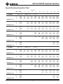
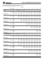
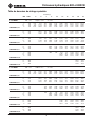
Y 15.00 0.41 8.14 15.87 23.59 31.32 39.05 50.64 62.23 85.41 131.78
L1 15.00 7.72 15.44 23.17 30.90 38.63 46.35 57.94 69.54 92.72 139.08
L2 15.00 9.66 17.39 25.12 32.84 40.57 48.30 59.89 71.48 94.66 141.03
Z 15.00 12.84 20.30 27.77 35.23 42.70 50.16 61.36 72.55 94.95 139.73
MINIMUM H=1.39
Y 22.50 3.58 8.81 14.03 19.26 24.49 32.33 40.17 55.84 87.20
L1 22.50 10.41 15.64 20.87 26.09 31.32 39.16 47.00 62.68 94.03
L2 22.50 13.33 18.56 23.78 29.01 34.24 42.08 49.92 65.59 96.95
Z 22.50 16.03 20.86 25.69 30.52 35.35 42.59 49.83 64.32 93.29
MINIMUM H=2.44
Y 30.00 1.08 5.08 9.08 13.08 17.08 23.08 29.08 41.08 65.08
L1 30.00 7.91 11.91 15.91 19.91 23.91 29.91 35.91 47.91 71.91
L2 30.00 11.80 15.80 19.80 23.80 27.80 33.80 39.80 51.80 75.80
Z 30.00 14.33 17.79 21.26 24.72 28.19 33.38 38.58 48.97 69.76
MINIMUM H=3.70
Y 45.00 0.92 3.75 6.58 9.41 13.65 17.89 26.38 43.35
L1 45.00 10.99 13.82 16.65 20.89 25.14 33.62 50.59
L2 45.00 16.83 19.66 22.49 26.73 30.97 39.46 56.43
Z 45.00 17.58 19.58 21.58 24.58 27.58 33.58 45.58
MINIMUM H=6.77
Y 60.00 0.66 2.97 5.27 8.74 12.20 19.13 32.99
L1 60.00 13.06 16.52 19.99 26.91 40.77
L2 60.00 20.84 24.30 27.77 34.69 48.55
Z 60.00 18.93 20.66 22.39 25.86 32.78
MINIMUM H=10.39
Y 90.00 0.40 3.40 6.40 12.40 24.39
L1 90.00 20.81 32.81
L2 90.00 32.48 44.48
Z 90.00 18.28 18.28
MINIMUM H=18.28
Y 15.00 7.18 14.91 22.64 30.36 38.09 49.68 61.27 84.45 130.82
L1 15.00 7.71 15.44 23.17 30.90 38.62 46.35 57.94 69.53 92.72 139.08
L2 15.00 9.89 17.62 25.34 33.07 40.80 48.52 60.12 71.71 94.89 141.25
Z 15.00 13.47 20.93 28.40 35.86 43.33 50.79 61.99 73.18 95.57 140.36
MINIMUM H=1.55
Y 22.50 2.71 7.93 13.16 18.39 23.61 31.45 39.29 54.97 86.33
L1 22.50 10.41 15.64 20.86 26.09 31.31 39.15 46.99 62.67 94.03
L2 22.50 13.67 18.90 24.12 29.35 34.57 42.41 50.25 65.93 97.29
Z 22.50 16.78 21.61 26.44 31.26 36.09 43.34 50.58 65.06 94.03
MINIMUM H=2.73
Y 30.00 0.22 4.22 8.22 12.22 16.22 22.22 28.22 40.22 64.22
L1 30.00 11.90 15.90 19.90 23.90 29.90 35.90 47.90 71.90
L2 30.00 16.24 20.24 24.24 28.24 34.24 40.24 52.24 76.24
Z 30.00 18.66 22.12 25.59 29.05 34.25 39.44 49.84 70.62
MINIMUM H=4.13
Y 45.00 0.00 2.83 5.65 8.48 12.72 16.97 25.45 42.42
L1 45.00 10.96 13.78 16.61 20.86 25.10 33.58 50.55
L2 45.00 17.48 20.30 23.13 27.37 31.62 40.10 57.07
Z 45.00 18.70 20.70 22.70 25.70 28.70 34.70 46.70
MINIMUM H=7.56
Y 60.00 1.93 4.24 7.70 11.17 18.10 31.95
L1 60.00 12.96 16.43 19.89 26.82 40.68
L2 60.00 21.66 25.12 28.58 35.51 49.37
Z 60.00 20.33 22.06 23.80 27.26 34.19
MINIMUM H=11.61
Y 90.00 2.01 5.01 11.01 23.01
L1 90.00 20.44 32.44
L2 90.00 33.48 45.48
Z 90.00 20.42 20.42
MINIMUM H=20.42
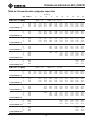
DIM ANGLE 2" 4" 6" 8" 10" 12" 15" 18" 24" 36"
1-1/4 EMT Dia. = 1.51 Radius = 7.43 X = 3.42
1-1/2 EMT Dia. = 1.74 Radius = 8.3 X = 3.82
HEIGHT (H)
Special Bending Information Chart

882 and 882CB Hydraulic Benders
Greenlee Tools, Inc. 4455 Boeing Dr. • Rockford, IL 61109-2988 USA • 815-397-7070
12
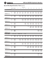
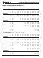
Y 15.00 6.01 13.74 21.47 29.19 36.92 48.51 60.10 83.29 129.65
L1 15.00 7.71 15.44 23.17 30.90 38.62 46.35 57.94 69.53 92.71 139.08
L2 15.00 10.22 17.95 25.68 33.41 41.13 48.86 60.45 72.04 95.23 141.59
Z 15.00 13.92 21.38 28.85 36.31 43.78 51.24 62.44 73.63 96.02 140.81
MINIMUM H=1.67
Y 22.50 1.74 6.97 12.19 17.42 22.65 30.48 38.32 54.00 85.36
L1 22.50 10.40 15.63 20.86 26.08 31.31 39.15 46.99 62.67 94.02
L2 22.50 14.17 19.40 24.62 29.85 35.07 42.91 50.75 66.43 97.79
Z 22.50 17.40 22.23 27.06 31.89 36.72 43.96 51.20 65.69 94.66
MINIMUM H=2.96
Y 30.00 3.30 7.30 11.30 15.30 21.30 27.30 39.30 63.30
L1 30.00 11.88 15.88 19.88 23.88 29.88 35.88 47.88 71.88
L2 30.00 16.90 20.90 24.90 28.90 34.90 40.90 52.90 76.90
Z 30.00 19.46 22.93 26.39 29.85 35.05 40.25 50.64 71.42
MINIMUM H=4.53
Y 45.00 1.86 4.68 7.51 11.76 16.00 24.48 41.45
L1 45.00 13.73 16.56 20.80 25.04 33.53 50.50
L2 45.00 21.26 24.09 28.33 32.58 41.06 58.03
Z 45.00 21.87 23.87 26.87 29.87 35.87 47.87
MINIMUM H=8.40
Y 60.00 0.81 3.12 6.58 10.05 16.98 30.83
L1 60.00 16.29 19.75 26.68 40.54
L2 60.00 26.33 29.80 36.72 50.58
Z 60.00 23.66 25.40 28.86 35.79
MINIMUM H=12.99
Y 90.00 0.38 3.38 9.38 21.38
L1 90.00 19.88 31.88
L2 90.00 34.95 46.95
Z 90.00 23.11 23.11
MINIMUM H= 23.11
Y 15.00 7.31 15.04 22.77 30.50 38.22 49.82 61.41 84.59 130.95
L1 15.00 7.72 15.44 23.17 30.90 38.63 46.35 57.94 69.54 92.72 139.08
L2 15.00 9.67 17.40 25.13 32.85 40.58 48.31 59.90 71.49 94.67 141.04
Z 15.00 13.38 20.85 28.31 35.77 43.24 50.70 61.90 73.09 95.49 140.27
MINIMUM H=1.53
Y 22.50 2.85 8.07 13.30 18.53 23.75 31.59 39.43 55.11 86.47
L1 22.50 10.41 15.64 20.87 26.09 31.32 39.16 47.00 62.68 94.03
L2 22.50 13.35 18.57 23.80 29.03 34.25 42.09 49.93 65.61 96.97
Z 22.50 16.58 21.41 26.24 31.06 35.89 43.13 50.38 64.86 93.83
MINIMUM H=2.65
Y 30.00 0.39 4.39 8.39 12.39 16.39 22.39 28.39 40.39 64.39
L1 30.00 7.91 11.91 15.91 19.91 23.91 29.91 35.91 47.91 71.91
L2 30.00 11.82 15.82 19.82 23.82 27.82 33.82 39.82 51.82 75.82
Z 30.00 14.88 18.35 21.81 25.27 28.74 33.93 39.13 49.52 70.31
MINIMUM H=3.98
Y 45.00 0.27 3.10 5.92 8.75 13.00 17.24 25.72 42.69
L1 45.00 10.99 13.82 16.65 20.89 25.13 33.62 50.59
L2 45.00 16.86 19.69 22.52 26.76 31.00 39.49 56.46
Z 45.00 18.14 20.14 22.14 25.14 28.14 34.14 46.14
MINIMUM H=7.17
Y 60.00 0.02 2.33 4.64 8.10 11.56 18.49 32.35
L1 60.00 13.05 16.52 19.98 26.91 40.77
L2 60.00 20.88 24.34 27.80 34.73 48.59
Z 60.00 19.50 21.24 22.97 26.43 33.36
MINIMUM H=10.90
Y 90.00 2.75 5.75 11.75 23.75
L1 90.00 20.79 32.79
L2 90.00 32.53 44.53
Z 90.00 18.89 18.89
MINIMUM H=18.89
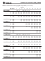
DIM ANGLE 2" 4" 6" 8" 10" 12" 15" 18" 24" 36"
2 EMT Dia. = 2.2 Radius = 9.59 X = 3.93
1-1/4 IMC/RIGID Dia. = 1.66 Radius = 7.47 X = 3.95
HEIGHT (H)
Special Bending Information Chart (cont’d)

882 and 882CB Hydraulic Benders
Greenlee Tools, Inc. 4455 Boeing Dr. • Rockford, IL 61109-2988 USA • 815-397-7070
13
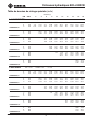
Y 15.00 6.62 14.34 22.07 29.80 37.52 49.12 60.71 83.89 130.25
L1 15.00 7.71 15.44 23.17 30.90 38.62 46.35 57.94 69.53 92.72 139.08
L2 15.00 9.94 17.67 25.39 33.12 40.85 48.58 60.17 71.76 94.94 141.31
Z 15.00 13.75 21.22 28.68 36.14 43.61 51.07 62.27 73.46 95.86 140.64
MINIMUM H=1.63
Y 22.50 2.23 7.46 12.68 17.91 23.13 30.97 38.81 54.49 85.85
L1 22.50 10.41 15.64 20.86 26.09 31.31 39.15 46.99 62.67 94.03
L2 22.50 13.75 18.97 24.20 29.43 34.65 42.49 50.33 66.01 97.37
Z 22.50 17.09 21.92 26.75 31.57 36.40 43.64 50.89 65.37 94.34
MINIMUM H=2.84
Y 30.00 3.77 7.77 11.77 15.77 21.77 27.77 39.77 63.77
L1 30.00 11.90 15.90 19.90 23.90 29.90 35.90 47.90 71.90
L2 30.00 16.35 20.35 24.35 28.35 34.35 40.35 52.35 76.35
Z 30.00 19.00 22.46 25.93 29.39 34.59 39.78 50.17 70.96
MINIMUM H=4.30
Y 45.00 2.40 5.23 8.06 12.30 16.54 25.03 42.00
L1 45.00 10.95 13.78 16.60 20.85 25.09 33.58 50.55
L2 45.00 17.62 20.45 23.28 27.52 31.77 40.25 57.22
Z 45.00 19.09 21.09 23.09 26.09 29.09 35.09 47.09
MINIMUM H=7.84
Y 60.00 1.49 3.80 7.27 10.73 17.66 31.51
L1 60.00 12.94 16.41 19.87 26.80 40.66
L2 60.00 21.84 25.31 28.77 35.70 49.56
Z 60.00 20.79 22.53 24.26 27.72 34.65
MINIMUM H=12.01
Y 90.00 1.50 4.50 10.50 22.50
L1 90.00 20.35 32.35
L2 90.00 33.70 45.70
Z 90.00 21.05 21.05
MINIMUM H=21.05
Y 15.00 5.06 12.79 20.52 28.25 35.97 47.56 59.16 82.34 128.70
L1 15.00 7.71 15.44 23.17 30.90 38.62 46.35 57.94 69.53 92.72 139.08
L2 15.00 10.11 17.83 25.56 33.29 41.02 48.74 60.33 71.93 95.11 141.47
Z 15.00 14.47 21.93 29.40 36.86 44.33 51.79 62.99 74.18 96.58 141.36
MINIMUM H=1.81
Y 22.50 0.93 6.16 11.38 16.61 21.84 29.68 37.52 53.19 84.55
L1 22.50 10.41 15.63 20.86 26.08 31.31 39.15 46.99 62.67 94.03
L2 22.50 13.99 19.22 24.45 29.67 34.90 42.74 50.58 66.26 97.61
Z 22.50 17.89 22.72 27.55 32.38 37.21 44.45 51.69 66.18 95.15
MINIMUM H=3.15
Y 30.00 2.58 6.58 10.58 14.58 20.58 26.58 38.58 62.58
L1 30.00 11.89 15.89 19.89 23.89 29.89 35.89 47.89 71.89
L2 30.00 16.67 20.67 24.67 28.67 34.67 40.67 52.67 76.67
Z 30.00 19.89 23.35 26.82 30.28 35.48 40.68 51.07 71.85
MINIMUM H=4.75
Y 45.00 1.25 4.08 6.91 11.15 15.39 23.88 40.85
L1 45.00 13.75 16.58 20.82 25.06 33.55 50.52
L2 45.00 20.93 23.76 28.00 32.24 40.73 57.70
Z 45.00 22.17 24.17 27.17 30.17 36.17 48.17
MINIMUM H=8.61
Y 60.00 0.30 2.61 6.07 9.54 16.46 30.32
L1 60.00 16.34 19.80 26.73 40.59
L2 60.00 25.91 29.37 36.30 50.16
Z 60.00 23.81 25.55 29.01 35.94
MINIMUM H=13.12
Y 90.00 0.07 3.07 9.07 21.07
L1 90.00 20.08 32.08
L2 90.00 34.43 46.43
Z 90.00 22.88 22.88
MINIMUM H=22.88
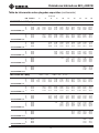
2 IMC/RIGID Dia. = 2.375 Radius = 9.14 X = 4.6
DIM ANGLE 2" 4" 6" 8" 10" 12" 15" 18" 24" 36"
1-1/2 IMC/RIGID Dia. = 1.9 Radius = 8.5 X = 4.05
HEIGHT (H)
Special Bending Information Chart (cont’d)

882 and 882CB Hydraulic Benders
Greenlee Tools, Inc. 4455 Boeing Dr. • Rockford, IL 61109-2988 USA • 815-397-7070
14

MANUAL DE INSTRUCCIONES
Lea y entienda todas las instrucciones y la
información sobre seguridad que aparecen en
este manual, antes de manejar esta herramienta o
darle mantenimiento.
Registre este producto en www.greenlee.com
99971690 © 2019 Greenlee Tools, Inc. IM 975 REV 15 2/19
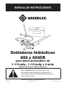
Dobladoras hidráulicas
882 y 882CB
para tubos portacables de
1-1/4 pulg., 1-1/2 pulg. y 2 pulg.
Números de Serie FT 16000 y superiores

Dobladoras hidráulicas 882 y 882CB
Greenlee Tools, Inc. 4455 Boeing Dr. • Rockford, IL 61109-2988 USA • 815-397-7070
16
Descripción
La Dobladora 882 para tubos portacables está diseñada
para doblar EMT (tubería eléctrica metálica). La
Dobladora 882CB para tubos portacables está diseñada
para doblar tubos EMT, IMC (tubo portacables metálico
intermedio), GRC (tubo portacables rígido galvanizado),
y tubería 40. Hay disponibles zapatas de plegado para
el uso con tubos portacables y tubería desde 1-1/4
pulg. a 2 pulg.
La dobladora debe acoplarse a cualquier bomba
hidráulica Greenlee, capaz de lograr presiones de hasta
10.000 libras por pulgada
2
(689,5 bar) Los modelos
sugeridos incluyen:
Bomba de mano: 755
Bomba eléctrica (120 V): 960 SAP
975
Bomba eléctrica (220 V): 976-22FS
976-22PS
Acerca de la seguridad
Es fundamental observar métodos seguros al utilizar
y dar mantenimiento a las herramientas y equipo
Greenlee. Este manual de instrucciones y todas
las marcas que ostenta la herramienta le ofrecen la
información necesaria para evitar riesgos y hábitos
poco seguros relacionados con su uso. Siga toda la
información sobre seguridad que se proporciona.
Propósito de este manual
Este manual tiene como propósito familiarizar a todo
el personal con los procedimientos de operación y
mantenimiento seguros para las siguientes herramientas
Greenlee:
Dobladoras hidráulicas 882 y 882CB
Manténgalo siempre al alcance de todo el personal.
Altre copie di questo manuale sono disponibili
gratuitamente su richiesta al sito www.greenlee.com.
Todas las especicaciones son nominales y pueden cambiar cuando
se realicen mejoras en el diseño. Greenlee Tools, Inc. no será
responsable por daños que resulten de la aplicación o uso indebidos
de sus productos.
CONSERVE ESTE MANUAL
Índice
Descripción ................................................................. 16
Acerca de la seguridad ................................................ 16
Propósito de este manual ........................................... 16
Información importante sobre seguridad .................... 17
Identicación ............................................................... 18
Instalación ................................................................... 19
Instrucciones de operación ......................................... 20
Glosario de términos de plegado ................................ 21
Cómo realizar dobleces ..........................................22-24
Tabla de información
sobre plegados especiales .....................................25-27
Ilustración — Dobladoras hidráulicas serie 882 .......... 43
Lista de piezas —
Dobladoras hidráulicas serie 882 ............................... 44
Grupos de zapatas ...................................................... 45
Grupos de aditamentos ............................................... 46
Ilustración y lista de piezas —
Conjunto para conversión ........................................... 47

Dobladoras hidráulicas 882 y 882CB
Greenlee Tools, Inc. 4455 Boeing Dr. • Rockford, IL 61109-2988 USA • 815-397-7070
17
IMPORTANTE INFORMACIÓN SOBRE SEGURIDAD
SÍMBOLO DE
ALERTA SOBRE
SEGURIDAD
Este símbolo se utiliza para indicar un riesgo o
práctica poco segura que podría ocasionar lesiones
o daños materiales. Cada uno de los siguientes
términos denota la gravedad del riesgo. El mensaje
que sigue a dichos términos le indica cómo puede
evitar o prevenir ese riesgo.
Peligros inmediatos que, de no evitarse,
OCASIONARÁN graves lesiones o incluso la muerte.
Peligros que, de no evitarse, PODRÍAN OCASIONAR
graves lesiones o incluso la muerte.
Peligro o prácticas peligrosas que, de no evitarse,
PUEDEN OCASIONAR lesiones o daños materiales.
Lea y entienda todas las
instrucciones y la información sobre
seguridad que aparecen en este
manual, antes de manejar esta
herramienta o darle mantenimiento.
De no observarse esta advertencia
podrían sufrirse graves lesiones o
incluso la muerte.
Puntos de aplastamiento:
Mantenga las manos alejadas de
las zapatas de plegado, de la barra
seguidora, de la silla y del tubo
portacables cuando se esté utilizando
la dobladora.
Al operar la dobladora utilice
protectores para ojos.
De no utilizar protectores para
ojos podría sufrir graves lesiones
oculares ocasionadas si el aceite
para aparatos hidráulicos, o restos de
materiales llegaran a saltar.
• No se pare en línea recta con el pistón hidráulico.
Un fallo del componente podría lanzar partes con
suciente fuerza para ocasionar lesiones graves o
la muerte.
• No opere esta dobladora si lleva puesta vestimenta
holgada. La vestimenta holgada podría quedar
atrapada en las partes movibles.
De no observarse estas advertencias podrían sufrirse
lesiones graves o incluso la muerte.
• El tubo portacables se mueve rápidamente
conforme se dobla. La trayectoria del tubo
portacables debe estar libre de obstáculos. Antes
de comenzar a doblar, asegúrese que el espacio
libre sea el adecuado.
• Revise minuciosamente la dobladora, la bomba
y la manguera antes de cada uso. Reemplace los
componentes dañados, gastados o faltantes con
piezas de repuesto de Greenlee. Los componentes
dañados o mal armados pueden quebrarse y
golpear al personal que esté cerca de la unidad.
• Algunas piezas y accesorios de las dobladoras son
pesados y podría necesitarse más de una persona
para levantarlos e instalarlos. El levantamiento
de objetos de manera errónea puede ocasionar
lesiones en la columna.
De no observarse estas precauciones podrían sufrirse
graves lesiones o daños materiales.
Asegúrese que todos los accesorios de las
mangueras estén debidamente asentados antes de
comenzar el doblez. Las conexiones incompletas
podrían impedir que el pistón se retraiga después de
terminar el doblez.
Aviso: Mantenga limpias y legibles todas las
calcomanías y reemplácelas cuando sea necesario.

Dobladoras hidráulicas 882 y 882CB
Greenlee Tools, Inc. 4455 Boeing Dr. • Rockford, IL 61109-2988 USA • 815-397-7070
18
Identificación
1. Bomba hidráulica
2. Unidad de manguera, 3/8 pulg. x 1,8 m,
para alta presión
3. Pistón hidráulico de 12 toneladas
4. Placa superior de conexión
5. Placa inferior de conexión
6. Clavija de enganche
7. Rodillo
8. Clavija de la horquilla
9. Clavija de la silla
10. Horquilla
11. Zapata
12. Silla
13. Barra seguidora
1
4
6
7
5
2
3
8
9
11
12
13
10

Dobladoras hidráulicas 882 y 882CB
Greenlee Tools, Inc. 4455 Boeing Dr. • Rockford, IL 61109-2988 USA • 815-397-7070
19
Instalación
Nota: Las zapatas, las barras seguidoras y las sillas
con la marca “EMT” son para tubo portacables EMT
solamente. Los componentes marcados con “Rigid/
IMC” son para el uso con tubo portacables rígido e IMC,
y para tubería 40.
Carga del tubo portacables
Listo para doblar
Doblez completo
1. Haga una marca en el tubo portacables. Consulte
las instrucciones “Cómo realizar dobleces” en este
manual.
2. Seleccione la zapata plegadora, la barra seguidora,
y la silla que correspondan al tamaño y al tipo de
tubo portacables.
3. Retire la clavija de enganche de bloqueo del rodillo.
Levante la placa de conexión superior articulada.
Retire la clavija de la horquilla de la horquilla misma.
4. Coloque la zapata, con el lado con letras orientado
hacia arriba, de modo que el oricio de 1 pulg. de
diámetro quede en la ranura de la horquilla. Alinee
el oricio de 1 pulg. de la zapata con el oricio de la
horquilla que esté:
• lo más lejos posible del pistón al usar las zapatas
de 1-1/4 pulg. y 1-1/2 pulg.
• lo más cerca posible al pistón al usar la zapata de
2 pulg.
5. Introduzca la clavija de la horquilla a través de la
horquilla y la zapata.
6. Coloque la barra seguidora, con las patas hacia
abajo, sobre la placa inferior de conexión.
7. Coloque el tubo portacables en la barra seguidora.
Deslice la silla sobre el tubo portacables y je la silla
a la zapata con la clavija de la silla.
8. Baje la placa superior de conexión sobre la clavija
del rodillo y vuelva a colocar la clavija de enganche
de sujeción.
9. Alinee la marca de plegado en el tubo portacables
con el borde exterior de la silla. Asegúrese
que las clavijas para la horquilla y la silla estén
completamente enganchadas.
10. Conecte la manguera hidráulica para alta presión al
pistón y a la bomba.
Nota: Limpie los acopladores de cambio rápido
antes de establecer las conexiones. Apriete a
mano completamente los acopladores. No utilice
herramientas.
Siga las instrucciones y la información de seguridad
suministradas con su bomba hidráulica.

Dobladoras hidráulicas 882 y 882CB
Greenlee Tools, Inc. 4455 Boeing Dr. • Rockford, IL 61109-2988 USA • 815-397-7070
20
Instrucciones de operación
Plegado
1. Aoje la tuerca de la escala de carrera del pistón;
ponga a cero la escala de carrera del pistón, la cual
se lee en el borde del bloque. Apriete la tuerca.
Consulte la ilustración bajo “Tabla de carreras del
pistón para dobleces comunes”.
2. Accione la bomba hidráulica y avance el pistón
hasta que la zapata entre en contacto con el
tubo portacables y éste quede asentado en la
barra seguidora. Verique la colocación del tubo
portacables para asegurarse que la marca de
plegado esté alineada con el borde exterior de la
silla.
Nota: Para instrucciones de operación de su bomba
específica, consulte el manual de operación incluido
con la bomba hidráulica.
3. Consulte la “Tabla de carreras del pistón” para
determinar la longitud de carrera de pistón
necesaria para realizar el doblez.
4. Utilice la bomba hidráulica para avanzar el pistón la
longitud necesaria de carrera del pistón.
5. Libere la presión hidráulica en la bomba y mueva el
tubo portacables a la siguiente posición de plegado.
Nota: Si se va a realizar un doblez de compen-
sación, gire el tubo portacables 180° antes de efec-
tuar el segundo doblez. Si va a realizar una silla de
tres dobleces, gire el tubo portacables 180° antes
de hacer el segundo y tercer doblez; el segundo
ángulo de doblez es dos veces el número de grados
y requiere más carrera del pistón que el primer y
tercer doblez. Si intenta realizar una silla de cuatro
dobleces, gire el tubo portacables antes de efectuar
el segundo y el cuarto doblez.
6. Repita los pasos 2 hasta el 5 hasta efectuar el
último doblez.
7. Libere la presión hidráulica en la bomba. Retire la
clavija de sujeción para liberar la placa superior de
conexión. Levante la placa fuera de la zapata, la
barra seguidora y la silla.
8. Retire el tubo portacables de la dobladora.
Tabla de carreras del pistón para dobleces comunes
Carrera del pistón:
Lea la escala en el
borde del bloque
Carrera del pistón (aproximada)
Ángulo de
doblez
PARA TUBERÍA PORTABLES IMC/RIGID
1-1/4" 1-1/2" 2"
5° 2-1/8" 7/8" 13/16"
10° 2-3/8" 1-1/16" 1-1/16"
15° 2-5/8" 1-3/8" 1-7/16"
30° 3-5/16" 2-1/16" 2-1/2"
45° 4-1/8" 2-7/8" 3-9/16"
60° 4-15/16" 3-11/16" 4-5/8"
90° 6-1/4" 5-13/16" 6-11/16"
Ángulo de
doblez
PARA TUBO PORTACABLES EMT
1-1/4" 1-1/2" 2"
5° 2-1/16" 7/8" 1-3/8"
10° 2-1/4" 1-1/8" 1-5/8"
15° 2-7/16" 1-5/16" 1-7/8"
30° 3-1/8" 2-1/16" 2-5/8"
45° 3-7/8" 2-7/8" 3-3/8"
60° 4-5/8" 3-11/16" 4-3/16"
90° 6-3/16" 5-3/8" 5-1/2"
Nota: Consulte la tabla que corresponda al tipo de
conducto a doblar. Encuentre el grado de doblez en la
columna extrema izquierda y encuentre el tamaño del
tubo portacables a la derecha. El número mostrado en
la tabla es la longitud de carrera necesaria del pistón.
La page est en cours de chargement...
La page est en cours de chargement...
La page est en cours de chargement...
La page est en cours de chargement...
La page est en cours de chargement...
La page est en cours de chargement...
La page est en cours de chargement...
La page est en cours de chargement...
La page est en cours de chargement...
La page est en cours de chargement...
La page est en cours de chargement...
La page est en cours de chargement...
La page est en cours de chargement...
La page est en cours de chargement...
La page est en cours de chargement...
La page est en cours de chargement...
La page est en cours de chargement...
La page est en cours de chargement...
La page est en cours de chargement...
La page est en cours de chargement...
La page est en cours de chargement...
La page est en cours de chargement...
La page est en cours de chargement...
La page est en cours de chargement...
La page est en cours de chargement...
La page est en cours de chargement...
La page est en cours de chargement...
La page est en cours de chargement...
-
 1
1
-
 2
2
-
 3
3
-
 4
4
-
 5
5
-
 6
6
-
 7
7
-
 8
8
-
 9
9
-
 10
10
-
 11
11
-
 12
12
-
 13
13
-
 14
14
-
 15
15
-
 16
16
-
 17
17
-
 18
18
-
 19
19
-
 20
20
-
 21
21
-
 22
22
-
 23
23
-
 24
24
-
 25
25
-
 26
26
-
 27
27
-
 28
28
-
 29
29
-
 30
30
-
 31
31
-
 32
32
-
 33
33
-
 34
34
-
 35
35
-
 36
36
-
 37
37
-
 38
38
-
 39
39
-
 40
40
-
 41
41
-
 42
42
-
 43
43
-
 44
44
-
 45
45
-
 46
46
-
 47
47
-
 48
48


Greenlee 882 & 882CB Hydraulic Bender Manuel utilisateur
- Taper
- Manuel utilisateur
- Ce manuel convient également à
dans d''autres langues
Documents connexes
-
Greenlee 881 & 881CT Cam Trak Hydraulic Bender Manuel utilisateur
-
-
-
-
-
-
-
-
-