Greenlee 52093598 REV 0 Manuel utilisateur
- Taper
- Manuel utilisateur

02/2252093598 Rev 00 © 2022 Greenlee Tools, Inc.
INSTRUCTION MANUAL
881GX Cam Track®
Hydraulic Bender
Read and understand all of the instructions and
safety information in this manual before operating
or servicing this tool.
KEEP THIS MANUAL
Español ..............27-52
Français .............53-78

Cam Track® Hydraulic Bender
52093598 Rev 002© 2022 Greenlee Tools, Inc.
KEEP THIS MANUAL
Table of Contents
Safety Symbols Key ...........................................3
General Safety Warnings ....................................4
Tool Specic Safety Information .........................5
Greenlee Contact Information ............................5
Tool Description ..................................................6
Specications .....................................................6
Tool Identication ...............................................7
Decals & Locations .............................................8
Pre-Operation Inspection ...................................9
Tool Set-Up & Operation ............................ 10-13
Calculating Ram Travel for Bend Angle ............ 14
Bending Basics ......................................... 15-19
Special Bending Tables .............................. 20-23
Troubleshooting ................................................24
Storage & Transportation .................................25
Cleaning ..........................................................25
Repair Kit and Accessories .............................26
Service ..............................................................26
Disposal ............................................................26

Cam Track® Hydraulic Bender
352093598 Rev 00 © 2022 Greenlee Tools, Inc.
This symbol means always wear safety
glasses with side shields or goggles
when handling or using this equipment to
reduce the risk of eye injury.
Always wear gloves when handling or
using this equipment to reduce the risk
of injury.
This symbol means read the operator’s
manual carefully before using the
equipment. The operator’s manual
contains important information on
the safe and proper operation of the
equipment.
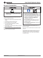
Safety Symbols Key
In this operator’s manual and on the product, safety
symbols and signal words are used to communicate
important safety information. This section is provided
to improve understanding of these signal words and
symbols.
indicates a hazardous situation which, if not avoided,
WILL result in death or serious injury.
indicates a hazardous situation which, if not avoided,
COULD result in death or serious injury.
indicates hazards or unsafe practices which, if not
avoided, MAY result in injury or property damage.
This is the safety alert symbol. It is
used to alert you to potential personal
injury hazards. Obey all safety
messages that follow this symbol to
avoid possible injury or death.
This symbol means always wear safety
footwear to reduce the risk of feet
striking or being struck by objects or
being in contact with thermal or chemical
materials.
This symbol indicates the risk of hands,
ngers or other body parts being crushed.
This symbol indicates the risk of striking
injuries from moving parts of the product.
This symbol indicates the risk of
components breaking free and striking
nearby personnel.
This symbol indicates the risk of
pressurized uid directed at hand or body
parts, causing skin puncture and injection
injuries.
This symbol indicates that the carry case
(or equipment) weight is more than 55 lbs.
(25 kg), use proper lifting technique to
reduce the risk of injury.

Cam Track® Hydraulic Bender
52093598 Rev 004© 2022 Greenlee Tools, Inc.
Safety is essential in the use and maintenance of
Greenlee tools and equipment. This instruction
manual and any markings on the tool provide
information for avoiding hazards and unsafe practices
related to the use of this tool.
Read all safety warnings, instructions, illustrations,
and specications provided with this tool. Failure
to follow all instructions listed below may result in
serious injury.
SAVE ALL WARNINGS AND INSTRUCTIONS FOR
FUTURE REFERENCE.
• Use personal protective equipment (PPE).
Always wear eye protection. Protective
equipment used for appropriate conditions will
reduce personal injuries.
• Use this tool for the manufacturer’s intended
purpose only. Use other than what is instructed
in this manual could result in a hazardous
situation.
• One person must control the work process
and machine operation. Only the operator
should be in the work area when the machine is
operating. This helps reduce the risk of injury.
• Keep handles and grasping surfaces dry,
clean, and free from oil and grease. Slippery
handles and grasping surfaces do not allow
for safe handling and control of the tool in
unexpected situations.
• Some parts and accessories of this tool are
heavy. Use proper lifting techniques to reduce
the risk of injury.
• Stay alert, watch what you are doing and use
common sense when operating this tool. Do
not use this tool while you are tired or under
the inuence of drugs, alcohol, or medication.
A moment of inattention while operating power
tools may result in serious personal injury.
• Keep bystanders a safe distance from the
work area. Additional people close to the
operator increases the risk of injury to themselves
and the operator from distraction or interaction
with equipment.
General Safety Warnings • Do not let familiarity gained from frequent
use of tools allow you to become
complacent and ignore tool safety principles.
A careless action can cause severe injury within
a fraction of a second.
• Do not overreach. Always keep proper footing
and balance. This enables better control of the
tool in unexpected situations.
• Dress properly. Do not wear loose clothing or
jewelry. Keep your hair, clothing, and gloves
away from moving parts. Loose clothes, jewelry
or long hair can be caught in moving parts.
• Store idle tools out of the reach of children
and do not allow persons unfamiliar with
the tool or these instructions to operate the
tool. These tools are dangerous in the hands of
untrained users.
• • Maintain all equipment and accessories. Maintain all equipment and accessories.
Check for misalignment or binding of moving Check for misalignment or binding of moving
parts, breakage of parts and any other condition parts, breakage of parts and any other condition
that may affect the operation. If damaged, that may affect the operation. If damaged,
repair before use. Many accidents are repair before use. Many accidents are
caused by poorly maintained equipment and caused by poorly maintained equipment and
accessories. accessories.
• • Keep work area clean and well lit. Keep work area clean and well lit. Cluttered Cluttered
or dark areas invite accidents. or dark areas invite accidents.
• Daily before use, inspect the tool and correct
any problems before using to reduce the risk
of injury and prevent product damage. If any
problems are found, do not use this tool until
the problems have been xed, failure to follow
these steps increases the risk of injury.
• Proper set up is essential to minimize risk
during use. Set up the tool and work area
according to these procedures to reduce the
risk of injury.
• Follow instructions from this manual when
repairing this tool and use only identical
replacement parts. Use of unauthorized parts
or failure to follow instructions increases the risk
of injury or damage to the tool.
• Tool service must be performed only
by qualified repair personnel. Service
or maintenance performed by unqualied
personnel could result in a risk of injury.

Cam Track® Hydraulic Bender
552093598 Rev 00 © 2022 Greenlee Tools, Inc.
and safer at the rate for which it was designed.
Use of the tool for operations different from those
intended can result in a hazardous situation.
• Do not modify this tool. Modifying the tool in any
manner may result in personal injury and damage
to the tool.
• Do not attempt to open the tool. It contains no
user-serviceable parts.
Greenlee Contact Information
If you have any questions, need to arrange service or
purchase parts or accessories for this Greenlee/HDE
product: Contact your local Greenlee distributor or
Greenlee’s Customer Service Center
Additional copies of this manual are available for
download at www.greenlee.com
Greenlee Customer Service
USA: 1-800-435-0786 | Canada: 800-435-0786
International: 1-815-397-7070
Shipping address:
Greenlee Factory Service Center
4411 Boeing Dr., Rockford, IL 61109
Tool Specific Safety Information
Before operating this tool, read and understand:
• This operator’s manual
• The instructions for any other equipment or
material used with this tool
• Markings on the tool
• Required work-site safety procedures
Failure to follow all instructions and warnings may
result in serious injury.
SAVE ALL WARNINGS AND INSTRUCTIONS FOR
FUTURE REFERENCE.
• Keep your fingers, hands, and other body
parts away from bender, attachments, conduit
and moving parts. Body parts can be struck,
crushed, fractured, or amputated if they become
caught between the attachment or between these
components and any other object.
• Do not bend Aluminum EMT. Conduit may break
causing serious injury.
• Do not stand in a direct line with the follow
bar, hydraulic ram or conduit while bending.
The bender is under high pressure during use
and has the potential to break and throw parts,
causing serious injury.
• Do not alter this product in any manner or
attach any tools that are not specified in this
manual. Use of this bender with accessories and
equipment different from those specied could
result in a hazardous situation.
• High pressure oil easily punctures skin,
causing serious injury, gangrene, or death. Do
not use your hands to check for leaks. Stay away
from pressurized components. Depressurize
hydraulic system before touching the hose/
attachments. If injured, seek medical help
immediately to remove oil.
• Use only Greenlee hoses, attachments, and
accessories in good operating condition
with proper ratings for the tool. Do not alter
products from original design, worn, damaged or
improperly rated equipment can fail and cause
serious personal injury.
• Use proper combination of accessories for the
specific conduit size. Bends will be incorrect
and injury or damage to the tool could result.
• Use the correct tool and accessories for your
application. The correct tool will do the job better

Cam Track® Hydraulic Bender
52093598 Rev 006© 2022 Greenlee Tools, Inc.
Bending Capabilities: ........................................................................ 2-1/2”, 3”, 3-1/2”, and 4” Steel Rigid, IMC, EMT
2-1/2”, 3”, 3-1/2”, and 4” Aluminum Rigid
2-1/2” and 3” Stainless Steel Rigid
2-1/2”, 3”, 3-1/2”, and 4” Schedule 40 pipe
Do not use to bend Aluminum EMT
Storage Box Dimensions (H x L x W): ....................................... 25 in. x 60 in. x 24 in. (63.5cm x 152.4cm x 60.96cm)
Bender Assembly and Accessories in Storage Box Weight: ............................................................ 882 lbs. (400 kg)
Bending Shoe Weights*: ................................................................................................................. 2 ½” – 35 lb. (16kg)
3” – 54 lb. (25kg)
3 ½” – 71 lb. (32kg)
4” – 87 lb. (39kg)
Follow Bar Weights*: ....................................................................................................................... 2 ½” – 22 lb. (10kg)
3” – 30 lb. (14kg)
3 ½” – 47 lb. (21kg)
4” – 63 lb. (29kg)
*Model Estimate
Recommended Hose & Coupler: .................................................................................................. Greenlee CAT 11289
Pump: ............................................................Greenlee hydraulic pump capable of developing 10,000 psi with a usable
oil volume of 6 quarts or more, such as the Greenlee 980 series pumps.
All specifications are nominal and may change as design improvements occur.
Specifications
Tool Description
The 881GX Cam Track® Hydraulic Bender is a bender that can be used to bend 2-1/2”-4” Rigid, IMC and EMT
conduit. This bender can be mounted and operated on the Greenlee Mobile Bending Table (MBT) or operated on the
oor. See catalog for available congurations.
Features
Dedicated 90˚ bending shoe groups containing a shoe, follow bar and saddle.
Extended yoke to reduce time changing accessories.
Lighter follow bars to optimize user ergonomics.
Spring pins to reduce the amount of hitch pins used.
Bending tables

Cam Track® Hydraulic Bender
752093598 Rev 00 © 2022 Greenlee Tools, Inc.
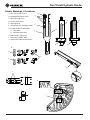
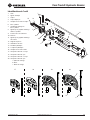
Tool Identification
1. Ram
2. Spring Clip
3. Yoke
4. Extended Yoke
5. Yoke Spring Pin
6. Cylinder Block
7. Cylinder Block Hitch Pins
8. Cylinder Block Hitch Pin Clips
9. Connecting Forks
10. Roller Unit
11. Roller Hitch Pin Clips
12. Piston Support
13. Ram Scale
14. Hydraulic Hose
15. Hydraulic Coupler
16. Saddle Spring Pin
17. 2-1/2 in. Shoe Group
18. 3 in. Shoe Group
19. 3-1/2 in. Shoe Group
20. 4 in. Shoe Group
a. Bending Shoe
b. Saddle
c. Follow Bar
16
17 18 19
a
b
c
1
2
3
4
6
5
7
8
9
10 11
12
13
14
15
20

Cam Track® Hydraulic Bender
52093598 Rev 008© 2022 Greenlee Tools, Inc.
Decals, Markings, & Locations
A. Ram Travel Tables Decal
B. Bending Mark Tables Decal
C. Greenlee Logo Decal
D. Crush Hazard Decal
E. Warning Decal
F. Connecting Fork Catalog Number
G. Cylinder Block Position Marks
a. Yoke Mark
b. Extended Yoke Mark
H. Shoe Conduit Type Mark
I. Follow Bar “START” Mark
J. Conduit Size Identication Marks
G
H
J
I
AB
C
D
E
D
F
J
J
J
J
J
b
a
G

Cam Track® Hydraulic Bender
952093598 Rev 00 © 2022 Greenlee Tools, Inc.
Pre-Operation Inspection
1. Depressurize and disconnect the pump before
inspecting the bender. Visually inspect bender
piston seal, ttings, and hose connections for
leaking hydraulic uid. If uid is present, do not use
the bender and send it in for service.
2. Clean any oil, grease or dirt from the bender parts
and accessories. This aids inspection and helps
prevent the machine or control from slipping from
your grip. Clean and maintain per maintenance
instructions.
3. Inspect tool for wear and damage before use. Do
not use if any parts are worn, corroded, or cracked.
4. Check for proper assembly and completeness, do
not use if there are missing or misaligned parts. A
damaged, worn or improperly assembled item could
break and result in ying debris.
5. Check for the presence and condition of warnings
and decals.
6. Inspect any other equipment and accessories in
the bending system according to their instruction
manuals.
• Daily before use, inspect the tool and correct
any problems before using to reduce the risk
of injury and prevent product damage. If any
problems are found, do not use this tool until the
problems have been xed, failure to follow these
steps increases the risk of injury.
• High pressure oil easily punctures skin,
causing serious injury, gangrene, or death. Do
not use hands to check for leaks. Stay away
from pressurized components. Depressurize
hydraulic system before disconnecting the hose/
attachments or servicing. If injured, seek medical
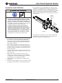
help immediately to remove oil. Figure 1
Piston
Support
Extended
Yoke
If any problems are found,do not use until problems have
been xed. Failure to follow these instructions increases
the risk of injury.
If using the extended yoke, inspect the ram and conrm
the piston support (Fig. 1) is installed. Do not bend with
the extended yoke if the piston support is not installed.
An unsupported ram can shift during bending resulting
in poor bends and damage to the tool that increases the
risk of parts breaking and causing injury.

Cam Track® Hydraulic Bender
52093598 Rev 0010 © 2022 Greenlee Tools, Inc.
Tool Set-Up* & Operation When the 881 bending is to be operated of the oor,
follow these steps for set up and operation. See Mobile
Bending Table for 881 Hydraulic Bender instruction
manual for MBT mounting and operation information.
1. Check work area for:
• Adequate lighting
• A clear, level, stable and dry place for all
equipment and space for the operator to work
comfortably and according to tool operating
instructions to reduce the risk of injury.
• A clearly marked or easily recognizable work
site to prevent people from coming into the area
while the tool is being used. Barriers or cones
around work sites are ways to do this.
2. Inspect the work to be done. Determine what shoe,
follow bar, and saddle are needed for the conduit
size and type. Not using the correct shoe, follow
bar and saddle produces poor quality bends and
increases the risk of tool damage and injury.
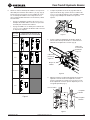
3. Conrm all related equipment has been inspected.
4. Attach the roller unit to the single prong ends of the
connecting forks, with decals and markings facing
out, and secure with the hitch pin clips. (Fig. 2)
• Do not stand in a direct line with the follow
bar, hydraulic ram or conduit while bending.
The bender is under high pressure during use
and has the potential to break and throw parts,
causing serious injury.
• Keep your fingers, hands, and other body
parts away from bender, attachments, conduit
and moving parts. Body parts can be struck,
crushed, fractured, or amputated if they become
caught between the attachment or between these
components and any other object.
• Do not bend Aluminum EMT. Conduit may
break causing serious injury.
• Some parts and accessories of this tool are
heavy. Use proper lifting techniques to reduce
the risk of injury.
• Use proper combination of accessories for the
specific conduit size. Bends will be incorrect
and injury or damage to the tool could result.
• Proper set up is essential to minimize risk
during use. Set up the tool and work area
according to these procedures to reduce the risk
of injury.
• One person must control the work process
and machine operation. Only the operator
should be in the work area when the machine is
operating. This helps reduce the risk of injury.
• Stay alert, watch what you are doing and use
common sense when operating the bender. Do
not use the bender while you are tired or under
the inuence of drugs, alcohol, or medication.
A moment of inattention while operating power
tools may result in serious personal injury.
• High pressure oil easily punctures skin,
causing serious injury, gangrene, or death. Do
not use hands to check for leaks. Stay away
from pressurized components. Depressurize
hydraulic system before touching the hose/
attachments. If injured, seek medical help
immediately to remove oil.
5. Position the cylinder block so the ram scale is
toward the oor then slide the ram in between the
connecting forks. (Fig. 3)
Figure 2
Figure 3
Scale
Floor

Cam Track® Hydraulic Bender
1152093598 Rev 00 © 2022 Greenlee Tools, Inc.
7. Pin the appropriate yoke to the ram piston with the
spring clip. (Fig. 5) To bend 3-1/2” and 4” conduit
after using the extended yoke, change to the yoke
and leave the cylinder block in the top position.
8. Insert the cylinder block hitch from the side where
the cylinder block extends out past the connecting
forks.(Fig. 6)
Figure 5
Figure 6
Hitch Pin
Clip Holes
Hitch
Pin
Head
Cylinder
Block
6. Line up the cylinder block holes with the appropriate
position for the conduit size and yoke. (Fig.4) Pay
attention to the marks on the connecting forks. If
the cylinder block is in the wrong position, the ram
could over extend and cause tool damage.
• The yoke is used for 2-1/2”- 4” conduit and the
cylinder block must be located at the position
marked for the conduit size.
• The extended yoke is only used for 2-1/2”and
3” conduit and the cylinder block must be
located at the top position.
Figure 4
Figure 7
9. While keeping the hitch pin head tight against the
connecting fork face, insert the clip in the hole
closest to the opposite connecting fork face. Repeat
for second pin. (Fig. 7)
CONDUIT
SIZE
CYLINDER BLOCK &
YOKE-SHOE CONNECTIONS
2-1/2”
3“
3-1/2”
4”
94848G
Forks
26309
Forks
For
Changeover

Cam Track® Hydraulic Bender
52093598 Rev 0012 © 2022 Greenlee Tools, Inc.
11. Arrange the shoe between the connecting forks so
the saddle connection is to the left. Align the yoke
with the EMT or IMC/Rigid connection on the shoe
depending on the type of conduit to be bent. Insert
yoke pin through the yoke and shoe until the toggles
fully expand on the other side. (Fig. 9)
12. With the ears turned toward the ram, insert the
“START” end of the follow bar from the right of the
connecting forks over the roller. (Fig. 10)
13. Once the “START” end is past the roller, turn the
follow bar so that the conduit groove is toward the
ram and the follow bar ears touch the ground. (Fig.
11)
For changeover to other shoe groups, remove cyl-
inder block hitch pin clips, as necessary, and insert
into outermost hole of hitch pin (Fig.7). Lift connect-
ing fork enough to allow the follow bar through.
Return the hitch pin clips to the appropriate holes
for bending. Do not bend without the hitch pin clips
installed, poor quality bends and tool damage could
occur.
14. Prepare the conduit by marking the bends following
the instructions in the Bending Basics section of this
manual.
15. Check the conduit, shoe and follow bar grooves
are clean. Debris on the bending surfaces increase
the risk of wrinkling or creasing of conduit and can
cause damage to the grooves in the shoe and follow
bar.
16. Insert the conduit into the bender. Push the conduit
through so the end is past the shoe at least a few
inches.
17. Arrange the saddle around the conduit at the front
of the shoe with the saddle lip facing away from the
follow bar. Insert the Saddle pin all the way through
the shoe and saddle holes until the toggles fully
expand.
18. Adjust the saddle and shoe so the back edge con-
tacts the follow bar. (Fig.12)
19. Adjust the conduit so the appropriate bending
mark is lined up with the saddle lip. See Basics of
Bending for further instructions on marking conduit.
Figure 10
Figure 11
Figure 12
Figure 9
IMC/Rigid
EMT
Saddle
Connection
Shoe Conduit
Size ID
Figure 8
Scale Hitch Pin
Clips
Cylinder
Block
Cylinder
Block
Follow Bar
Ears
Conduit
Groove
“START”
Conduit Size
Saddle Follow Bar
10. Turn the assembled bender onto the cylinder block
so the hitch pin clips and ram scale are facing up
(Fig. 8). The cylinder block is designed to level out
the bender cylinder while bending on the oor.

Cam Track® Hydraulic Bender
1352093598 Rev 00 © 2022 Greenlee Tools, Inc.
Figure 14
20. Place a Greenlee 900 series hydraulic pump next to
the bender on the oor so the front of the pump is
facing the operator.
21. Attach the free end of the hose from the ram to the
pump coupler, make sure the coupler is screwed
tight to ensure proper ram function. Incomplete con-
nections may not allow the ram to retract after the
bend is complete.
22. Assume a proper operating position where you are
not in the path of the conduit or ram and can clearly
see the bender scale and pump. (Fig,14)
23. Snug-up the conduit by advancing the ram accord-
ing to the pump instructions. The conduit is
snugged-up when the shoe, conduit, and follow bar
are tight. Stop the pump before the conduit starts to
bend.
24. Move the scale’s O-ring to Z-Position. See
Calculate Ram Travel section for equation and
tables.
25. Monitor the bending process. Advance the ram to
Z-position. The bend is complete when the O-ring
reaches the top of the cylinder block. Stay out of
the line of the conduit and ram while bender is in
motion.
26. When bend is complete, operate the pump, accord-
ing to its instructions to retract the ram to the start-
ing position for the next bend.
27. Remove the saddle pin, saddle and conduit from
bender. Compress the toggles and pull the Yoke and
Saddle pins out to disconnect accessories. (Fig. 15)
28. Inspect the nished bend.
Figure 15

Cam Track® Hydraulic Bender
52093598 Rev 0014 © 2022 Greenlee Tools, Inc.
1. Snug-up bender by advancing ram until shoe,
conduit, and follow bar are tight. The conduit should
not be able to twist between the saddle and shoe.
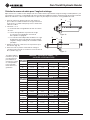
2. Calculate Z = X + Y
Z = Stop position on ram scale based on X and Y.
X = Scale reading at Snug-Up position.
Find X by looking where the scale and top of the
cylinder block meet.
Y = The Ram Travel from Table 1. This is how far the
ram should travel to achieve the desired bend
angle for a specic conduit size.
3. Move rubber ring to calculated Z-Position. (Fig. 16)
4. Advance ram to the Z-Position. Monitor the bend
and stop when the rubber ring touches the top of
the cylinder block. (Fig. 17)
TABLE 1 RAM TRAVEL* - "Y"
(VALUES ARE APPROXIMATE)
BEND
ANGLE
EMT (CONDUIT TRADE SIZE - in.)
2-1/2 3 3-1/2 4
10° 13/16 15/16 1 7/8
15° 1-1/16 1-5/16 1-3/8 1-3/8
30° 2 2-7/16 2-3/8 2-7/16
45° 2-15/16 3-11/16 3-3/8 3-5/8
60° 3-13/16 4-13/16 4-3/8 4-7/8
90° 5-5/16 6-13/16 6-11/16 7-1/4
BEND
ANGLE
IMC (CONDUIT TRADE SIZE - in.)
2-1/2 3 3-1/2 4
10° 1-1/8 1-3/16 1-1/16 1-3/16
15° 1-9/16 1-11/16 1-1/2 1-13/16
30° 2-7/8 3-1/4 3 3-3/16
45° 4-5/16 5 4-3/8 4-13/16
60° 5-13/16 6-3/4 5-13/16 6-7/16
90° 8-1/8 9-5/8 8-13/16 9-11/16
BEND
ANGLE
RIGID (CONDUIT TRADE SIZE - in.)
2-1/2 3 3-1/2 4
10° 1-1/16 1-3/16 1 1-1/16
15° 1-1/2 1-11/16 1-1/2 1-11/16
30° 2-7/8 3-5/16 2-7/8 3-3/16
45° 4-1/4 5 4-1/4 4-13/16
60° 5-5/8 6-11/16 5-3/4 6-7/16
90° 8-1/8 9-9/16 8-3/4 9-11/16
Figure 17
*This table shows
the distance (Y) the
ram must travel
to make a bend.
These numbers are
not the end posi-
tion located on the
scale.
Figure 16
Calculating Ram Travel for Bend Angle
After the conduit has been snugged up, the ram must travel a particular distance to achieve the desired bend angle
(Table 1). A rubber O-ring on the ram scale is used to indicate the position at which the bend angle is achieved. Use
the directions below to determine where to place the rubber O-ring on the ram scale.
XYZ
XYZ

Cam Track® Hydraulic Bender
1552093598 Rev 00 © 2022 Greenlee Tools, Inc.
The following drawings, instructions and bending tables are intended to provide the information necessary to set up
the most common types of bends. The “Special Bending Tables” at the back of this manual, contain precise mea-
surements used for nding the marks for most common bends. Some types of bends have their own tables that
provide numbers for nding the bending marks. Below are some of the most common terms used in bending.
Basics of Bending
Glossary
Leg Length—The distance from the
end of a horizontal section of conduit
or pipe to the bend; measured from
the end to the center line, inside edge,
or outside edge of the conduit or pipe.
Stub/Stub-Up/Rise— The distance
from the end of the vertical section of
conduit or pipe to the bend; mea-
sured from the end to the center line,
inside edge, or outside edge of the
conduit or pipe.
Springback—The amount, measured
in degrees, that a conduit or pipe
tends to straighten after pressure
is released on the bender ram. For
example, a 90° bend, after pressure is
released, will spring back about two
degrees – to 88°.
Center-to-Center Distance—the distance between the
successive bends that make up an offset or a three-
bend saddle.
O.D.—The size of any piece of
conduit or pipe as measured
by its outside diameter.
Snug-up - The process of securing the conduit between
the shoe and saddle by advancing the ram enough
to keep the conduit in place but not enough to start
bending.
Ram Travel - The distance that the ram of a hydraulic
bender must move to reach a specific bend angle.
Developed/Determined Length -The actual length of
the pipe that will be bent.
Min. Stub Length - A stub must be equal to or larger
than this number to avoid crushing threads and bad
quality bends.
Deduct - A calculated number to account for gain while
bending. This number is specific to the size and type of
conduit being bent.
Bend Angle/Angle of Bend - The target bend angle .
Kick - A bend, usually less than 45o, made to change
the direction of a section of pipe.
Center Line - The imaginary line running through the
center of the conduit.
Bend Radius - The radius as measured from where the
center of the bend is located. This is a xed number
based on the bending shoe.
Dog Leg Bend/Wow - A bend, usually no more than
45o, made to change the direction of a section of pipe
not on the same plane.
Large Sweep Bends - Any bend which exceeds the
radius of one-shot 90° bending shoes supplied with
one-shot hydraulic power benders.
Comeback - When making a 90° bend having a
definite leg length (or rise) the center of the bend must
be located when using certain benders. To do this, first
measure the leg length from the end of straight section
of pipe. Then, “come back” 1/2 the gain to locate the
center of the bend.
Degree indicator - This is an instrument designed
to indicate the exact degree of bend while it is being
made.
Protractor - Made for use with Benders mounted on
Bending Table. Measures degrees – also has scale
for 18°, 20°, 21° and 22° bends when using to make a
large sweep bend.
Segment Bend - Any bend formed by a series of
bends of a few degrees each, rather than a single one-
shot bend.
Gain - The difference between the right
angle distances A & B and the shorter
distance C. Because pipe bends in
a radius and not at right angles, the
length of pipe needed for a bend will
not equal the total determined length.
A
B
C
Height/Depth of Offset - The distance that the conduit
or pipe must be re-routed to avoid an obstruction.
A
H

Cam Track® Hydraulic Bender
52093598 Rev 0016 © 2022 Greenlee Tools, Inc.
Figure 22
Bending Marks
TABLE 2 —MIN. STUB HEIGHT, DEDUCT (IN.)
CONDUIT SIZE 2-1/2 3 3-1/2 4
EMT
DEDUCT 21-1/2 24 27-3/4 32-1/4
MIN. STUB LENGTH (H) 24 27 31-1/4 36-1/4
MIN. DISTANCE FROM END OF CONDUIT 2-1/2 3 3-1/2 4
IMC RIGID
DEDUCT 21-1/2 24-1/4 28-1/4 32-1/2
MIN. STUB LENGTH (H) 24 26-3/4 30-3/4 35
MIN. DISTANCE FROM END OF CONDUIT 2-1/2 2-1/2 2-1/2 2-1/2
Figure 21
1. In the appropriate Special Bending Table,use the
desired stub height (H) and angle to nd Y. (Fig.20)
2. Measure Y distance from the end of the conduit and
place the bending mark here. (Fig.21)
1. Make MARK 1 by measuring to the Target Stub
Length (H). (Fig.22)
2. Make MARK 2 by measuring the DEDUCT (Table
2) from MARK 1 towards the threads. (Fig.23) The
distance between MARK 2 to the end of the conduit
cannot be less than the MIN. STUB LENGTH.
Less than 90° Bend Marks
90° Bend Marks
Figure 20
HANGLE MARK
Y
Figure 23
TARGET
STUB
LENGTH
DEDUCT
MARK
2MARK
1
90o
H
Making a Bend
1. Set up the 881 Hydraulic Bender according to its
instructions in this manual and use accessories
specic to the conduit to be bent.
2. Observe work site and select the size and type of
conduit. The conduit determines what set of table
numbers are used for nding the bend marks.
3. Determine the Stub Height (H) and the Bend Angle.
(Fig.18) These numbers determine the appropriate
numbers needed from the bending tables. Different
types of bends use different tables and variables
follow the instructions for the type of bend to know
what variables are needed.
Figure 18
Figure 19
Bending
Mark
Saddle Lip
6. Snug-up bender. Advance the ram until the conduit
cannot shift but before the conduit is actually bent.
7. Calculate Z position (see Ram Travel) for desired
bend angle and move rubber ring on the ram scale
to mark.
8. Advance ram to Z-position.
9. Reverse ram until fully retracted to release the con-
duit. Remove conduit and check bend.
ANGLE
4. Mark the conduit by following the instruction for the
type of bend and using the appropriate tables. The
Special Bending Tables are used unless otherwise
specied.
5. Insert conduit between saddle and shoe. Line up
the appropriate bending mark with the saddle lip.
and make sure the follow bar is touching the back
of the saddle. (Fig.19)
TARGET
STUB
LENGTH(H)

Cam Track® Hydraulic Bender
1752093598 Rev 00 © 2022 Greenlee Tools, Inc.
Bending Marks
Offsets
An offset is made to avoid an obstruction blocking the run of the conduit. To make an offset, two equal bends are
required in opposite directions to create a rise that will go around the obstruction. Depending on the end position
desired, the mark positions are based off different numbers in the tables.
TABLE 3 "X" DISTANCE (in.)
CONDUIT SIZE 2-1/2 3 3-1/2 4
EMT
X6-5/32 5-3/4 6-9/16 8-1/2
MIN. DIST.
FROM END
OF CONDUIT 2-1/2 3 3-1/2 4
IMC/
RIGID
X6-5/32 6 7 8-3/4
MIN. DIST.
FROM END
OF CONDUIT 2-1/2 2-1/2 2-1/2 2-1/2
1. Select the size and type of conduit. Measure the
height (H) of the obstruction. Use the column with
an offset that will overcome the obstruction to, nd X
and A-Measurements.
2. Make MARK 1 by measuring the distance from end
of conduit to desired start of 1st bend.
3. Make MARK 2 on conduit by subtracting X (Table 3)
from MARK 1.
The distance from MARK 2 to the end of the conduit
cannot be less than the MIN. DIST. FROM END OF
Conduit to avoid crushing threads and bad quality
bends.
4. Find the “A” distance (Table 4). Make MARK 3 on the
conduit by measuring this distance from MARK 2.
5. Aline MARK 2 with outside edge of saddle for the
1ST Bend. Advance ram to calculated Z-Position for
desired angle.
6. Rotate conduit 180˚. Aline MARK 3 with outside edge
of the saddle for the second bend.
Center-to-Center Offset (Fig.24)
TABLE 4 "A" DISTANCE* (in.)
(VALUES ARE APPROXIMATE)
For offset distances not on this table, calculate “A” by
multiplying the appropriate multiplier (Table 5) to the desired OFFSET.
O
F
F
S
E
T
15° 30° 45°
MAX
COND.
SIZE AMAX
COND.
SIZE AMAX
COND.
SIZE A
23/4 7-3/4
41-1/2 15-7/16 3/4 8
63-1/2 23-3/16 1-1/2 12 1/2 8-1/2
84 30-15/16 2 16 1 11-5/16
10 4 38-5/8 3-1/2 20 1-1/4 14-1/8
12 4 46-3/8 4 24 1-1/2 16-15/16
14 4 54-1/16 4 28 2 19-13/16
16 4 61-13/16 4 32 2-1/2 22-5/8
18 4 69-9/16 4 36 3 25-7/16
20 4 77-1/4 4 40 3-1/2 28-1/4
22 4 85 4 44 4 31-1/8
Figure 24
2nd
BEND
H
ANGLE
1st
BEND
TABLE 5 “OFFSET”
MULTIPLIERS
BEND ANGLE MULTIPLIER
15° 3.86
30° 2
45° 1.4
* The “A” values on this table are the same for any conduit less
than the maximum. Values in gray are for reference only. The
881 Bender cannot bend conduit less than 2-1/2”.
A
MARK
1
MARK
3
MARK
2
X
LENGTH
TO 1st
BEND
CENTER
TO
CENTER

Cam Track® Hydraulic Bender
52093598 Rev 0018 © 2022 Greenlee Tools, Inc.
1. Find the Special Bending Table for the size and type
of conduit. In the table nd the row with the angle
of bend and the column with the height of stub de-
sired. Use the numbers from where these intersect
to nd bending marks
2. Subtract X from the LENGTH TO 1ST BEND to nd
the position of MARK 1.
3. Measure L1 from MARK 1 and place MARK 2 here.
4. Line up MARK 2 with outside edge of saddle for the
1st Bend.
5. Rotate conduit 180˚ and line up MARK 1 with out-
side edge of the saddle for the 2nd Bend.
1. Find the Special Bending Table for the size and type
of conduit. In the table nd the row with the angle
of bend and the column with the height of stub de-
sired. Use the numbers from where these intersect
to nd bending marks
2. Subtract Z from LENGTH TO 2ND BEND to nd the
position of MARK 2.
3. Measure L1 from MARK 2 and place MARK 1 here.
4. Line up MARK 2 with outside edge of saddle for the
1st Bend.
5. Rotate conduit 180˚ and line up MARK 1 with out-
side edge of the saddle for the 2nd Bend.
When working past an obstruction, it is necessary to determine the location of the 1st Bend (MARK 1). The center-
to-center distance is then used to nd the location of the
2nd Bend (MARK 2).
Offset-Working Past an Obstruction (Fig.25)
When working toward an obstruction, it is necessary to determine the location of the 2nd Bend. The center-to-
center distance is then used to nd the location of the 1st Bend.
Offset-Working Toward an Obstruction (Fig.26)
1. Select the size and type of conduit. Find the chart
that corresponds to the size and type of conduit se-
lected in the Special Bending Tables.
2. Determine the HEIGHT and the LENGTH of the stub.
Select the angle for the bend.
3. Follow the 90° ANGLE row and the HEIGHT column
for the desired bend. Use the Y and L1 dimensions
from that box.
4. Locate MARK 1 Y distance end of conduit/threads.
5. Add L1 to MARK 1 to nd the position of MARK 2.
6. Line up MARK 1 with the outside edge of the saddle.
Bend 90°.
7. Line up MARK 2, keeping the conduit in the same
orientation. Bend 90°.
Back-to-Back or U-Bend (Fig.27)
A U-shaped bend formed by two parallel 90-degree bends with a straight section of conduit or pipe between the
bends
Figure 25
Figure 26
Figure 27
2nd
BEND
MARK
1
ANGLE
1st
BEND
MARK
2
LENGTH - X
L1
H
LENGTH - Z
MARK
1
MARK
2
L1
LENGTH
2nd
BEND
ANGLE
LENGTH
H
Length
L1
Y
MARK
1MARK
2
90o
90o
H
LENGTH

Cam Track® Hydraulic Bender
1952093598 Rev 00 © 2022 Greenlee Tools, Inc.
Four-Bend Saddle (Fig.28)
1. Select the size and type of conduit. Find the chart
that corresponds to the size and type of conduit se-
lected in the Special Bending Tables.
2. Measure the HEIGHT of the obstruction and the
LENGTH TO 2ND BEND to the obstruction and the
STRAIGHT SECTION over the obstruction. Select
the angle for all bends.
3. Follow the ANGLE row to the HEIGHT column for the
desired bend. Use the Z, L1 and L2 dimensions.
4. Subtract Z from the Length to Center and measure
this distance from end of conduit/threads to nd
MARK 1. Measure L1 distance from MARK 1 to nd
MARK 2.
5. Measure L1 distance from MARK 1 to nd MARK 2.
6. Add L2 to the Straight Section length and measure
this distance from MARK 2 to nd MARK 3.
7. Line up MARK 1 with the outside edge of the saddle.
Bend to the selected angle.
8. Turn conduit 180° and line up MARK 2. Bend to the
selected angle.
9. Line up MARK 3, keeping the conduit in the same
orientation. Bend to the selected angle.
10. Turn conduit 180° and line up MARK 4. Bend to the
elected angle.
1. Select the size and type of conduit. Find the chart
that corresponds to the size and type of conduit se-
lected in the Special Bending Tables.
2. Measure the HEIGHT of the obstruction and the
LENGTH TO CENTER of the saddle. Select an angle
for the outer bends. The center bend will be twice
the selected angle. (i.e. 22-1/2° x 45° x 22-1/2°)
3. Follow the ANGLE row to the HEIGHT column for the
desired bend. Use the Z, L1 and L2 dimensions.
4. Subtract Z from the Length to Center and measure
this distance from end of conduit/threads to nd
MARK 1.
5. Measure L1 distance from MARK 1 to nd MARK 2.
6. Measure L2 distance from MARK 2 to nd MARK 3
7. Line up MARK 1 with the outside edge of the saddle
for the 1st bend. Bend to the selected angle.
8. Turn conduit 180° and line up MARK 2. Bend to twice
the selected angle.
9. Turn conduit again 180° and line up MARK 3. Bend to
the selected angle.
Three-Bend Saddle (Fig.27)
A Saddle creates a bridge to avoid an obstruction blocking the run of the conduit and returning the end of the con-
duit to the same level as the original run of conduit. They can be made using three or four bends
Saddle Bends
Figure 28
Figure 27
MARK
3
LENGTH
TO
CENTER
ANGLE
LENGTH - Z
L1 L2
2X
ANGLE
MARK
1MARK
2
H
LENGTH TO
2nd BEND
ANGLE
STRAIGHT
SECTION
MARK
3
LENGTH - Z
L1
MARK
1MARK
2MARK
4
L2 + STRIGHT SECTION
L1
H
ANGLE

Cam Track® Hydraulic Bender
52093598 Rev 0020 © 2022 Greenlee Tools, Inc.
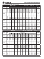
Special Bending Tables (in.)
2-1/2" EMT Dia. = 2.875 Radius = 13.9 x = 6.15
ANGLE DIM.HEIGHT (H)
MINIMUM
H
10" 12" 15" 18" 24" 30" 36" 42" 48" 60"
15°
Y25.10 32.83 44.42 56.01 79.19 102.38 125.56 148.74 171.92 218.29
2.54
L1 38.62 46.34 57.93 69.53 92.71 115.89 139.07 162.25 185.44 231.80
L2 42.26 49.98 61.57 73.16 96.35 119.53 142.71 165.89 189.08 235.44
Z47.13 54.59 65.79 76.99 99.38 121.77 144.16 166.56 188.95 233.73
22.5°
Y13.46 18.69 26.53 34.37 50.04 65.72 81.40 97.08 112.76 144.12
4.47
L1 26.06 31.29 39.13 46.97 62.64 78.32 94.00 109.68 125.36 156.72
L2 31.52 36.74 44.58 52.42 68.10 83.78 99.46 115.14 130.82 162.17
Z35.82 40.65 47.89 55.14 69.62 84.11 98.59 113.08 127.56 156.53
30°
Y7.25 11.25 17.25 23.25 35.25 47.25 59.25 71.25 83.25 107.25
6.80
L1 19.83 23.83 29.83 35.83 47.83 59.83 71.83 83.83 95.83 119.83
L2 27.11 31.11 37.11 43.11 55.11 67.11 79.11 91.11 103.11 127.11
Z30.92 34.38 39.58 44.78 55.17 65.56 75.95 86.35 96.74 117.52
45°
Y3.03 7.27 11.52 20.00 28.49 36.97 45.46 53.94 70.91
12.49
L1 16.37 20.62 24.86 33.34 41.83 50.31 58.80 67.28 84.25
L2 27.29 31.53 35.77 44.26 52.75 61.23 69.72 78.20 95.17
Z29.67 32.67 35.67 41.67 47.67 53.67 56.67 65.67 77.67
60°
Y1.49 4.95 11.88 18.81 25.73 32.66 39.59 53.45
19.23
L1 26.22 33.15 40.07 47.00 53.93 67.79
L2 40.77 47.70 54.63 61.56 68.49 82.34
Z36.06 39.52 42.98 46.45 49.91 56.84
90°
Y2.51 8.51 14.51 20.51 26.51 38.51
33.95
L1 30.03 36.03 42.03 54.03
L2 51.87 57.87 63.87 75.87
Z33.95 33.95 33.95 33.95
3" EMT Dia. = 3.5 Radius = 16.48 x = 5.77
ANGLE DIM.HEIGHT (H)
MINIMUM
H
10" 12" 15" 18" 24" 30" 36" 42" 48" 60"
15°
Y23.94 31.66 43.25 54.85 78.03 101.21 124.39 147.57 170.76 217.12
2.62
L1 38.61 46.34 57.93 69.52 92.70 115.89 139.07 162.25 185.43 231.80
L2 42.93 50.65 62.25 73.84 97.02 120.20 143.38 166.57 189.75 236.11
Z47.43 54.89 66.09 77.29 99.68 122.07 144.46 166.86 189.25 234.03
22.5°
Y12.51 17.74 25.58 33.42 49.09 64.77 80.45 96.13 111.81 143.17
4.72
L1 26.05 31.27 39.11 46.95 62.63 78.31 93.99 109.67 125.35 156.70
L2 32.52 37.74 45.58 53.42 69.10 84.78 100.46 116.14 131.82 163.17
Z36.47 41.30 48.54 55.78 70.27 84.75 99.24 113.72 128.21 157.18
30°
Y6.31 10.31 16.31 22.31 34.31 46.31 58.31 70.31 82.31 106.31
7.30
L1 19.80 23.80 29.80 35.80 47.80 59.80 71.80 83.80 95.80 119.80
L2 28.43 32.43 38.43 44.43 56.43 68.43 80.43 92.43 104.43 128.43
Z31.92 35.39 40.58 45.78 56.17 66.56 76.96 87.35 97.74 118.52
45°
Y1.90 6.14 10.38 18.87 27.36 35.84 44.33 52.81 69.78
13.73
L1 20.50 24.75 33.23 41.72 50.20 58.69 67.17 84.14
L2 33.45 37.69 46.18 54.66 63.15 71.63 80.12 97.09
Z34.42 37.42 43.42 49.42 55.42 61.42 67.42 79.42
60°
Y0.02 3.48 10.41 17.34 24.26 31.19 38.12 51.98
21.48
L1 25.94 32.87 39.80 46.73 53.65 67.51
L2 43.20 50.13 57.06 63.98 70.91 84.77
Z38.66 42.12 45.58 49.05 52.51 59.44
90°
Y0.00 6.00 12.00 18.00 24.00 36.00
38.73
L1 34.93 40.93 52.93
L2 60.81 66.81 78.81
Z38.73 38.73 38.73
La page est en cours de chargement...
La page est en cours de chargement...
La page est en cours de chargement...
La page est en cours de chargement...
La page est en cours de chargement...
La page est en cours de chargement...
La page est en cours de chargement...
La page est en cours de chargement...
La page est en cours de chargement...
La page est en cours de chargement...
La page est en cours de chargement...
La page est en cours de chargement...
La page est en cours de chargement...
La page est en cours de chargement...
La page est en cours de chargement...
La page est en cours de chargement...
La page est en cours de chargement...
La page est en cours de chargement...
La page est en cours de chargement...
La page est en cours de chargement...
La page est en cours de chargement...
La page est en cours de chargement...
La page est en cours de chargement...
La page est en cours de chargement...
La page est en cours de chargement...
La page est en cours de chargement...
La page est en cours de chargement...
La page est en cours de chargement...
La page est en cours de chargement...
La page est en cours de chargement...
La page est en cours de chargement...
La page est en cours de chargement...
La page est en cours de chargement...
La page est en cours de chargement...
La page est en cours de chargement...
La page est en cours de chargement...
La page est en cours de chargement...
La page est en cours de chargement...
La page est en cours de chargement...
La page est en cours de chargement...
La page est en cours de chargement...
La page est en cours de chargement...
La page est en cours de chargement...
La page est en cours de chargement...
La page est en cours de chargement...
La page est en cours de chargement...
La page est en cours de chargement...
La page est en cours de chargement...
La page est en cours de chargement...
La page est en cours de chargement...
La page est en cours de chargement...
La page est en cours de chargement...
La page est en cours de chargement...
La page est en cours de chargement...
La page est en cours de chargement...
La page est en cours de chargement...
La page est en cours de chargement...
La page est en cours de chargement...
-
 1
1
-
 2
2
-
 3
3
-
 4
4
-
 5
5
-
 6
6
-
 7
7
-
 8
8
-
 9
9
-
 10
10
-
 11
11
-
 12
12
-
 13
13
-
 14
14
-
 15
15
-
 16
16
-
 17
17
-
 18
18
-
 19
19
-
 20
20
-
 21
21
-
 22
22
-
 23
23
-
 24
24
-
 25
25
-
 26
26
-
 27
27
-
 28
28
-
 29
29
-
 30
30
-
 31
31
-
 32
32
-
 33
33
-
 34
34
-
 35
35
-
 36
36
-
 37
37
-
 38
38
-
 39
39
-
 40
40
-
 41
41
-
 42
42
-
 43
43
-
 44
44
-
 45
45
-
 46
46
-
 47
47
-
 48
48
-
 49
49
-
 50
50
-
 51
51
-
 52
52
-
 53
53
-
 54
54
-
 55
55
-
 56
56
-
 57
57
-
 58
58
-
 59
59
-
 60
60
-
 61
61
-
 62
62
-
 63
63
-
 64
64
-
 65
65
-
 66
66
-
 67
67
-
 68
68
-
 69
69
-
 70
70
-
 71
71
-
 72
72
-
 73
73
-
 74
74
-
 75
75
-
 76
76
-
 77
77
-
 78
78


Greenlee 52093598 REV 0 Manuel utilisateur
- Taper
- Manuel utilisateur
dans d''autres langues
Documents connexes
-
Greenlee 881 & 881CT Cam Trak Hydraulic Bender Manuel utilisateur
-
-
-
-
-
-
-
-
-