Greenlee 1818 Mechanical Bender - Serial No. YY and up Manuel utilisateur
- Taper
- Manuel utilisateur

99901404 © 2012 Greenlee Textron Inc. IM 1101 REV 16 5/12
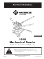
1818
Mechanical Bender
For all benders with Serial No. Code YY-0000 and up
INSTRUCTION MANUAL
Read and understand all of the instructions and
safety information in this manual before operating
or servicing this tool.
Register this product at www.greenlee.com
Français .............. 19

Greenlee / A Textron Company 2 4455BoeingDr.•Rockford,IL61109-2988USA•815-397-7070
1818 Mechanical Bender
Allspecicationsarenominalandmaychangeasdesignimprove-
ments occur. Greenlee Textron Inc. shall not be liable for damages
resulting from misapplication or misuse of its products.
KEEP THIS MANUAL
Table of Contents
Description ..................................................................... 2
Safety ............................................................................. 2
Purpose of this Manual .................................................. 2
ImportantSafetyInformation ......................................... 3
Instructions for Bending ..............................................4-8
SpecialBendingInformation .....................................9-11
SpecialBendingInformationCharts .......................12-17
French .....................................................................19-35
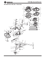
Illustration ..................................................................... 37
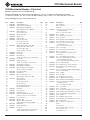
PartsList ...................................................................... 38
Description
Capacity
3/4"–2"EMT
1/2"–1-1/4"IMC
1/2"–1-1/2"GalvanizedRigidConduit
2"Aluminum(only)RigidConduit
Note: Radius of bend is clearly marked on each
bending shoe.
The1818MechanicalBenderisdesignedforyearsof
dependabletrouble-freeservice.
Thesefeaturesmakethe1818benderoneofthemost
versatiletimesavingtoolsonthemarket.
• Built-InRatchet—letsyouapplyshort,powerful
strokesforfasterbending.
• ShoeLocator—makesloadingeasy.Shoerotationis
restricted.
• BendingDegreeIndicator—helpsassureaccurate
bends every time.
• FollowBars—producesmoothbendsin1-1/4",
1-1/2"and2"EMTwithoutkinksorwrinkles.
• RubberWheels—provideeasyportabilityintheshop
or on the jobsite.
• StrongFrame—keepsbenderinplaceduring
bending.
• Speed-bendMode—bypassesratchetforfast,direct
bendingofsmallersizesofconduit.
Features that make the 1818 superior
• Nostorageboxrequired.Alloftheshoesmaybe
stored on the bender.
Note: Bender holds follow bars, rollers and pins so the
complete unit may be chained to a post for security.
• Thecarriageminimizesdeectionwhenbendinglarger
conduit.
• Thesteelmainframedoesnotrequireatiebartosup-
port the bending system.
• Theshoeandratchetsegmentunitisautomatically
retainedbythefrictionbuttonwhenloadingthecon-
duit.Thelocksystemreleasesautomatically.
• Theframeunitacceptsexisting1818shoes,cushion
rollerandfollowbars.
Safety
Safetyisessentialintheuseandmaintenanceof
Greenleetoolsandequipment.Thisinstructionmanual
andanymarkingsonthetoolprovideinformationfor
avoidinghazardsandunsafepracticesrelatedtothe
use of this tool. Observe all of the safety information
provided.
Purpose of this Manual
Thisinstructionmanualisintendedtofamiliarizeperson-
nelwiththesafeoperationandmaintenanceprocedures
fortheGreenlee1818MechanicalBender.
Keep this manual available to all personnel.
Replacementmanualsareavailableuponrequest
atnochargeatwww.greenlee.com.

Greenlee / A Textron Company 3 4455BoeingDr.•Rockford,IL61109-2988USA•815-397-7070
1818 Mechanical Bender
IMPORTANT SAFETY INFORMATION
SAFETY
ALERT
SYMBOL
Thissymbolisusedtocallyourattentiontohazards
orunsafepracticeswhichcouldresultinaninjuryor
propertydamage.Thesignalword,denedbelow,
indicatestheseverityofthehazard.Themessage
afterthesignalwordprovidesinformationfor
preventingoravoidingthehazard.
Immediatehazardswhich,ifnotavoided,WILLresult
in severe injury or death.
Hazardswhich,ifnotavoided,COULDresultin
severe injury or death.
Hazardsorunsafepracticeswhich,ifnotavoided,
MAYresultininjuryorpropertydamage.
Read and understand all of the
instructions and safety information
in this manual before operating or
servicing this tool.
Failuretoobservethiswarningcould
result in severe injury or death.
Do not leave the ratchet handle in the
UPpositionwhenthebenderisnotin
use.AhandleleftintheUPposition
could fall unexpectedly.
Pinch points:
Keephandsawayfrommovingparts
andconduitwhenbending.Failureto
observethiswarningcouldresultin
severe injury.
Weareyeprotectionwhenusingthis
bender.Failuretoweareyeprotection
could result in serious eye injury from
yingdebris.
• Keeptheconduitundercontrolwhenunloadingit
fromthebender.Conduitmayfallandstrikethe
operator or nearby personnel.
• Maintainarmgriponthehandlewhenbend-
ing.Springbackoftheconduitmaynotallowthe
ratchettofullyengage,causingthehandletospring
upwardsuddenly.
• Removethehandleandconduitbeforemovingthe
bender.Maintainarmgripwithbothhandsonthe
frameT-handletopreventthebenderfromtipping
over.
• Inspectthebenderbeforeeachuse.Replaceany
worn,damaged,ormissingitemswithGreen-
leereplacementparts.Adamagedorimproperly
assembledtoolcanbreakandstrikenearbyper-
sonnel.
• Useproperliftingpracticeswhenliftingthebender.
Thebenderweighsover75lb(34kg),andrequires
more than one person to lift.
Failure to observe these precautions may result
in injury.
Usethisproductforthemanufacturer’sintended
purposeonly.Useotherthanthatwhichisdescribed
in this manual may result in injury or property
damage.

Greenlee / A Textron Company 4 4455BoeingDr.•Rockford,IL61109-2988USA•815-397-7070
1818 Mechanical Bender
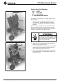
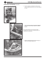
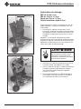
Instructions for Bending:
3/4" – 1" EMT
1/2" – 1-1/4" IMC
1/2" – 1-1/2" Rigid
2" Rigid Aluminum Conduit
Forhandleuse5'lengthof1-1/4"rigidconduit;retain
withsetscrew.
1. Rotatetheratchetsegmentcounterclockwiseto
LOADposition.Thefrictionbuttonwillpopout
and retain the segment from rotating in the bend
direction.
Note: The ratchet handle must be rotated to the UP
position to release the lock and drive pawls from the
segment. The segment may require a small amount of
clockwise rotation to release the lock pawl.
Do not leave the ratchet handle in the
UPpositionwhenthebenderisnotin
use.AhandleleftintheUPposition
could fall unexpectedly.
2. Selectthecorrectbendingshoe(sizeandtypeof
conduitismarkedontheshoe).
3. Placethebendingshoeonthepivotshaftandalign
thedrivepinonthesegmentwiththeholeinthe
shoe.Snapspringcliponpivotshaft.
4. Place the cushion roller on the roller pin and insert
intotheproperhole,asindicatedbythedecalon
the bender frame.
3
4
2
1
Handle in
UPPosition

Greenlee / A Textron Company 5 4455BoeingDr.•Rockford,IL61109-2988USA•815-397-7070
1818 Mechanical Bender
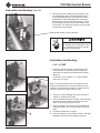
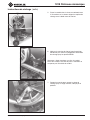
5. Placetheconduitinthebenderasshownonthe
shoeandalignbendingmarkswiththefrontedgeof
thehook.
Note: Set the pointer on zero, with the conduit
snug against the shoe hook. The indicator does not
compensate for spring-back.
7. Ratchetthebendingshoetothedesiredangle,as
shownbythedegreeanglepointer.
6. Lowertheratchethandletothehorizontalposition,
thenrotatethebendcontrolhandletotheBEND
position.
Instructions for Bending (cont’d)
5
6
POINTER

Greenlee / A Textron Company 6 4455BoeingDr.•Rockford,IL61109-2988USA•815-397-7070
1818 Mechanical Bender
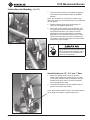
8. RotatetheratchethandletotheUPposition.This
willautomaticallymovethebendcontrolhandle
totheRELEASEposition.Thenrotatetheratchet
handledowntothebendingposition,andapply
bendpressureuntilthelockpawlreleases.Aclick
willbemade,thenrotatetheratchethandletothe
UPposition.Theshoeandsegmentmayberotated
to remove the bent conduit.
Bend control handle in release position.
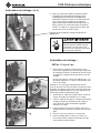
Instructions for Bending:
1-1/4"– 2" EMT
1. Rotatetheratchetsegmentcounterclockwiseto
LOADposition.Thefrictionbuttonwillpopout
and retain the segment from rotating in the bend
direction.
Forhandle,use5'lengthof1-1/4"rigidconduit;
retainwithsetscrew.
Note: The ratchet handle must be rotated to the UP
position to release the lock and drive pawls from the
segment. The segment may require a small amount of
clockwise rotation to release the lock pawl.
2. Selectthecorrectbendingshoe(sizeandtypeof
conduitismarkedontheshoe).
3. Placethebendingshoeonthepivotshaftandalign
thedrivepinonthesegmentwiththeholeinthe
shoe.Snapspringcliponpivotshaft.
4. Placesteelrollerinlinewiththeforwardholeand
outboard support. Insert the roller pin to retain the
roller.
5. Positionthefollowbarasshown.
6. Placetheconduitinthebenderasshown,andalign
bendingmarkwiththefrontedgeofthehook.
Instructions for Bending (cont’d)
5
3
1
Do not leave the ratchet handle in the
UPpositionwhenthebenderisnotin
use.AhandleleftintheUPposition
could fall unexpectedly.

Greenlee / A Textron Company 7 4455BoeingDr.•Rockford,IL61109-2988USA•815-397-7070
1818 Mechanical Bender
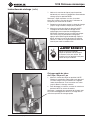
7. Lowertheratchethandletothehorizontalposition,
thenrotatethebendcontrolhandletotheBEND
position.
Note: Set the pointer on zero with the conduit snug
against the shoe hook. The indicator does not compensate
for spring-back.
8. Ratchetthebendshoetothedesiredangleas
shownbythedegreeanglepointer.
9. RotatetheratchethandletotheUPposition.This
willautomaticallymovethebendcontrolhandleto
theRELEASEposition.Thenrotatetheratchet
handledowntothebendingposition,andapply
bendpressureuntilthelockpawlreleases.Aclick
willbemade,thenrotatetheratchethandletothe
UPposition.Theshoeandsegmentmayberotated
to remove the bent conduit.
Do not leave the ratchet handle in the
UPpositionwhenthebenderisnotin
use.AhandleleftintheUPposition
could fall unexpectedly.
Speed Bending on 1/2", 3/4" and 1" Sizes
1. RotatetheratchethandletotheUPposition.
Removethehandleafterlooseningthesetscrew
in the ratchet handle. Place the handle on the post
locatedonthepivotshaft.Pulldownthehandle
untilrequiredbendismade.
2. Tounloadthebender,rotatethehandletotheUP
position and remove the conduit.
Note: Bend release handle will be in the release position
for bending with handle in speed bend location.
Instructions for Bending (cont’d)
1
7
9

Greenlee / A Textron Company 8 4455BoeingDr.•Rockford,IL61109-2988USA•815-397-7070
1818 Mechanical Bender
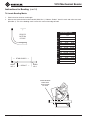
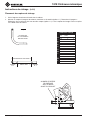
To Locate Bending Marks
1. Checkchartforminimumstublength.
2. Measureandmarkdesiredstubonconduit(MarkNo.1).Subtract“Deduct”fromthismarkandmakenewmark
(MarkNo.2).Thisisthebendingmark.Locatethismarkatfrontedgeofhook.
Instructions for Bending (cont’d)
BENDING CHART
R
I
G
I
D
E
M
T
I
M
C
Minimum
Conduit Stub Deduct
Size Length
1/2 7 6
3/4 9-1/8 8-1/8
1 11-1/4 10-1/4
1-1/4 13-7/8 12-3/8
1-1/2 16-3/4 15
2* 18-5/16 16-5/16
3/4 9-11/16 8-11/16
1 11-1/4 10-1/4
1-1/4 14-1/8 12-5/8
1-1/2 14-11/16 12-15/16
2 17 15
1/2 6-5/8 5-5/8
3/4 9-1/8 8-1/8
1 11-1/4 10-1/4
1-1/4 14 12-1/2
*
ALUMINUMONLY
FIGURESAREAPPROXIMATE
← STUB LENGTH →
← DEDUCT →
MARK
NO. 2
← →
MARK
NO. 1
STUB TO
BOTTOM
OF PIPE
A
LIGN BENDING
MARK WITH
FRONT EDGE
OF HOOK

Greenlee / A Textron Company 9 4455BoeingDr.•Rockford,IL61109-2988USA•815-397-7070
1818 Mechanical Bender
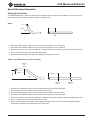
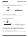
Setting Up Your Bends
Thefollowingdescribesameansforlayingoutthestartingpointsforvarioustypesofbends.Itwillgiveveryaccu-
rate measurements for heights and bend angles commonly used.
Stubs:
1. Gotothefollowingchartwhichisforthesizeandtypeofconduityouaretobend.
2. LookdowntotheANGLEcolumnuntilyoucometotheangleyouwanttobendto.
3. LookatthenumbersintherowprecededbyYandpicktheonethatisdirectlyundertheheight(H)youwant.
4. Placeamarkthisdistancefromtheendoftheconduit.
5. Makeyourbendafterpositioningthefrontedgeofthehookonyourmark.
Offsets: (Controlling the start of the first bend)
1. SubtracttheXdimensionforthesizeofconduittobebentfromthedesiredlength.
2. Placeyourrstmarkthisdistancefromtheendoftheconduit.
3. Gotothefollowingchartwhichisforthesizeandtypeofconduityouaretobend.
4. LookdowntotheANGLEcolumnuntilyoucometotheanglesyouwanttobendto.
5. LookatthenumbersintherowprecededbyL1andpicktheonethatisdirectlyundertheheight(H)youwant.
6. Placeasecondmarkthisdistancefromyourrstmark.
7. Makeyourrstbendafterplacingthefrontedgeofthehookontherstmarkandyoursecondbendafter
placingthefrontedgeofthehookunderthesecondmark.
Special Bending Information
← Y →
←
HEIGHT
ANGLE
MARK
←
←
←
←
←
L1
→
←
LENGTH – X
→
←
HEIGHT
→
←
LENGTH
→
START OF
FIRST
BEND
ANGLE
BENDING
MARK 1
BENDING
MARK 2
→
→

Greenlee / A Textron Company 10 4455BoeingDr.•Rockford,IL61109-2988USA•815-397-7070
1818 Mechanical Bender
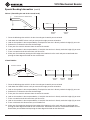
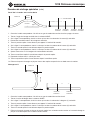
Special Bending Information (cont’d)
Offsets: (Controlling the end of the second bend)
1. Gotothefollowingchartwhichisforthesizeandtypeofconduityouaretobend.
2. LookdowntheANGLEcolumnuntilyoucometotheangleyouwanttobendto.
3. LookatthenumbersintherowprecededbyZandpicktheonethatisdirectlyundertheheight(H)youwant.
4. SubtractthisZdimensionfromthedesiredlength.
5. Placeyourrstmarkthisdistancefromtheendoftheconduit.
6. LookatthenumbersintherowprecededbyL1andpicktheonethatisdirectlyundertheheight(H)youwant.
7. Placeasecondmarkthisdistancefromyourrstmark.
8. Makeyourrstbendafterplacingthefrontedgeofthehookontherstmarkandyoursecondbendafter
placingthefrontedgeofthehookonthesecondmark.
3 Bend Saddles:
1. Gotothefollowingchartwhichisforthesizeandtypeofconduityouaretobend.
2. LookdowntheANGLEcolumnuntilyoucometotheangleyouwanttobendto.
3. LookatthenumbersintherowprecededbyZandpicktheonethatisdirectlyundertheheight(H)youwant.
4. SubtractthisZdimensionfromthedesiredlength.
5. Placeyourrstmarkthisdistancefromtheendoftheconduit.
6. LookatthenumbersintherowprecededbyL1andpicktheonethatisdirectlyundertheheight(H)youwant.
7. Placeasecondmarkthisdistancefromyourrstmark.
8. LookatthenumbersintherowprecededbyL2andpicktheonethatisdirectlyundertheheight(H)youwant.
9. Placeathirdmarkthisdistancefromyoursecondmark.
10. Makeyourrstbendafterplacingthefrontedgeofthehookontherstmarkandyoursecondbendafter
placingthefrontedgeofthehookonthesecondmark.Remembertomakethesecondbenddoubletherst
bend.Makeyourthirdbendafterplacingthefrontedgeofthehookonthethirdmark.
←
L1
→
←
LENGTH – Z
→
←
HEIGHT
→
←
LENGTH TO END OF SECOND BEND
→
ANGLE
BENDING
MARK 1
BENDING
MARK 2
→
→
←
L1
→
←
LENGTH – Z
→
← →
←
LENGTH TO CENTER
→
ANGLE
BENDING
MARK 1
BENDING
MARK 2
→
→
BENDING
MARK 3
←
L2
→
HEIGHT

Greenlee / A Textron Company 11 4455BoeingDr.•Rockford,IL61109-2988USA•815-397-7070
1818 Mechanical Bender
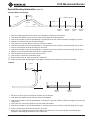
← L1 →
← Y →
←
HEIGHT
→
BENDING
MARK 1
BENDING
MARK 2
← LENGTH →
Special Bending Information (cont’d)
4 Bend Saddles with Straight
1. Gotothechartforthesizeandtypeofconduityouaretobend.
2. LookdowntheANGLEcolumnuntilyoucometo90degrees.
3. LookatthenumbersintherowprecededbyYandpicktheonethatisdirectlyunderthelength(L)youwantthe
length to be.
4. Placeyourrstmarkatthisdistancefromtheendoftheconduit.
5. LookatthenumbersintherowprecededbyL1andpicktheonethatisdirectlyundertheheight(H)youwant.
6. Placeasecondmarkthisdistancefromyourrstmark.
7. Makeyourrstbendafterplacingthefrontedgeofthehookontherstmarkandyoursecondbendafter
placingthefrontedgeofthehookonthesecondmark.
1. Gotothefollowingchartwhichisforthesizeandtypeofconduityouaretobend.
2. LookdowntheANGLEcolumnuntilyoucometotheangleyouwanttobendto.
3. LookatthenumbersintherowprecededbyZandpicktheonethatisdirectlyundertheheight(H)youwant.
4. SubtractthisZdimensionfromthedesiredlength.
5. Placeyourrstmarkthisdistancefromtheendoftheconduit.
6. LookatthenumbersintherowprecededbyL1andpicktheonethatisdirectlyundertheheight(H)youwant.
7. Placeasecondmarkthisdistancefromyourrstmark.
8. LookatthenumbersintherowprecededbyL2andpicktheonethatisdirectlyundertheheight(H)youwant.
9. AddthisL2valuetothedesiredlengthofyourstraightsection.
10. Placeathirdmarkthisdistancefromyourrstmark.
11. LookuptheL1dimensionusedaboveagain.
12. Placeafourthmarkthisdistancefromyourthirdmark.
13. Makeyourfourbendsbyplacingthefrontedgeofthehookontherespectivemarksforeachbend.
U-Bends
← L1 →
←
LENGTH – Z
→
← →
← LENGTH →
BENDING
MARK 1
BENDING
MARK 2
BENDING
MARK 3
←L2 + STRAIGHT SECTION →
HEIGHT
ANGLE
→
→
STRAIGHT
SECTION
←
←
L1 →
BENDING
MARK 4

Greenlee / A Textron Company 12 4455BoeingDr.•Rockford,IL61109-2988USA•815-397-7070
1818 Mechanical Bender
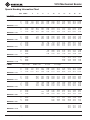
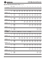
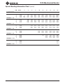
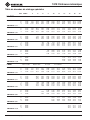
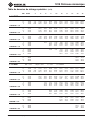
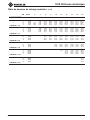
Special Bending Information Chart
DIM ANGLE 2" 4" 6" 8" 10" 12" 15" 18" 24" 36"
3/4 EMT Dia.=.922 Radius=5.25 X=2.98 H=Height
Y 15.00 2.28 10.00 17.73 25.46 33.18 40.91 52.50 64.09 87.28 133.64
L1 15.00 7.72 15.45 23.17 30.90 38.63 46.36 57.95 69.54 92.72 139.09
L2 15.00 9.09 16.82 24.55 32.28 40.00 47.73 59.32 70.91 94.10 140.46
Z 15.00 11.83 19.29 26.75 34.22 41.68 49.15 60.34 71.54 93.93 138.72
MINIMUM H = 1.13
Y 22.50 5.22 10.45 15.68 20.90 26.13 33.97 41.81 57.49 88.84
L1 22.50 5.20 10.43 15.65 20.88 26.10 31.33 39.17 47.01 62.69 94.05
L2 22.50 7.26 12.49 17.71 22.94 28.17 33.39 41.23 49.07 64.75 96.11
Z 22.50 9.90 14.73 19.55 24.38 29.21 34.04 41.28 48.52 63.01 91.98
MINIMUM H = 1.94
Y 30.00 2.69 6.69 10.69 14.69 18.69 24.69 30.69 42.69 66.69
L1 30.00 7.94 11.94 15.94 19.94 23.94 29.94 35.94 47.94 71.94
L2 30.00 10.68 14.68 18.68 22.68 26.68 32.68 38.68 50.68 74.68
Z 30.00 12.72 16.19 19.65 23.11 26.58 31.77 36.97 47.36 68.15
MINIMUM H = 2.90
Y 45.00 2.68 5.51 8.34 11.16 15.41 19.65 28.13 45.11
L1 45.00 8.26 11.09 13.92 16.74 20.99 25.23 33.72 50.69
L2 45.00 12.38 15.21 18.04 20.87 25.11 29.35 37.84 54.81
Z 45.00 13.33 15.33 17.33 19.33 22.33 25.33 31.33 43.33
MINIMUM H = 5.18
Y 60.00 0.38 2.69 5.00 7.31 10.78 14.24 21.17 35.03
L1 60.00 8.67 10.98 13.29 16.76 20.22 27.15 41.00
L2 60.00 14.17 16.48 18.79 22.25 25.72 32.65 46.50
Z 60.00 13.66 14.82 15.97 17.70 19.43 22.90 29.83
MINIMUM H = 7.83
Y 90.00 1.31 3.31 5.31 9.31 15.31 27.31
L1 90.00 12.75 15.75 21.75 33.75
L2 90.00 20.99 23.99 29.99 41.99
Z 90.00 13.48 13.48 13.48 13.48
MINIMUM H = 13.48
Y 15.00 1.54 9.27 17.00 24.72 32.45 40.18 51.77 63.36 86.54 132.91
L1 15.00 7.72 15.44 23.17 30.90 38.63 46.35 57.95 69.54 92.72 139.08
L2 15.00 9.45 17.17 24.90 32.63 40.35 48.08 59.67 71.26 94.45 140.81
Z 15.00 12.27 19.74 27.20 34.66 42.13 49.59 60.79 71.98 94.38 139.16
MINIMUM H = 1.24
Y 22.50 4.55 9.78 15.00 20.23 25.46 33.29 41.13 56.81 88.17
L1 22.50 10.42 15.64 20.87 26.10 31.32 39.16 47.00 62.68 94.04
L2 22.50 13.01 18.24 23.46 28.69 33.92 41.75 49.59 65.27 96.63
Z 22.50 15.35 20.18 25.01 29.84 34.67 41.91 49.15 63.64 92.61
MINIMUM H = 2.18
Y 30.00 2.00 6.00 10.00 14.00 18.00 24.00 30.00 42.00 66.00
L1 30.00 7.92 11.92 15.92 19.92 23.92 29.92 35.92 47.92 71.92
L2 30.00 11.37 15.37 19.37 23.37 27.37 33.37 39.37 51.37 75.37
Z 30.00 13.54 17.00 20.46 23.93 27.39 32.59 37.78 48.18 68.96
MINIMUM H = 3.30
Y 45.00 1.86 4.69 7.52 10.34 14.59 18.83 27.31 44.29
L1 45.00 11.03 13.86 16.69 20.93 25.17 33.66 50.63
L2 45.00 13.38 16.21 19.04 21.87 26.11 30.36 38.84 55.81
Z 45.00 14.54 16.54 18.54 20.54 23.54 26.54 32.54 44.54
MINIMUM H = 6.04
Y 60.00 1.69 4.00 6.30 9.77 13.23 20.16 34.02
L1 60.00 10.84 13.15 16.61 20.08 27.00 40.86
L2 60.00 17.75 20.06 23.52 26.99 33.91 47.77
Z 60.00 16.46 17.62 19.35 21.08 24.55 31.48
MINIMUM H = 9.26
Y 90.00 1.75 4.75 7.75 13.75 25.75
L1 90.00 15.17 21.17 33.17
L2 90.00 25.53 31.53 43.53
Z 90.00 16.27 16.27 16.27
MINIMUM H = 16.27
1 EMT Dia.=1.163 Radius=6.6 X=3.07 H=Height

Greenlee / A Textron Company 13 4455BoeingDr.•Rockford,IL61109-2988USA•815-397-7070
1818 Mechanical Bender
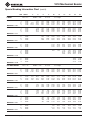
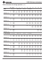
Special Bending Information Chart (cont’d)
DIM ANGLE 2" 4" 6" 8" 10" 12" 15" 18" 24" 36"
1-1/4 EMT Dia.=1.51 Radius=8.53 X=3.34 H=Height
Y 15.00 0.35 8.07 15.80 23.53 31.26 38.98 50.58 62.17 85.35 131.71
L1 15.00 7.71 15.44 23.17 30.90 38.62 46.35 57.94 69.53 92.72 139.08
L2 15.00 9.95 17.68 25.40 33.13 40.86 48.58 60.18 71.77 94.95 141.31
Z 15.00 13.05 20.51 27.98 35.44 42.91 50.37 61.57 72.76 95.16 139.94
MINIMUM H = 1.45
Y 22.50 3.44 8.67 13.90 19.12 24.35 32.19 40.03 55.71 87.06
L1 22.50 10.41 15.64 20.86 26.09 31.31 39.15 46.99 62.67 94.03
L2 22.50 13.76 18.98 24.21 29.44 34.66 42.50 50.34 66.02 97.38
Z 22.50 16.39 21.22 26.05 30.88 35.70 42.95 50.19 64.67 93.65
MINIMUM H = 2.58
Y 30.00 0.86 4.86 8.86 12.86 16.86 22.86 28.86 40.86 64.86
L1 30.00 7.90 11.90 15.90 19.90 23.90 29.90 35.90 47.90 71.90
L2 30.00 12.36 16.36 20.36 24.36 28.36 34.36 40.36 52.36 76.36
Z 30.00 14.84 18.30 21.77 25.23 28.70 33.89 39.09 49.48 70.27
MINIMUM H = 3.96
Y 45.00 0.54 3.37 6.20 9.03 13.27 17.51 26.00 42.97
L1 45.00 10.95 13.78 16.60 20.85 25.09 33.57 50.54
L2 45.00 17.65 20.47 23.30 27.55 31.79 40.27 57.24
Z 45.00 18.41 20.41 22.41 25.41 28.41 34.41 46.41
MINIMUM H = 7.36
Y 60.00 0.10 2.41 4.72 8.18 11.65 18.58 32.43
L1 60.00 12.94 16.40 19.87 26.80 40.65
L2 60.00 21.87 25.34 28.80 35.73 49.58
Z 60.00 20.12 21.85 23.58 27.05 33.97
MINIMUM H = 11.42
Y 90.00 2.38 5.38 11.38 23.38
L1 90.00 20.34 32.34
L2 90.00 33.74 45.74
Z 90.00 20.40 20.40
MINIMUM H = 20.4
Y 15.00 7.43 15.16 22.89 30.61 38.34 49.93 61.52 84.7 131.07
L1 15.00 7.71 15.44 23.17 30.90 38.62 46.35 57.94 69.53 92.72 139.08
L2 15.00 9.95 17.68 25.40 33.13 40.86 48.58 60.18 71.77 94.95 141.31
Z 15.00 13.25 20.71 28.18 35.64 43.11 50.57 61.77 72.96 95.36 140.14
MINIMUM H = 1.50
Y 22.50 2.94 8.17 13.39 18.62 23.85 31.69 39.53 55.2 86.56
L1 22.50 10.41 15.64 20.86 26.09 31.31 39.15 46.99 62.670 94.03
L2 22.50 13.76 18.98 24.21 29.44 34.66 42.5 50.34 66.02 97.38
Z 22.50 16.59 21.42 26.25 31.08 35.9 43.15 50.39 64.87 93.85
MINIMUM H = 2.65
Y 30.00 4.43 8.43 12.43 16.43 22.43 28.43 40.43 64.43
L1 30.00 11.90 15.90 19.90 23.90 29.90 35.90 47.90 71.90
L2 30.00 16.36 20.36 24.36 28.36 34.36 40.36 52.35 76.36
Z 30.00 18.50 21.97 25.43 28.90 34.09 39.29 49.68 70.47
MINIMUM H = 4.06
Y 45.00 0.18 3.01 5.84 8.67 12.91 17.15 25.64 42.61
L1 45.00 10.95 13.78 16.60 20.85 25.09 33.57 50.54
L2 45.00 17.65 20.47 23.30 27.55 31.79 40.27 57.24
Z 45.00 18.61 20.61 22.61 25.61 28.61 34.61 46.61
MINIMUM H = 7.50
Y 60.00 2.08 4.39 7.85 11.32 18.24 32.10
L1 60.00 12.94 16.40 19.87 26.80 40.65
L2 60.00 21.87 25.34 28.80 35.73 49.58
Z 60.00 20.32 22.05 23.78 27.25 34.17
MINIMUM H = 11.60
Y 90.00 2.06 5.06 11.06 23.06
L1 90.00 20.34 32.34
L2 90.00 33.74 45.74
Z 90.00 20.6 20.60
MINIMUM H = 20.6
1-1/2 EMT Dia.=1.74 Radius=8.53 X=3.54 H=Height

Greenlee / A Textron Company 14 4455BoeingDr.•Rockford,IL61109-2988USA•815-397-7070
1818 Mechanical Bender
Y 15.00 5.52 13.25 20.97 28.70 36.43 48.02 59.61 82.79 129.16
L1 15.00 7.71 15.44 23.17 30.90 38.62 46.35 57.94 69.53 92.71 139.08
L2 15.00 10.19 17.92 25.64 33.37 41.10 48.83 60.42 72.01 95.19 141.56
Z 15.00 14.39 21.86 29.32 36.79 44.25 51.72 62.91 74.11 96.50 141.28
MINIMUM H = 1.80
Y 22.50 1.26 6.48 11.71 16.94 22.16 30.00 37.84 53.52 84.88
L1 22.50 10.40 15.63 20.86 26.08 31.31 39.15 46.99 62.67 94.02
L2 22.50 14.12 19.35 24.57 29.80 35.02 42.86 50.70 66.38 97.74
Z 22.50 17.86 22.69 27.52 32.35 37.17 44.42 51.66 66.14 95.12
MINIMUM H = 3.14
Y 30.00 2.83 6.83 10.83 14.83 20.83 26.83 38.83 62.83
L1 30.00 11.88 15.88 19.88 23.88 29.88 35.88 47.88 71.88
L2 30.00 16.84 20.84 24.84 28.84 34.84 40.84 52.84 76.84
Z 30.00 19.90 23.37 26.83 30.29 35.49 40.69 51.08 71.86
MINIMUM H = 4.75
Y 45.00 1.40 4.23 7.06 11.30 15.54 24.03 41.00
L1 45.00 13.74 16.56 20.81 25.05 33.53 50.50
L2 45.00 21.16 23.99 28.24 32.48 40.96 57.93
Z 45.00 22.28 24.28 27.28 30.28 36.28 48.28
MINIMUM H = 8.68
Y 60.00 0.38 2.68 6.15 9.61 16.54 30.40
L1 60.00 16.30 19.77 26.70 40.55
L2 60.00 26.21 29.67 36.60 50.46
Z 60.00 24.02 25.76 29.22 36.15
MINIMUM H = 13.31
Y 90.00 3.00 9.00 21.00
L1 90.00 19.94 31.94
L2 90.00 34.80 46.80
Z 90.00 23.36 23.36
MINIMUM H = 23.36
Y 15.00 2.90 10.63 18.36 26.09 33.81 41.54 53.13 64.72 87.91 134.27
L1 15.00 7.72 15.45 23.18 30.91 38.63 46.36 57.95 69.54 92.72 139.09
L2 15.00 8.44 16.17 23.90 31.62 39.35 47.08 58.67 70.26 93.44 139.81
Z 15.00 11.03 18.49 25.95 33.42 40.88 48.35 59.54 70.74 93.13 137.92
MINIMUM H = 9.22
Y 22.50 0.74 5.97 11.20 16.42 21.65 26.87 34.71 42.55 58.23 89.59
L1 22.50 5.21 10.44 15.66 20.89 26.12 31.34 39.18 47.02 62.70 94.06
L2 22.50 6.29 11.51 16.74 21.97 27.19 32.42 40.26 48.10 63.78 95.13
Z 22.50 8.76 13.59 18.42 23.24 28.07 32.90 40.14 47.39 61.87 90.84
MINIMUM H = 1.50
Y 30.00 3.59 7.59 11.59 15.59 19.59 25.59 31.59 43.59 67.59
L1 30.00 7.97 11.97 15.97 19.97 23.97 29.97 35.97 47.97 71.97
L2 30.00 9.40 13.40 17.40 21.40 25.40 31.40 37.40 49.40 73.40
Z 30.00 11.24 14.70 18.16 21.63 25.09 30.29 35.49 45.88 66.66
MINIMUM H = 2.15
Y 45.00 1.09 3.92 6.74 9.57 12.40 16.64 20.89 29.37 46.34
L1 45.00 5.54 8.37 11.20 14.02 16.85 21.10 25.34 33.82 50.79
L2 45.00 7.69 10.52 13.35 16.18 19.00 23.25 27.49 35.98 52.95
Z 45.00 9.11 11.11 13.11 15.11 17.11 20.11 23.11 29.11 41.11
MINIMUM H = 3.61
Y 60.00 2.02 4.33 6.64 8.95 12.41 15.88 22.81 36.66
L1 60.00 6.63 8.94 11.25 13.56 17.03 20.49 27.42 41.27
L2 60.00 9.50 11.81 14.12 16.43 19.90 23.36 30.29 44.14
Z 60.00 9.47 10.62 11.78 12.93 14.66 16.40 19.86 26.79
MINIMUM H = 5.20
Y 90.00 2.00 4.00 6.00 9.00 12.00 18.00 30.00
L1 90.00 8.82 10.82 13.82 16.82 22.82 34.82
L2 90.00 13.13 15.13 18.13 21.13 27.13 39.13
Z 90.00 8.32 8.32 8.32 8.32 8.32 8.32
MINIMUM H = 8.32
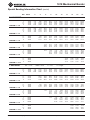
DIM ANGLE 2" 4" 6" 8" 10" 12" 15" 18" 24" 36"
2 EMT Dia.=2.2 Radius=9.46 X=4.44 H=Height
1/2 IMC/RIGID Dia.=.84 Radius=2.74 X=2.84 H=Height
Special Bending Information Chart (cont’d)

Greenlee / A Textron Company 15 4455BoeingDr.•Rockford,IL61109-2988USA•815-397-7070
1818 Mechanical Bender
Y 15.00 2.23 9.96 17.69 25.41 33.14 40.87 52.46 64.05 87.23 133.60
L1 15.00 7.72 15.45 23.18 30.90 38.63 46.36 57.95 69.54 92.72 139.09
L2 15.00 8.97 16.69 24.42 32.15 39.88 47.60 59.19 70.79 93.97 140.33
Z 15.00 11.56 19.02 26.49 33.95 41.41 48.88 60.07 71.27 93.66 138.45
MINIMUM H = 1.06
Y 22.50 0.07 5.29 10.52 15.75 20.97 26.20 34.04 41.88 57.56 88.91
L1 22.50 5.20 10.43 15.65 20.88 26.11 31.33 39.17 47.01 62.69 94.05
L2 22.50 7.07 12.30 17.52 22.75 27.98 33.20 41.04 48.88 64.56 95.92
Z 22.50 9.56 14.39 19.22 24.05 28.88 33.70 40.95 48.19 62.67 91.65
MINIMUM H = 1.81
Y 30.00 2.83 6.83 10.83 14.83 18.83 24.83 30.83 42.83 66.83
L1 30.00 7.94 11.94 15.94 19.94 23.94 29.94 35.94 47.94 71.94
L2 30.00 10.43 14.43 18.43 22.43 26.43 32.43 38.43 50.43 74.43
Z 30.00 12.32 15.78 19.25 22.71 26.18 31.37 36.57 46.96 67.74
MINIMUM H = 2.70
Y 45.00 0.10 2.93 5.76 8.59 11.42 15.66 19.90 28.39 45.36
L1 45.00 8.28 11.11 13.94 16.77 21.01 25.25 33.74 50.71
L2 45.00 12.02 14.85 17.68 20.50 24.75 28.99 37.47 54.45
Z 45.00 12.78 14.78 16.78 18.78 21.78 24.78 30.78 42.78
MINIMUM H = 4.80
Y 60.00 0.73 3.04 5.35 7.66 11.13 14.59 21.52 35.37
L1 60.00 8.73 11.04 13.34 16.81 20.27 27.20 41.06
L2 60.00 13.71 16.02 18.33 21.79 25.26 32.19 46.04
Z 60.00 12.96 14.11 15.26 17.00 18.73 22.19 29.12
MINIMUM H = 7.22
Y 90.00 1.38 3.88 6.88 9.88 15.88 27.88
L1 90.00 12.96 15.96 21.96 33.96
L2 90.00 20.43 23.43 29.43 41.43
Z 90.00 12.36 12.36 12.36 12.36
MINIMUM H = 12.36
Y 15.00 0.85 8.58 16.31 24.03 31.76 39.49 51.08 62.67 85.85 132.22
L1 15.00 7.72 15.45 23.17 30.90 38.63 46.36 57.95 69.54 92.72 139.08
L2 15.00 9.30 17.03 24.76 32.48 40.21 47.94 59.53 71.12 94.30 140.67
Z 15.00 12.60 20.06 27.53 34.99 42.45 49.92 61.11 72.31 94.70 139.49
MINIMUM H = 1.33
Y 22.50 3.99 9.22 14.44 19.67 24.90 32.74 40.57 56.25 87.61
L1 22.50 10.42 15.65 20.87 26.10 31.33 39.17 47.01 62.68 94.04
L2 22.50 12.80 18.02 23.25 28.48 33.70 41.54 49.38 65.06 96.42
Z 22.50 15.60 20.43 25.26 30.09 34.92 42.16 49.40 63.89 92.86
MINIMUM H = 2.28
Y 30.00 1.52 5.52 9.52 13.52 17.52 23.52 29.52 41.52 65.52
L1 30.00 7.93 11.93 15.93 19.93 23.93 29.93 35.93 47.93 71.93
L2 30.00 11.09 15.09 19.09 23.09 27.09 33.09 39.09 51.09 75.09
Z 30.00 13.71 17.17 20.64 24.10 27.57 32.76 37.96 48.35 69.14
MINIMUM H = 3.39
Y 45.00 1.51 4.34 7.17 9.99 14.24 18.48 26.97 43.94
L1 45.00 11.05 13.88 16.71 20.95 25.20 33.68 50.65
L2 45.00 15.81 18.63 21.46 25.70 29.95 38.43 55.40
Z 45.00 16.55 18.55 20.55 23.55 26.55 32.55 44.55
MINIMUM H = 6.05
Y 60.00 1.45 3.75 6.06 9.53 12.99 19.92 33.78
L1 60.00 10.90 13.21 16.67 20.13 27.06 40.92
L2 60.00 17.23 19.54 23.01 26.47 33.40 47.25
Z 60.00 16.30 17.45 19.19 20.92 24.38 31.31
MINIMUM H = 9.12
Y 90.00 1.75 4.75 7.75 13.75 25.75
L1 90.00 15.40 21.40 33.40
L2 90.00 24.91 30.91 42.91
Z 90.00 15.64 15.64 15.64
MINIMUM H = 15.64
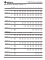
3/4 IMC/RIGID Dia.=1.05 Radius=4.76 X=2.84 H=Height
DIM ANGLE 2" 4" 6" 8" 10" 12" 15" 18" 24" 36"
Special Bending Information Chart (cont’d)
1 IMC/RIGID
Dia.=1.315 Radius=6.05 X=3.54 H=Height

Greenlee / A Textron Company 16 4455BoeingDr.•Rockford,IL61109-2988USA•815-397-7070
1818 Mechanical Bender
Y 15.00 7.30 15.02 22.75 30.48 38.21 49.80 61.39 84.57 130.94
L1 15.00 7.72 15.44 23.17 30.90 38.63 46.35 57.94 69.54 92.72 139.08
L2 15.00 9.71 17.43 25.16 32.89 40.62 48.34 59.93 71.52 94.71 141.07
Z 15.00 13.42 20.88 28.34 35.81 43.27 50.74 61.93 73.13 95.52 140.30
MINIMUM H = 1.54
Y 22.50 2.82 8.05 13.27 18.50 23.73 31.57 39.41 55.08 86.44
L1 22.50 10.41 15.64 20.87 26.09 31.32 39.16 47.00 62.68 94.03
L2 22.50 13.40 18.62 23.85 29.08 34.30 42.14 49.98 65.66 97.02
Z 22.50 16.63 21.46 26.29 31.12 35.94 43.19 50.43 64.91 93.89
MINIMUM H = 2.67
Y 30.00 0.35 4.35 8.35 12.35 16.35 22.35 28.35 40.35 64.35
L1 30.00 11.91 15.91 19.91 23.91 29.91 35.91 47.91 71.91
L2 30.00 15.89 19.89 23.89 27.89 33.89 39.89 51.89 75.89
Z 30.00 18.42 21.88 25.34 28.81 34.00 39.20 49.59 70.38
MINIMUM H = 4.01
Y 45.00 0.21 3.04 5.87 8.70 12.94 17.18 25.67 42.64
L1 45.00 10.99 13.82 16.64 20.89 25.13 33.61 50.58
L2 45.00 16.96 19.78 22.61 26.86 31.10 39.58 56.55
Z 45.00 18.25 20.25 22.25 25.25 28.25 34.25 46.25
MINIMUM H = 7.25
Y 60.00 2.25 4.56 8.02 11.49 18.42 32.27
L1 60.00 13.04 16.50 19.97 26.90 40.75
L2 60.00 21.00 24.46 27.93 34.85 48.71
Z 60.00 19.65 21.39 23.12 26.58 33.51
MINIMUM H = 11.02
Y 90.00 2.62 5.62 11.62 23.62
L1 90.00 20.74 32.74
L2 90.00 32.68 44.68
Z 90.00 19.15 19.15
MINIMUM H = 19.15
Y 15.00 5.78 13.51 21.24 28.97 36.69 48.28 59.88 83.06 129.42
L1 15.00 7.71 15.44 23.17 30.9 38.62 46.35 57.94 69.53 92.71 139.08
L2 15.00 10.14 17.87 25.60 33.32 41.05 48.78 60.37 71.96 95.14 141.51
Z 15.00 14.68 22.15 29.61 37.08 44.54 52.01 63.20 74.40 96.79 141.57
MINIMUM H = 1.87
Y 22.50 1.35 6.57 11.80 17.02 22.25 30.09 37.93 53.61 84.97
L1 22.50 10.40 15.63 20.86 26.08 31.31 39.15 46.99 62.67 94.03
L2 22.50 14.05 19.27 24.50 29.72 34.95 42.79 50.63 66.31 97.67
Z 22.50 18.12 22.95 27.78 32.61 37.44 44.68 51.92 66.41 95.38
MINIMUM H = 3.2
Y 30.00 2.84 6.84 10.84 14.84 20.84 26.84 38.84 62.84
L1 30.00 11.89 15.89 19.89 23.89 29.89 35.89 47.89 71.89
L2 30.00 16.74 20.74 24.74 28.74 34.74 40.74 52.74 76.74
Z 30.00 20.14 23.60 27.07 30.53 35.73 40.92 51.32 72.10
MINIMUM H = 4.87
Y 45.00 1.35 4.18 7.01 11.25 15.49 23.98 40.95
L1 45.00 13.74 16.57 20.81 25.06 33.54 50.51
L2 45.00 21.02 23.85 28.09 32.34 40.82 57.79
Z 45.00 22.46 24.46 27.46 30.46 36.46 48.46
MINIMUM H = 8.81
Y 60.00 0.32 2.63 6.09 9.56 16.48 30.34
L1 60.00 16.32 19.79 26.72 40.57
L2 60.00 26.03 29.50 36.42 50.28
Z 60.00 24.14 25.88 29.34 36.27
MINIMUM H = 13.41
Y 90.00 3.00 9.00 21.00
L1 90.00 20.02 32.02
L2 90.00 34.58 46.58
Z 90.00 23.32 23.32
MINIMUM H = 23.32
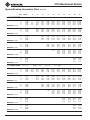
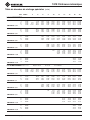
DIM ANGLE 2" 4" 6" 8" 10" 12" 15" 18" 24" 36"
1-1/4 IMC/RIGID Dia.=1.66 Radius=7.6 X=3.95 H=Height
Special Bending Information Chart (cont’d)
1-1/2 IMC/RIGID
Dia.=1.9 Radius=9.27 X=4.78 H=Height

Greenlee / A Textron Company 17 4455BoeingDr.•Rockford,IL61109-2988USA•815-397-7070
1818 Mechanical Bender
2 IMC/RIGID Dia.=2.375 Radius=10.78 X=4.35 H=Height
DIM ANGLE 2" 4" 6" 8" 10" 12" 15" 18" 24" 36"
Y 15.00 5.10 12.82 20.55 28.28 36.01 47.60 59.19 82.37 128.74
L1 15.00 7.71 15.44 23.17 30.89 38.62 46.35 57.94 69.53 92.71 139.08
L2 15.00 10.53 18.26 25.99 33.72 41.44 49.17 60.76 72.35 95.53 141.9
Z 15.00 14.65 22.12 29.58 37.04 44.51 51.97 63.17 74.37 96.76 141.54
MINIMUM H = 1.86
Y 22.50 0.86 6.08 11.31 16.53 21.76 29.60 37.44 53.12 84.48
L1 22.50 10.40 15.62 20.85 26.08 31.30 39.14 46.98 62.66 94.02
L2 22.50 14.63 19.86 25.08 30.31 35.54 43.37 51.21 66.89 98.25
Z 22.50 18.30 23.12 27.95 32.78 37.61 44.85 52.09 66.58 95.55
MINIMUM H = 3.31
Y 30.00 2.39 6.39 10.39 14.39 20.39 26.39 38.39 62.39
L1 30.00 11.87 15.87 19.87 23.87 29.87 35.87 47.87 71.87
L2 30.00 17.51 21.51 25.51 29.51 35.51 41.51 53.51 77.51
Z 30.00 20.52 23.98 27.45 30.91 36.11 41.30 51.70 72.48
MINIMUM H = 5.06
Y 45.00 0.82 3.65 6.48 10.72 14.96 23.45 40.42
L1 45.00 13.68 16.51 20.75 24.99 33.48 50.45
L2 45.00 22.14 24.97 29.22 33.46 41.94 58.91
Z 45.00 23.28 25.28 28.28 31.28 37.28 49.28
MINIMUM H = 9.39
Y 60.00 1.91 5.38 8.84 15.77 29.62
L1 60.00 16.16 19.63 26.55 40.41
L2 60.00 27.45 30.91 37.84 51.70
Z 60.00 25.46 27.19 30.65 37.58
MINIMUM H = 14.55
Y 90.00 1.68 7.68 19.68
L1 90.00 31.37
L2 90.00 48.31
Z 90.00 25.91
MINIMUM H = 25.91
Special Bending Information Chart (cont’d)

Greenlee / A Textron Company 18 4455BoeingDr.•Rockford,IL61109-2988USA•815-397-7070
1818 Mechanical Bender

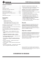
1818
Cintreuse mécanique
Toutes cintreuses de numéro de série YY-0000 et au-dessus
MANUEL D’INSTRUCTIONS
Nousvousconseillonsdelire attentivement et de
bien comprendre les instructions suivantes avant
d’utiliseroudeprocéderàl’entretiendecetoutil.
Enregistrez votre produit en ligne, www.greenlee.com
99901404 © 2012 Greenlee Textron Inc. IM 1101 REV 16 5/12

Greenlee / A Textron Company 20 4455BoeingDr.•Rockford,IL61109-2988USA•815-397-7070
1818 Cintreuse mécanique
Touteslesspécicationssontnominalesetpeuventchangeravec
l’améliorationdelaconception.GreenleeTextronnepeutêtretenue
responsabledesdommagesrésultantd’uneapplicationinappropriée
oud’unmauvaisusagedesesproduits.
CONSERVEZ CE MANUEL
Table des matières
Description ................................................................... 20
Sécurité ........................................................................ 20
Objet de ce manuel ...................................................... 20
Informationsdesécuritéimportantes........................... 21
Instructions de cintrage ........................................... 22-26
Donnéesdecintragespéciales ...............................27-29
Tablesdedonnéesdecintragespéciales ...............30-35
Illustration ..................................................................... 37
Nomenclaturedespièces ............................................. 38
Description
Capacité
EMTde3/4poà2po
IMCde1/2poà1-1/4po
Conduitrigidegalvaniséde1/2poà1-1/2po
Conduitrigidealuminium(seulement)de2po
Remarque : le rayon de cintrage est clairement marqué
sur chaque sabot de cintrage.
Lacintreusemécanique1818estconçuepouroffrirdes
annéesdeserviceable.
Lescaractéristiquessuivantesfontdelacintreuse
1818l’undesoutilslesplusutilesetpolyvalentssurle
marché.
• Cliquetintégré—permetd’appliquerdescoups
courts et puissants pour effectuer un cintrage plus
rapide.
• Guidedepositionnementdesabot—facilitele
chargement.Larotationdusabotestrestreinte.
• Indicateurdedegrésdecintrage—permetd’assurer
des cintrages toujours exacts.
• Railssuiveurs—produitdescintragesréguliersde
tubesEMTde1-1/4po,1-1/2poet2posansplini
cassure.
• Rouesencaoutchouc—déplacementsfacilesà
l’atelierousurlechantier.
• Châssisrobuste—tientlacintreuseenplacedurant
le cintrage.
• Modedecintragerapide—actionnementsanscliquet
pour le cintrage de conduits de petite section.
Ce qui fait la supériorité de la cintreuse 1818
• Nenécessiteaucunecaissederangement.Tousles
sabotspeuventêtrerangéssurlacintreuse.
Remarque : les rails suiveurs, les galets et les broches
se placent dans la cintreuse et l’ensemble peut être
enchaîné à un poteau pour la sécurité.
• Lechariotminimiseleéchissementlorsducintrage
de conduits de grande section.
• Lechâssisenaciernenécessitepasdebarre
d’amarragepoursoutenirlesystèmedecintrage.
• L’ensemblesabotetsegmentàrochetest
automatiquementretenuparleboutondefriction
durantlechargementduconduit.Cesystèmede
blocagesedégageautomatiquement.
• Lechâssisacceptelessabots,legaletdecalageet
lesrailssuiveurs1818existants.
Sécurité
Lorsdel’utilisationetdel’entretiendesoutilsetde
l’équipementdeGreenlee,votresécuritéestune
priorité.Ensuivantlesinstructionsdecemanuelet
cellesinscritessurl’outil,vouspourrezéliminerles
risquesetlesdangersliésàsonutilisation.Respectez
touteslesconsignesdesécurité.
Objet de ce manuel
Cemanueld’instructionsapourobjetdefamiliariserle
personnelaveclesprocédurespréconiséespourune
utilisation et un entretien sans danger de la cintreuse
mécanique1818deGreenlee.
Mettezcemanuelàladispositiondetouslesemployés.
On peut obtenir des exemplaires gratuits sur simple
demandewww.greenlee.com.
La page est en cours de chargement...
La page est en cours de chargement...
La page est en cours de chargement...
La page est en cours de chargement...
La page est en cours de chargement...
La page est en cours de chargement...
La page est en cours de chargement...
La page est en cours de chargement...
La page est en cours de chargement...
La page est en cours de chargement...
La page est en cours de chargement...
La page est en cours de chargement...
La page est en cours de chargement...
La page est en cours de chargement...
La page est en cours de chargement...
La page est en cours de chargement...
La page est en cours de chargement...
La page est en cours de chargement...
La page est en cours de chargement...
La page est en cours de chargement...
-
 1
1
-
 2
2
-
 3
3
-
 4
4
-
 5
5
-
 6
6
-
 7
7
-
 8
8
-
 9
9
-
 10
10
-
 11
11
-
 12
12
-
 13
13
-
 14
14
-
 15
15
-
 16
16
-
 17
17
-
 18
18
-
 19
19
-
 20
20
-
 21
21
-
 22
22
-
 23
23
-
 24
24
-
 25
25
-
 26
26
-
 27
27
-
 28
28
-
 29
29
-
 30
30
-
 31
31
-
 32
32
-
 33
33
-
 34
34
-
 35
35
-
 36
36
-
 37
37
-
 38
38
-
 39
39
-
 40
40


Greenlee 1818 Mechanical Bender - Serial No. YY and up Manuel utilisateur
- Taper
- Manuel utilisateur
Documents connexes
-
Greenlee 555DX Manuel utilisateur
-
-
-
-
-
-
-
-
-
