MULTIPLEX Multiplex 21 4264 Le manuel du propriétaire
- Catégorie
- Jouets télécommandés
- Taper
- Le manuel du propriétaire
Ce manuel convient également à

1
BK / KIT Solius # 21 4264
vorgesehen für den MULTIPLEX
Brushless-Antrieb # 33 2660 / 33 3660
Designed for the MULTIPLEX
brushless power set # 33 2660 / 33 3660
F
GB
D
E
I
Bauanleitung
2 ... 112 ... 11
2 ... 112 ... 11
2 ... 11
Building instructions 12 ... 21
Notice de construction 22 ... 37
Instruzioni di montaggio 38 ... 47
Instrucciones de montaje 48 ... 57
Ersatzteile
Replacement parts
Pièces de rechanges
Parti di ricambio
Repuestos
58 ... 60
© Copyright by MULTIPLEX 2013 Version 1.1

2
Sicherheitshinweise für MULTIPLEX-Flugmodelle
Das Modell ist KEIN SPIELZEUG im üblichen Sinne.
Mit Inbetriebnahme des Modells erklärt der Betreiber, dass er den Inhalt der Betriebsanleitung, besonders zu Sicherheitshin-
weisen, Wartungsarbeiten, Betriebsbeschränkungen und Mängel kennt und inhaltlich nachvollziehen kann.
Dieses Modell darf nicht von Kindern unter 14 Jahren betrieben werden. Betreiben Minderjährige das Modell unter der
Aufsicht eines, im Sinne des Gesetzes, fürsorgepflichtigen und sachkundigen Erwachsenen, ist dieser für die Umsetzung
der Hinweise der BETRIEBSANLEITUNG verantwortlich.
DAS MODELL UND DAZUGEHÖRIGES ZUBEHÖR MUSS VON KINDERN UNTER 3 JAHREN FERNGEHALTEN WER-
DEN! ABNEHMBARE KLEINTEILE DES MODELLS KÖNNEN VON KINDERN UNTER 3 JAHREN VERSCHLUCKT WER-
DEN. ERSTICKUNGSGEFAHR!
Beim Betrieb des Modells müssen alle Warnhinweise der BETRIEBSANLEITUNG beachtet werden. Die Multiplex Modells-
port GmbH & Co. KG ist nicht haftungspflichtig für Verluste und Beschädigungen jeder Art, die als Folge falschen Betriebes
oder Missbrauches dieses Produktes, einschließlich der dazu benötigten Zubehörteile entstehen. Dies beinhaltet direkte,
indirekte, beabsichtigte und unabsichtliche Verluste und Beschädigungen und jede Form von Folgeschäden.
Jeder Sicherheitshinweis dieser Anleitung muss unbedingt befolgt werden und trägt unmittelbar zum sicheren Betrieb Ihres
Modells bei. Benutzen Sie Ihr Modell mit Verstand und Vorsicht, und es wird Ihnen und Ihren Zuschauern viel Spaß bereiten,
ohne eine Gefahr darzustellen. Wenn Sie Ihr Modell nicht verantwortungsbewusst betreiben, kann dies zu erheblichen
Sachbeschädigungen und schwerwiegenden Verletzungen führen. Sie alleine sind dafür verantwortlich, dass die Betriebsan-
leitungen befolgt und die Sicherheitshinweise in die Tat umgesetzt werden.
Bestimmungsgemäße Verwendung
Das Modell darf ausschließlich im Hobbybereich verwendet werden. Jede weitere Verwendung darüber hinaus ist nicht
erlaubt. Für Schäden oder Verletzungen an Menschen und Tieren aller Art haftet ausschließlich der Betreiber des Modells
und nicht der Hersteller.
Zum Betrieb des Modells darf nur das von uns empfohlene Zubehör verwendet werden. Die empfohlenen Komponenten sind
erprobt und auf eine sichere Funktion passend zum Modell abgestimmt. Werden andere Komponenten verwendet oder das
Modell verändert, erlöschen alle Ansprüche an den Hersteller bzw. den Vertreiber.
Um das Risiko beim Betrieb des Modells möglichst gering zu halten, beachten Sie folgende Punkte:
Das Modell wird über eine Funkfernsteuerung gelenkt. Keine Funkfernsteuerung ist sicher vor Funkstörungen.
Solche Störungen können dazu führen, dass Sie zeitweise die Kontrolle über Ihr Modell verlieren. Deshalb müssen
Sie beim Betrieb Ihres Modells zur Vermeidung von Kollisionen immer auf große Sicherheitsräume in allen Richtun-
gen achten. Schon beim kleinsten Anzeichen von Funkstörungen müssen Sie den Betrieb Ihres Modells einstellen!
Sie dürfen Ihr Modell erst in Betrieb nehmen, nachdem Sie einen kompletten Funktionstest und einen Reichweiten-
test, gemäß der Anleitung Ihrer Fernsteuerung, erfolgreich ausgeführt haben.
Das Modell darf nur bei guten Sichtverhältnissen geflogen werden. Fliegen Sie nicht in Richtung Sonne, um nicht
geblendet zu werden, oder bei anderen schwierigen Lichtverhältnissen.
Ein Modell darf nicht unter Alkohol-Einfluss oder Einfluss von anderen Rauschmitteln oder Medikamenten betrieben
werden, die das Wahrnehmungs- und Reaktionsvermögen beeinträchtigen.
Fliegen Sie nur bei Wind- und Wetterverhältnissen, bei denen Sie das Modell sicher beherrschen können. Berück-
sichtigen Sie auch bei schwachem Wind, dass sich Wirbel an Objekten bilden, die auf das Modell Einfluss nehmen
können.
Fliegen Sie nie an Orten, an denen Sie andere oder sich selbst gefährden können, wie z.B. Wohngebiete, Überland-
leitungen, Straßen und Bahngleise.
Niemals auf Personen und Tiere zufliegen. Anderen Leuten dicht über die Köpfe zu fliegen ist kein Zeichen für
wirkliches Können, sondern setzt andere Leute nur ein unnötiges Risiko aus. Weisen Sie auch andere Piloten in
unser aller Interesse auf diese Tatsache hin. Fliegen Sie immer so, dass weder Sie noch andere in Gefahr kommen.
Denken Sie immer daran, dass auch die allerbeste Fernsteuerung jederzeit gestört werden kann. Auch langjährige,
unfallfreie Flugpraxis ist keine Garantie für die nächste Flugminute.
D

3
Restrisiken
Auch wenn das Modell vorschriftsmäßig und unter Beachtung aller Sicherheitsaspekten betrieben wird, besteht immer ein
gewisses Restrisiko.
Eine Haftpflichtversicherung ist daher obligatorisch. Falls Sie in einen Verein oder Verband eintreten, können Sie diese
Versicherung dort abschließen. Achten Sie auf ausreichenden Versicherungsschutz (Modellflugzeug mit Antrieb). Halten
Sie Modelle und Fernsteuerung immer absolut in Ordnung.
Folgende Gefahren können im Zusammenhang mit der Bauweise und Ausführung des Modells auftreten:
Verletzungen durch die Luftschraube: Sobald der Akku angeschlossen ist, ist der Bereich um die Luftschraube
freizuhalten. Beachten Sie auch, dass Gegenstände vor der Luftschraube angesaugt werden können oder Gegen-
stände dahinter weggeblasen werden können. Das Modell kann sich in Bewegung setzen. Richten Sie es daher
immer so aus, dass es sich im Falle eines ungewollten Anlaufen des Motors nicht in Richtung anderer Personen
bewegen kann. Bei Einstellarbeiten, bei denen der Motor läuft oder anlaufen kann, muss das Modell stets von
einem Helfer sicher festgehalten werden.
Absturz durch Steuerfehler: Kann dem besten Piloten passieren, deshalb nur in sicherer Umgebung fliegen; ein
zugelassenes Modellfluggelände und eine entsprechende Versicherung sind unabdingbar.
Absturz durch technisches Versagen oder unentdeckten Transport- oder Vorschaden. Die sorgfältige Überprüfung
des Modells vor jedem Flug ist ein Muss. Es muss jedoch immer damit gerechnet werden, dass es zu Material-
versagen kommen kann. Niemals an Orten fliegen, an denen man Anderen Schaden zufügen kann.
Betriebsgrenzen einhalten. Übermäßig hartes Fliegen schwächt die Struktur und kann entweder zu plötzlichem
Materialversagen führen, oder bei späteren Flügen das Modell aufgrund von „schleichenden“ Folgeschäden abstür-
zen lassen.
Feuergefahr durch Fehlfunktion der Elektronik. Akkus sicher aufbewahren, Sicherheitshinweise der Elektronik-
komponenten im Modell, des Akkus und des Ladegerätes beachten, Elektronik vor Wasser schützen. Auf ausrei-
chende Kühlung bei Regler und Akku achten.
Die Anleitungen unserer Produkte dürfen nicht ohne ausdrückliche Erlaubnis der Multiplex Modellsport GmbH &
Co. KG (in schriftlicher Form) - auch nicht auszugsweise in Print- oder elektronischen Medien reproduziert und /
oder veröffentlicht werden.

4
D
KIT Solius # 21 4264
Machen Sie sich mit dem Bausatz vertraut!
MULTIPLEX - Modellbaukästen unterliegen während der Produktion einer ständigen Materialkontrolle. Wir hoffen, dass Sie
mit dem Baukasteninhalt zufrieden sind. Wir bitten Sie jedoch, alle Teile (nach Stückliste) vor Verwendung zu prüfen, da
bearbeitete Teile vom Umtausch ausgeschlossen sind. Sollte ein Bauteil einmal nicht in Ordnung sein, sind wir nach
Überprüfung gern zur Nachbesserung oder zum Umtausch bereit. Senden Sie das Teil, bitte ausreichend frankiert, an
unseren Service ein und fügen Sie unbedingt die vollständig ausgefüllte Reklamationsmeldung (Formular) bei. Wir arbeiten
ständig an der technischen Weiterentwicklung unserer Modelle. Änderungen des Baukasteninhalts in Form, Maß, Technik,
Material und Ausstattung behalten wir uns jederzeit und ohne Ankündigung vor. Bitte haben Sie Verständnis dafür, dass aus
Angaben und Abbildungen dieser Anleitung keine Ansprüche abgeleitet werden können.
Achtung!
Ferngesteuerte Modelle, insbesondere Flugmodelle, sind kein Spielzeug im üblichen Sinne. Ihr Bau und Be-
trieb erfordert technisches Verständnis, ein Mindestmaß an handwerklicher Sorgfalt sowie Disziplin und
Sicherheitsbewusstsein.
Fehler und Nachlässigkeiten beim Bau und Betrieb können Personen- und Sachschäden zur Folge haben. Da der Hersteller
keinen Einfluss auf ordnungsgemäßen Zusammenbau, Wartung und Betrieb hat, weisen wir ausdrücklich auf diese Gefah-
ren hin.
Warnung:
Das Modell hat, wie jedes Flugzeug, statische Grenzen! Sturzflüge und unsinnige Manöver im Unverstand können zum
Verlust des Modells führen. Beachten Sie: In solchen Fällen gibt es von uns keinen Ersatz. Tasten Sie sich also vorsichtig
an die Grenzen heran. Das Modell ist auf den von uns empfohlenen Antrieb ausgelegt, kann aber nur einwandfrei gebaut und
unbeschädigt den Belastungen standhalten.
Fernsteuerelemente im Modell / sonstiges Zubehör
Empfohlene Ausrüstung:
MULTIPLEX Empfänger ab RX-5 light M-LINK Best. Nr. 5 5808
oder RX-6-DR light M-LINK Best. Nr. 5 5809
Dazu können Sie auch auf unsere telemetriefähigen M-LINK-Empfänger zurückgreifen und Ihr Modell beispielsweise mit
dem Vario-/Höhe-Sensor und Strom-Sensor ausstatten.
2x Servos Nano-S (2x Quer) Best. Nr. 6 5120
2x Servos Tiny-S (Höhe + Seite) Best. Nr. 6 5121
2x Servoverlängerungskabel 40 cm Best. Nr. 8 5029 (für Querruder im Rumpf)
2x Servoverlängerungskabel 40 cm Best. Nr. 8 5029 (für Querruder in den Tragflächen)
2x Servoverlängerungskabel 60 cm Best. Nr. 8 5032 (für Höhen- und Seitenruder)
Antriebssatz mit passendem Antriebsakku:
Antriebsatz "Solius" Li-BATT powered Best. Nr. 33 3660
mit Brushless-Motor BL-O 3516-0850, Regler MULTIcont BL 40 S-BEC sowie
Antriebsakku Li-BATT eco 3/2200 (M6)
=> Klapp-Luftschraube 12x6", Mitnehmer, Spinner und Zubehör liegen bereits dem Baukasten bei!
Antriebssatz:
Antriebsatz "Solius" Best. Nr. 33 2660
mit Brushless-Motor BL-O 3516-0850, Regler MULTIcont BL 40 S-BEC
=> Klapp-Luftschraube 12x6", Mitnehmer, Spinner und Zubehör liegen bereits dem Baukasten bei!
Akkuempfehlung:
Li-BATT FX 3/1-2200 (M6) Best. Nr. 15 7351
Klebstoff:
Zacki ELAPOR ® 20g Best.-Nr. 59 2727
Zacki ELAPOR ® Super liquid 10g Best.-Nr. 59 2728
Heisskleber, Kontaktkleber für Kabinenhaube
Ladegerät:
Combo MULTIcharger LN-3008 EQU mit Netzgerät AC/DC 230V/12V 5,0A
Best.-Nr. 9 2545
Werkzeuge:
Klingenmesser, Seitenschneider, Schraubendreher (für M3 und M5), Steckschlüssel SW 13, Heissklebe-Pistole.

5
Wichtiger Hinweis
Dieses Modell ist nicht aus Styropor ™! Daher sind Verklebungen mit Weißleim, Polyurethan oder Epoxy nicht möglich.
Diese Kleber haften nur oberflächlich und platzen im Ernstfall einfach ab. Verwenden Sie nur Cyanacrylat-/Sekundenkleber
mittlerer Viskosität, vorzugsweise Zacki -ELAPOR® # 59 2727, der für ELAPOR® Partikelschaum optimierte und angepasste
Sekundenkleber. Bei Verwendung von Zacki-ELAPOR® können Sie auf Kicker oder Aktivator weitgehend verzichten. Wenn
Sie jedoch andere Kleber verwenden, und auf Kicker/Aktivator nicht verzichten können, sprühen Sie aus gesundheitlichen
Gründen nur im Freien. Vorsicht beim Arbeiten mit allen Cyanacrylatklebern. Diese Kleber härten u.U. in Sekunden, daher
nicht mit den Fingern und anderen Körperteilen in Verbindung bringen. Zum Schutz der Augen unbedingt Schutzbrille tragen!
Von Kindern fernhalten! An einigen Stellen ist es auch möglich Heißkleber zu verwenden. Wir weisen in der Anleitung ggf.
darauf hin!
Arbeiten mit Zacki ELAPOR®
Zacki ELAPOR® wurde speziell für die Verklebung für unsere Schaummodelle aus ELAPOR® entwickelt.
Um die Verklebung möglichst optimal zu gestalten, sollten Sie folgende Punkte beachten:
• Vermeiden Sie den Einsatz von Aktivator. Durch ihn wird die Verbindung deutlich geschwächt.
Vor allem bei großflächiger Verklebung empfehlen wir, die Teile 24 h trocken zu lassen.
• Aktivator ist lediglich zum punktuellen Fixieren zu verwenden. Sprühen Sie nur wenig Aktivator einseitig auf.
Lassen Sie den Aktivator ca. 30 Sekunden ablüften.
• Für eine optimale Verklebung rauen Sie die Oberfläche mit einem Schleifpapier (320 er Körnung) an.
Krumm - gibt es eigentlich nicht. Falls mal etwas z.B. beim Transport verbogen wurde, kann es wieder gerichtet
werden. Dabei verhält sich ELAPOR® ähnlich wie Metall. Etwas überbiegen, das Material federt ein Stück zu-
rück und behält dann aber die Form. Alles hat natürlich auch seine Grenzen - übertreiben Sie also nicht!
Krumm - gibt es schon! Wenn Sie Ihr Modell lackieren wollen, reiben Sie die Oberfläche leicht mit MPX Primer # 602700
ab, so als wollten Sie das Modell putzen. Die Lackschichten dürfen keinesfalls zu dick oder ungleichmäßig aufgetragen
werden, sonst verzieht sich das Modell. Es wird krumm, schwer und oft sogar unbrauchbar! Mattlacke bringen optisch das
beste Ergebnis.
Technische Daten:
Spannweite 2160 mm
Länge über alles 1100 mm
Fluggewicht Segler ab 1250 g
Fluggewicht Elektro ab 1450 g
Flächeninhalt ca.40,7dm² (FAI)
(FAI => Flügel+Höhenleitwerk, ohne Rumpf)
Flächenbelastung ab 30,7 / 35,7 g/dm²
RC-Funktionen:
Höhenruder, Seitenruder, Querruder (Spoiler), Motor-
steuerung bzw. Schleppkupplung
Der Schwerpunkt befindet sich 70 mm von der Vorderkante
des Tragflügels (am Rumpf gemessen).
Hinweis:
Bildseiten aus der Mitte der Bauanleitung heraustrennen!
1. Vor dem Bau
Prüfen Sie den Inhalt Ihres Baukastens.
Dazu sind die Abb. 1,2+3 sowie die Stückliste hilfreich.
2. Ablängen der Verstärkungs - Gurte (GFK)
Schneiden Sie mit einem Seitenschneider die Rumpfgurte
aus den GFK-Stäben 69 Ø2 mm x 800 mm gemäß der
Längenangaben zurecht:
1x 243 mm / 1x 282 mm / 1x 218 mm / 2x 326 mm.
Aus den GFK-Stäben 68 Ø1,3mm x 650 mm werden die
Gurte für das Höhen- und Seitenleitwerk abgelängt:
2x 215 mm und 2x 400 mm.
Abb. 3
3. Rumpfgurte einkleben
Kleben Sie die zugeschnittenen Rumpfgurte 69 in die Rumpf-
hälften 3 und 4 ein. Die Gurte mit der Länge 326 mm werden
vorne, seitlich eingeklebt, der Gurt mit der Länge 218 mm
vorne unten, in die rechte Rumpfhälfte 4.
Den Gurt mit der Länge 243 mm kleben Sie in die rechte
Rumpfhälfte in den Rumpfrücken. Die Unterseite hinter dem
Fahrwerk wird mit dem Gurt mit der Länge 282 mm verstärkt.
Lassen Sie dazu erst etwas Zacki ELAPOR® in die Ausspa-
rungen laufen, drücken Sie dann die Gurte in die Aussparun-
gen. Danach Zacki ELAPOR® super liquid entlang der Gur-
te verteilen.
Abb. 4

6
4. Verschlussklammern und Motorspant einkleben
Kleben Sie die Verschlussklammern 22 rechts und links in
die Rumpfhälften.
Den Motorspant 50 mit Zacki ELAPOR® in die Aussparung
der rechten Rumpfnase 4 kleben.
Abb. 5
5. Kabelhalter vorbereiten
Kleben Sie mit Sekundenkleber die Buchse der 400 mm
Verlängerungskabel # 8 5029 bündig in die Kabelhalter 34.
Führen Sie das Kabel durch die Lasche der Zugentlastung.
Abb. 6
6. Kabelhalter einkleben
Kleben Sie die Kabelhalter 34 mit Zacki ELAPOR® (ohne
Aktivator) in die dafür vorgesehenen Aussparungen beider
Rumpfhälften und schieben diese zügig bis zum Anschlag
ein.
Abb. 7
7. Radkasten einbauen
Kleben Sie den Radkasten 52 in eine der beiden Rumpf-
hälften mit Zacki ELAPOR® ein. Achten Sie darauf, dass
kein Klebstoff in die Durchgangsbohrung für die Schraube
gelangt!
Abb. 8
8. Rumpfverstärkungsrohr mit Kabel einbauen
Wischen Sie das Rumpfverstärkungsrohr (Sechskant) 66 mit
Aktivator ab. Tragen Sie dickflüssigen Sekundenkleber in der
Rumpfhälfte auf die Flächen der dafür vorgesehenen Aus-
sparung auf. Drücken Sie das Rohr zügig in die Aussparung
und achten Sie darauf, dass dabei der Rumpf nicht krumm
wird.
Ist der Kleber trocken, ziehen Sie die 600 mm Verlängerungs-
kabel # 8 5032 durch das Rohr. Fixieren Sie die Kabel an
beiden Seiten mit etwas Klebeband.
Abb. 9
9. Leitwerk-Servos montieren
Stellen Sie die Servos zunächst in die Neutrallage. Prüfen
Sie, ob der Gabelkopf 33 und das Seitenrudergestänge mit Z
31 in die Löcher der Servoarme passen; gegebenenfalls muss
aufgebohrt werden.
Am Höhenruderservo den Gabelkopf im innersten Loch ein-
hängen. Am Seitenruderservo wird später der Z-Draht im
mittleren Loch eingehängt.
Stellen Sie nun das Servo mit Hilfe der Fernsteuerung oder
eines Servotesters auf Neutral und montieren Sie dann die
Servoarme rechtwinklig zum Gehäuse.
Verbinden Sie die Servokabel mit den Verlängerungskabeln
(Steckverbindung mit Klebeband sichern!), die aus dem
Rumpfverstärkungsrohr 66 ragen und ziehen Sie diese durch
das Rohr. Auf der Innenseite des rechten Seitenleitwerks
befindet sich ein kreisförmiger Freiraum, hier sollten ca. 3
cm von den Servokabeln verstaut werden.
Sollten Sie die Servos reparieren (Getriebe tauschen) oder
ersetzen müssen, können Sie die Servos so besser handha-
ben und haben beim Tausch noch etwas Kabellänge, an der
gelötet werden kann. Der Rest der beiden Servokabel wird in
die dafür vorgesehenen Aussparungen in der rechten Rumpf-
hälfte gedrückt, bevor sie im Rumpfverstärkungsrohr "ver-
schwinden".
Setzen Sie die Servos gemäß der Abbildung ein. Es reicht
aus, die Servos an den Laschen von Außen her mit Heiß-
kleber zu sichern. So können diese im Reparaturfall einfach
entnommen werden, ohne dass das Leitwerk beschädigt
wird.
Abb. 10
10. Rumpfhälften verkleben
Gehen Sie hier mit Vorsicht ans Werk - dies ist ein wichtiger
Schritt zum Gelingen des Modells.
Schleifen Sie die Klebeflächen vorsichtig mit 320er Schleif-
papier an. Fügen Sie zunächst die Rumpfhälften ohne Kleb-
stoff zusammen. Der Rumpf muss ohne Kraftaufwand zu-
sammenpassen - ggf. an den entsprechenden Stellen nach-
arbeiten.
Tragen Sie auf die Klebefläche einer Rumpfhälfte dickflüssi-
gen Zacki Elapor auf und fügen Sie die Rumpfhälften zügig
zusammen. Achten Sie auf eine exakte Ausrichtung.
Halten Sie den Rumpf noch einige Minuten leicht zusam-
mengedrückt und gerade. Machen Sie keine Biege- und
Belastungsproben. Der CA-Kleber braucht noch einige Zeit
um seine Endfestigkeit zu erreichen.
Abb. 11
11. Höhenleitwerksgegenlager einkleben
Drücken Sie die beiden M5-Muttern 36 in die zylindrischen
Schraubenführungen des Höhenleitwerksgegenlagers 59.
Kleben Sie das Höhenleitwerksgegenlager 59 in die Ausspa-
rung der rechten Rumpfhälfte 4 mit Zacki Elapor ein.
Abb. 12
12. Höhenruderanlenkung montieren
Schrauben Sie den Gabelkopf 33 so auf den Höhenruderan-
lenkdraht 32, dass sich eine Länge von ca.136 mm zwischen
den Einhängepunkten ergibt. Führen Sie den Draht mit dem
abgekröpften Ende durch die Führung des Höhenleitwerks-
gegenlagers 59. Clipsen Sie den Gabelkopf in das innerste
Loch vom Höhenruderservo.
Abb. 13
13. Seitenleitwerk fertig stellen
Kleben Sie das Seitenleitwerk links 9 auf die rechte Leitwerks-
hälfte die am Rumpf angeformt ist. Achten Sie darauf, dass
auf gar keinen Fall Klebstoff in die Aussparung des
Höhenrudergestänges gelangt.
Abb. 14
14. Seitenleitwerk verstärken
In die seitlichen Aussparungen des Seitenleitwerks werden
die Ø 1,3 mm Gurte 68 mit 215 mm Länge eingeklebt. Las-
sen Sie dazu erst etwas Zacki Elapor in die Aussparungen
laufen, drücken Sie dann die Gurte in die Aussparungen.
Danach dünnflüssigen Sekundenkleber entlang der Gurte ver-
teilen. Nachdem der Kleber sich um den Gurt in den Aus-
sparungen verteilt hat, die Verklebung zum Schluss mit et-
was Aktivator beschleunigen.
Abb. 15
15. Spornrad ankleben
Kleben Sie nun die Spornrad-Atrappe 57 auf die Anformung
am Rumpfheck.
Abb. 16

7
16. Seitenruder freischneiden
Schneiden Sie mit einem scharfen Messer den Spalt unter-
halb des Seitenruders frei. Orientieren Sie sich beim Frei-
schneiden an der vorgegebenen Struktur.
Machen Sie das Ruder leichtgängig, indem Sie es mehr-
mals hin und her bewegen.
Abb. 17
17. Ruderhorn und Anlenkung für Seitenruder fertig-
stellen
Schrauben Sie den Inbus-Gewindestift 28 in den
Kardanbolzen 27 und setzen Sie diesen in das Ruderhorn
"Twin" 26 ein.
Zacki ELAPOR® wird im "Nest" für das Ruderhorn aufgetra-
gen. Setzen Sie das Ruderhorn gemäß der Abbildung ein.
Stecken Sie dann das Seitenrudergestänge mit Z 31 in das
mittlere Loch des Servoarms und führen Sie das gerade Ende
des Drahtes durch den Kardanbolzen 27. Überprüfen Sie die
Neutralstellung und ziehen Sie den Inbus-Gewindestift 28
mit dem Inbusschlüssel 29 an.
Abb. 18
18. Motor einbauen (Motorseglerversion)
Schrauben Sie den Motor gemäß der Anleitung des Antriebs-
satzes an den Motorspant 50.
Abb. 19
Den Regler anstecken und in Verbindung mit Ihrer Fernsteue-
rung die Drehrichtung (noch ohne Luftschraube) prüfen. Wenn
man von vorn auf den Motor schaut, muss sich die Antriebs-
welle gegen den Uhrzeigersinn drehen. Ist das nicht der Fall,
vertauschen Sie zwei der drei Motoranschlüsse.
Achtung: Den Verbindungsstecker Antriebsakku / Regler-
erst einstecken, wenn Ihr Sender eingeschaltet ist und Sie
sicher sind, dass das Bedienelement für die Motorsteuerung
auf "AUS" steht.
Den Regler mit Klettband im Rumpf befestigen und die
Anschlusskabel mit Heisskleber an der Rumpfwand sichern.
Mit dem Brushless Antriebssatz Solius # 33 3660 incl. Akku
ist das Modell bestens motorisiert.
Die Komponenten in unserem Antriebsatz sind aufeinander
abgestimmt und erprobt. Falls Sie andere Akkus, Regler,
Motore oder Fernsteuerkomponenten einsetzen, liegt dies
in Ihrem Ermessen. Ein Support von unserer Seite ist dann
jedoch nicht möglich.
Alternativ kann das Modell als Segler gebaut werden. Hierzu
wird die Seglernase 10 an die Rumpfspitze geklebt. Optional
kann die Schleppkupplung # 72 3470 eingebaut werden. Diese
wird mit einem Rest-Bowdenzugröhrchen 3/2mm und einem
1mm Stahldraht angelenkt.
19. Spinner und Luftschraube montieren
Schrauben Sie zunächst die Klappluftschraubenblätter 82
mit den Zylinderschrauben 75 (M3 x 20 mm) und den
Stoppmuttern 76 an den Propellermitnehmer 80. Ziehen Sie
die Schrauben so weit an, dass die Luftschraubenblätter kein
Spiel aufweisen, sich jedoch noch leicht anklappen lassen.
Stecken Sie nun den vormontierten Propellermitnehmer wie
abgebildet auf die Spannzange 79. Schieben Sie dann den
gesamten Zusammenbau auf die Motorwelle und achten Sie
darauf, dass der Propellermitnehmer ca. 1 mm Abstand zum
Rumpf behält.
Setzen Sie erst die Unterlegscheibe 72 auf den Propeller-
mitnehmer, dann die Zahnscheibe 73 und ziehen Sie danach
die Mutter (M8) 74 an. Achten Sie darauf, dass sich der Ab-
stand beim Anziehen zwischen Propellermitnehmer und
Rumpf nicht verändert! Der Spinner 81 wird mit der Schraube
77 M2,5 x 12 mm befestigt.
Abb. 20
20. Akkubefestigung einbauen
Fixieren Sie zunächst den Befestigungsgurt 25 in der unte-
ren Aussparung der Akkuträgerplatte 51. Kleben Sie dann
mit Heißkleber die Akkuträgerplatte 51 In den Vorderrumpf.
Abb. 21
21. Hauptrad montieren
Setzen Sie das Rad 12 zusammen mit den beiden Distanz-
scheiben 43 im Radkasten 52 ein und schrauben Sie es mit
der Schraube (M3 x 30 mm) 38 und der Stoppmutter (M3) 39
fest. Achten Sie darauf, dass die Mutter in die sechseckige
Aussparung einrastet.
Abb. 22
22. Höhenleitwerks-Vormontage
Kleben Sie die beiden Ø 1,3 mm Gurte mit der Länge 400
mm zur Versteifung des Höhenleitwerks 6 ein.
Abb. 23
23. Höhenleitwerks-Vormontage
Kleben Sie das Höhenleitwerkslager 58 oben auf das Höhen-
leitwerk.
Abb. 24
24 . Ruderhorn am Höhenruder montieren
Auf der Unterseite wird das Höhenleitwerksruderhorn 60 an-
geklebt. Achten Sie darauf, dass kein Klebstoff in das
Gestängelager (Querbohrung) eindringt. Einbaurichtung be-
achten! Abb. 25
25. Holmrohr
Die Holmrohre 64 + 65 sind bereits in den Tragflächen einge-
baut, sie sollten noch etwas entgratet werden, damit sich
die Holme bei der Montage des Modells in der gegenüberlie-
genden Rippe einfacher einstecken lassen.
Abb. 26
26. Querruder verstärken und gängig machen
Die Querruderverstärkungsrohre 67 werden in die entspre-
chenden Aussparungen der Tragflächen geklebt.
Schneiden Sie danach die Querruder an den Enden frei und
biegen Sie die Ruderklappen mehrmals auf und ab, um das
Querruderscharnier leichtgängig zu machen. Keinesfalls die
Ruder an der Scharnierlinie abtrennen!
Abb. 27
Tip: Eingerissene Scharniere lassen sich leicht mit einem
½ Tropfen CA-Kleber reparieren.
27. Querruderservos einbauen
Stellen Sie die Servos zunächst in die Neutrallage. Montie-
ren Sie dann die Servohebel 2 Zähne nach vorne gedreht
zum Gehäuse (spiegelbildlich). Diese Einstellung ermöglicht

8
die mechanische Differenzierung der Querruder, wenn das
auf elektonischem Weg (Mischer) mit Ihrem Sender nicht
möglich ist. Die Differenzierung ist nun mechanisch so ab-
gestimmt, dass die Ruderausschläge nach oben grösser als
nach unten sind.
Verbinden Sie die Servokabel mit den Verlängerungskabeln
# 8 5029. Setzen Sie die Servos und die Kabel in die Aus-
sparungen ein. Die Anschlüsse der Servokabel müssen 46
mm über die Wurzelrippe hinaus stehen. Fixieren Sie die
Servos mit Heißkleber an den Laschen und legen Sie die
Kabel mit transparentem Klebeband über dem Kabelkanal
fest.
Abb. 28
28. Wurzelrippen montieren
Befestigen Sie die Halteklammern 55 mit den Schrauben 37
an den Wurzelrippen links 53 und rechts 54. Schieben Sie
die O-Ringe 41 8 x 2 mm über die Halteklammern, damit
diese eine leichte Vorspannung erhalten.
Abb. 29
Führen Sie das Servokabel durch die Öffnung der Wurzel-
rippe und kleben Sie die Wurzelrippen mit Zacki ELAPOR®
an die Tragflächen.
Abb. 30
29. Ruderhörner anbringen
Schrauben Sie die Inbus-Gewindestifte 28 in die
Kardanbolzen 27 und setzen Sie diese in die Ruderhörner
"Twin" 26 ein. Die vorbereiteten Ruderhörner werden dann in
die "Nester" der Querruder mit Zacki ELAPOR® verklebt.
Abb. 31
30. Querrudergestänge montieren
Hängen Sie die Querrudergestänge 30 mit dem "Z" am
Servoarm im innersten Loch ein. Führen Sie die anderen En-
den durch die Kardangelenke der Ruderhörner und ziehen
Sie nach Justage der Neutralstellung die Gewindebolzen in
den Kardangelenken fest.
Abb. 31
31. Servohutzen anbringen
Kleben Sie die Servohutzen links 61 und rechts 62 mit trans-
parentem Klebeband gemäß der Abbildung über die Servos
und das Gestänge.
Abb. 32
32. Kabinenhaube zusammenbauen
Für eine ansprechende Optik empfehlen wir den Kabinen-
rahmen 5 zu lackieren. Beste Ergebnisse erzielen Sie mit
ELAPOR® COLOR. Lackieren Sie, zum Beispiel, den Rah-
men in Grau # 60 2711 und die Instrumentenbrett-Abdek-
kung in Schwarz # 60 2712. Die angedeutete Sitzfläche und
Kopfstütze erweckt in Blau # 60 2703 einen realitätsnahen
Eindruck. Ist die Farbe trocken, bringen Sie den Aufkleber
für das Instrumentenbrett an.
Wer mit lackieren nicht so geübt ist, dem empfehlen wir den
bedruckten Sitzaufkleber vom Dekorbogen und den Aufkle-
ber für das Instrumentenbrett.
Kleben Sie das Kabinenhaubenglas 11 z.B. mit transparen-
tem Kontaktkleber auf den Kabinenrahmen 5.
Den Kontaktkleber nicht, wie üblich ablüften lassen, son-
dern den Kleber auftragen, die Haube sofort aufsetzen und
mit Klebestreifen fixieren. Den Kleber einige Zeit trocknen
lassen. Verwenden Sie den Kleber sparsam, damit Sie nicht
den Rahmen mit dem Rumpf verkleben, ggf. eine dünne Fo-
lie zwischen Rumpf und Haubenrahmen legen.
Kleben Sie die Verschlusszapfen 23 mit den Zacken bündig
in die Aussparungen des Kabinenrahmens 5 ein. Verwenden
Sie zunächst Zacki ELAPOR® und setzen Sie die Haube
sofort auf, damit sich die Verschlussklammern optimal aus-
richten. Warten Sie mindestens 2 Minuten, bevor Sie die
Haube abnehmen. Nun Zacki ELAPOR® super liquid, der in
die Spalten der Klammern getropft wird, bündig nachkleben.
Abb. 33 + 34
33. Tragflächen anbringen
Schließen Sie die Querruder-Servostecker an den Rumpfan-
schlüssen an und schieben Sie dann die Tragflächen ein.
Fixieren Sie die Tragflächen mit dem Arretierstift 56 im Rumpf
zwischen den Tragflächen. Damit der Arretierstift nicht verlo-
ren geht, sichern Sie ihn mit einer Schnur die innerhalb des
Rumpfes befestigt wird.
Abb. 35
34. Höhenleitwerk montieren
"Fädeln" Sie den Höhenruderanlenkdraht mit "L" 32 seitlich
in das Höhenleitwerksruderhorn 60 ein. Setzen Sie dann
das Höhenleitwerk auf das Seitenleitwerk.
Abb. 36
35. Höhenleitwerk sichern
Schrauben Sie das Höhenleitwerk mit den beiden Kunststoff-
schrauben 35 M5 x 35 mm auf das Seitenleitwerk.
Abb. 37
36. Endmontage
Befestigen Sie den angeschlossenen Empfänger und Regler
mit den beiliegenden Klettbändern 20 und 21. Finden Sie
beim Einsetzen des Akkus die richtige Position des Schwer-
punkts heraus (siehe Punkt 38 / Abb. 41).
Abb. 39
Die Kabel, die aus dem hinteren Bereich des Rumpfs kom-
men, können mit den beiliegenden Kabelbindern 42 "gebün-
delt" werden.
Die Kabinenhaube wird erst hinten eingehängt, dann vorne
nach unten gedrückt, so, dass die Verschlusszapfen in die
Klammern einrasten.
Abb. 38
37. Dekor anbringen
Dem Bausatz liegen zwei Dekorbogen A+B bei. Die einzel-
nen Schriftzüge und Embleme sind bereits ausgeschnitten
und werden nach unserer Vorlage (Baukastenbild) oder nach
eigenen Vorstellungen aufgeklebt.
38. Schwerpunkt auswiegen
Um stabile Flugeigenschaften zu erzielen, muss Ihr Modell,
wie jedes andere Flugzeug auch, an einer bestimmten Stelle
im Gleichgewicht sein. Montieren Sie Ihr Modell flugfertig.
Der Schwerpunkt wird 70 mm von der Vorderkante des Trag-
flügels (am Rumpf gemessen) markiert. Hier auf der Unter-
seite mit den Fingern unterstützt, soll das Modell waage-
recht auspendeln. Stellen Sie den Schwerpunkt durch die

9
korrekte Positionierung des Akkus und ggf. durch Einkleben
der entsprechenden Anzahl Trimmgewichte (Kugeln) 40 ins
Seitenleitwerk ein. Durch Toleranzen der Materialdichte so-
wie unterschiedliche Ausstattungsvarianten von Segler und
Elektrosegler können hier keine exakten Vorgaben gemacht
werden. Ist die richtige Position gefunden, stellen Sie durch
eine Markierung im Rumpf sicher, dass der Akku immer an
der gleichen Stelle positioniert wird. Anschließend die Trimm-
gewichtöffnungen mit dem Aufkleber SLW 2.3 abdecken.
Abb. 41
39. Ruderausschläge einstellen (Richtwerte!)
Um eine ausgewogene Steuerfolgsamkeit des Modells zu
erzielen, ist die Größe der Ruderausschläge richtig einzu-
stellen. Die Ausschläge werden jeweils an der tiefsten Stelle
der Ruder gemessen.
Höhenruder
nach oben (Knüppel gezogen) ca. +10 mm
nach unten (Knüppel gedrückt) ca. - 10 mm
Elektroversion: Gaszumischung in Höhe ca. - 1,5 mm
Seitenruder
nach links und rechts je ca. 25 mm
Querruder
nach oben ca. +15 mm
nach unten ca. - 8 mm
Spoiler
beide Querruder nach oben ca. +15 mm
Spoilerzumischung in Höhe ca. - 2 mm
Bei der Funktion "Spoiler" werden zur Verkürzung des Lan-
deanfluges beide Querruder nach oben gestellt. Gleichzeitig
wird dazu ein entsprechender Tiefenruderausschlag zu-
gemischt um das Modell im stabilen Flugzustand zu halten.
Vorraussetzung dazu ist eine Fernsteuerung mit entsprechen-
den Mischern. Lesen Sie hierzu die Anleitung Ihrer Fernsteue-
rung.
Hinweis: Bei Querruder "rechts" bewegt sich das in Flug-
richtung gesehen rechte Querruder nach oben. Falls Ihre Fern-
steuerung die oben angegebenen Wege nicht zulässt, müs-
sen Sie ggf. den Gestängeanschluss umsetzen.
Vergewissern Sie sich, dass alle Fernsteuerungs-
komponenten richtig eingebaut und angeschlossen sind.
Prüfen Sie Rudereinstellungen, Drehrichtungen der Servos
und Freigängigkeit der Rudermechaniken. Achten Sie dar-
auf, dass die Anschlusskabel nicht in den sich drehenden
Motor gelangen können (mit Heißkleber befestigen)! Prüfen
Sie auch nochmals die Motordrehrichtung (vorsichtig!).
40. Vorbereitungen für den Erstflug
Für den Erstflug warten Sie einen möglichst windstillen Tag
ab. Besonders günstig sind oft die Abendstunden.
Vor dem ersten Flug unbedingt einen Reichweitentest durch-
führen! Halten Sie sich dabei an die Vorgaben des Herstel-
lers Ihrer Fernsteuerung!
Sender- und Flugakku sind frisch und vorschriftsmäßig gela-
den. Vor dem Einschalten des Senders sicherstellen, dass
der verwendete Kanal frei ist, sofern keine 2,4 GHz-Anlage
verwendet wird.
Falls etwas unklar ist, sollte auf keinen Fall ein Start erfol-
gen. Geben Sie die gesamte Anlage (mit Akku, Schalter-
kabel, Servos) in die Serviceabteilung des Geräteherstellers
zur Überprüfung.
41. Erstflug …
Das Modell wird aus der Hand gestartet (immer gegen den
Wind).
Beim Erstflug lassen Sie sich besser von einem geübten
Helfer unterstützen. Nach Erreichen der Sicherheitshöhe die
Ruder über die Trimmung am Sender so einstellen, dass
das Modell geradeaus fliegt.
Machen Sie sich, beim Motorsegler, in ausreichender Höhe
vertraut, wie das Modell reagiert, wenn der Motor ausgeschal-
tet wird. Simulieren Sie in jedem Fall Landeanflüge in ausrei-
chender Höhe, so sind Sie vorbereitet, wenn der Antriebs-
akku leer wird.
Versuchen Sie in der Anfangsphase, insbesondere bei der
Landung, keine "Gewaltkurven" dicht über dem Boden. Lan-
den Sie sicher und nehmen besser ein paar Schritte in Kauf,
als mit Ihrem Modell bei der Landung einen Bruch zu riskie-
ren.
42. Sicherheit
Sicherheit ist das oberste Gebot beim Fliegen mit Flug-
modellen. Eine Haftpflichtversicherung ist obligatorisch. Falls
Sie in einen Verein oder Verband eintreten, können Sie die-
se Versicherung dort abschließen. Achten Sie auf ausrei-
chenden Versicherungsschutz (Modellflugzeug mit Antrieb).
Halten Sie Modelle und Fernsteuerung immer absolut in Ord-
nung. Informieren Sie sich über die Ladetechnik für die von
Ihnen verwendeten Akkus. Benutzen Sie alle sinnvollen Si-
cherheitseinrichtungen, die angeboten werden. Informieren
Sie sich in unserem Hauptkatalog oder auf unserer Homepage
www.multiplexrc.de
MULTIPLEX-Produkte sind von erfahrenen Modellfliegern aus
der Praxis für die Praxis gemacht. Fliegen Sie
verantwortungsbewusst! Anderen Leuten dicht über die Köp-
fe zu fliegen ist kein Zeichen für wirkliches Können, der wirk-
liche Könner hat dies nicht nötig. Weisen Sie auch andere
Piloten in unser aller Interesse auf diese Tatsache hin. Flie-
gen Sie immer so, dass weder Sie noch andere in Gefahr
kommen. Denken Sie immer daran, dass auch die allerbe-
ste Fernsteuerung jederzeit durch äußere Einflüsse gestört
werden kann. Auch langjährige, unfallfreie Flugpraxis ist kei-
ne Garantie für die nächste Flugminute.
Prüfen Sie vor jedem Start den sicheren Sitz des Ak-
kus, der Flügel und Leitwerke. Kontrollieren Sie auch
die Funktion aller Ruder!
Wir, das MULTIPLEX -Team, wünschen Ihnen beim Bauen
und später beim Fliegen viel Freude und Erfolg.
MULTIPLEX Modellsport GmbH & Co. KG

10
Lfd. Stück Bezeichnung Material Abmessungen
1 1 Bauanleitung KIT Papier
1.1 1 Reklamationsmeldung Modelle Papier
2.1 1 Dekorbogen „A“ bedruckte Klebefolie 111 x 1000mm
2.2 1 Dekorbogen „B“ bedruckte Klebefolie 196 x 1000mm
2.3 1 Aufkleber Abdeckung SLW Klebefolie weiss 170 x 120mm
3 1 Rumpfhälfte links Elapor geschäumt Fertigteil
4 1 Rumpfhälfte rechts mit Leitwerk Elapor geschäumt Fertigteil
5 1 Kabinenrahmen Elapor geschäumt Fertigteil
6 1 Höhenleitwerk Elapor geschäumt Fertigteil
7 1 Tragfläche links mit Holm Elapor geschäumt Fertigteil
8 1 Tragfläche rechts mit Holm Elapor geschäumt Fertigteil
9 1 Seitenleitwerk links Elapor geschäumt Fertigteil
10 1 Rumpfnase Segler (nur beim BK enthalten) Elapor geschäumt Fertigteil
11 1 Kabinenhaubenglas Kunststoff gespritzt Fertigteil
12 1 Rad Kunststoff Ø45mm
Kleinteilesatz
20 3 Klettband Pilzkopf Kunststoff 25 x 60mm
21 3 Klettband Velours Kunststoff 25 x 60mm
22 2 Verschlussklammer Kunststoff gespritzt Fertigteil
23 2 Verschlusszapfen Kunststoff gespritzt Fertigteil
25 1 Befestigungsgurt für Akku Kunststoff 16 x 200mm
26 3 Ruderhorn „Twin“ Kunststoff gespritzt Fertigteil
27 3 Kardanbolzen Metall Fertigteil Ø6mm
28 3 Inbus-Gewindestift Metall M3 x 3mm
29 1 Inbusschlüssel Metall SW 1,5
30 2 Querrudergestänge m.Z. Metall Ø1 x 60mm
31 1 Seitenrudergestänge m.Z. Metall Ø1 x 50mm
32 1 Höhenruderanlenkdraht m.L. Metall M2 Ø1,7 x 121 / 10mm
33 1 Gabelkopf Metall M2
34 2 Kabelhalter Kunststoff gespritzt Fertigteil
35 2 Kunststoffschraube Kunststoff gespritzt M5 x 35mm
36 2 Mutter Metall M5
37 4 Schraube (Halteklammer) Metall 2,2 x 6,5mm
38 1 Schraube (Radachse) Metall M3 x 30mm
39 1 Stoppmutter (Radachse) Metall M3
40 3 Trimmgewicht Metallkugel Ø13mm / 9 g
41 2 O-Ring Kunststoff 8 x 2mm
42 3 Kabelbinder Kunststoff 98 x 2,5mm
43 2 Distanzhülse Kunststoff Ø3,1 x Ø6 x 4mm
Kunststoffteilesatz
50 1 Motorspant Kunststoff gespritzt Fertigteil
51 1 Akkuträgerplatte Kunststoff gespritzt 20 x 60mm
52 1 Radkasten Kunststoff gespritzt Fertigteil
53 1 Wurzelrippe links Kunststoff gespritzt Fertigteil
54 1 Wurzelrippe rechts Kunststoff gespritzt Fertigteil
55 4 Halteklammer Kunststoff gespritzt Fertigteil
56 1 Arretierstift Kunststoff gespritzt Fertigteil
57 1 Spornrad (Attrappe) Kunststoff gespritzt Fertigteil
58 1 Höhenleitwerkslager Kunststoff gespritzt Fertigteil
59 1 Höhenleitwerksgegenlager (für Muttern) Kunststoff gespritzt Fertigteil
60 1 Höhenleitwerksruderhorn Kunststoff gespritzt Fertigteil
61 1 Servohutze links Kunststoff gespritzt Fertigteil
62 1 Servohutze rechts Kunststoff gespritzt Fertigteil
D
Stückliste KIT Solius # 21 4264

11
Lfd. Stück Bezeichnung Material Abmessungen
Holmrohre und Gurte
64 2 Aussen-Holmrohr => im Flügel eingebaut! ALU-4-kt. 10 x 8 x 800 mm
65 2 Innen-Holmrohr => im Flügel eingebaut! GFK 4-kt. 8,8 x 6,9 x 1,5 x 400mm
66 1 Rumpf-Verstärkungsrohr ALU-6-kt. SW12 x 0,4 x 560mm
67 2 Querruder-Verstärkungsrohr Edelstahlrohr Ø3 x Ø2,6 x 400mm
* gelieferte Länge 650mm => entsprechend wie folgt zuschneiden:
68 2 GFK Stab GFK Ø1,3 x 650mm*
68 1 SLW Gurt rechts GFK Ø1,3 x 215mm (650mm*)
68 1 SLW Gurt links GFK Ø1,3 x 215mm (650mm*)
68 1 HLW Gurt oben GFK Ø1,3 x 400mm (650mm*)
68 1 HLW Gurt unten GFK Ø1,3 x 400mm (650mm*)
* gelieferte Länge 800mm => entsprechend wie folgt zuschneiden:
69 2 GFK Stab GFK Ø2 x 800mm*
69 1 Rumpfgurt unten GFK Ø2 x 218mm (800mm*)
69 2 Rumpfgurt seitlich GFK Ø2 x 326mm (800mm*)
69 1 Rumpfgurt hinten GFK Ø2 x 282 mm (800mm*)
69 1 Rumpfgurt oben GFK Ø2 x 243 mm (800mm*)
Propeller, Mitnehmer, Spinner-Set
72 1 U-Scheibe Metall Ød 8,4 ØD 16mm
73 1 Zahnscheibe Metall Ød 8,4 M8
74 1 Mutter Metall M8
75 2 Zylinderschraube Metall M3 x 20mm
76 2 Stoppmutter Metall M3
77 1 Linsensenkkopfschraube Metall M2,5 x 12mm
79 1 Spannzange (komplett) Metall Ød 5mm
80 1 Propellermitnehmer Kunststoff gespritzt Fertigteil
81 1 Spinner Kunststoff gespritzt Ø 55mm
82 2 Klappluftschraubenblatt Kunststoff gespritzt 12 x 6"

12
GB
Safety Information for MULTIPLEX model aircraft
This model is NOT A TOY in the usual sense of the term.
By operating the model the owner affirms that he is aware of the content of the operating instructions, especially those
sections which concern safety, maintenance, operating restrictions and faults, and is capable of fulfilling these requirements.
This model must not be operated by any child under fourteen years of age. If a person below this age operates the model
under the supervision of a competent adult who is acting as the child’s guardian within the legal sense of the term, this
individual is responsible for the implementation of the information in the OPERATING INSTRUCTIONS.
THE MODEL AND ASSOCIATED ACCESSORIES MUST BE KEPT OUT OF THE REACH OF CHILDREN UNDER THREE
YEARS OF AGE! MODELS CONTAIN SMALL DETACHABLE PARTS WHICH MAY BE SWALLOWED BY CHILDREN
UNDER THREE YEARS. CHOKING HAZARD!
All the warnings in the OPERATING INSTRUCTIONS must be observed whenever the model is operated. Multiplex Modellsport
GmbH & Co. KG accepts no liability for loss or damage or any kind which occurs as a result of incorrect operation or misuse
of this product, including the accessories required for its operation. This includes direct, indirect, deliberate and accidental
loss and damage, and all forms of consequent damage.
Every safety note in these instructions must always be observed, as all the information contributes to the safe operation of
your model. Use your model thoughtfully and cautiously, and it will give you and your spectators many hours of pleasure
without constituting a hazard. Failure to operate your model in a responsible manner may result in significant property
damage and severe personal injury. You alone bear the responsibility for the implementation of the operating instructions and
the safety notes.
Approved usage
The model is approved exclusively for use within the modelling hobby. It is prohibited to use the model for any other purpose
than that stated. The operator of the model, and not the manufacturer, is responsible for damage or injury of any kind
resulting from non-approved use.
The model may only be operated in conjunction with those accessories which we expressly recommend. The recommended
components have undergone thorough testing, are an accurate match to the model, and ensure that it functions safely. If you
use other components, or modify the model, you operate it at your own risk, and any claim under guarantee is invalidated.
To minimise the risk when operating the model, please observe the following points:
The model is guided using a radio control system. No radio control system is immune to radio interference, and
such interference may result in loss of control of the model for a period of time. To avoid collisions, you must
therefore ensure at all times that there is a wide margin of safety in all directions when operating your model. At the
slightest sign of radio interference you must cease operating your model!
Never operate your model until you have successfully completed a thorough check of the working systems, and
carried out a range-check as stipulated in the instructions supplied with your transmitter.
The model may only be flown in conditions of good visibility. You can avoid being temporarily blinded by not flying
towards the sun, or in other difficult light conditions.
A model must never be operated by a person who is under the influence of alcohol, drugs or medication which have
an adverse effect on visual acuity and reaction time.
Only fly your model in conditions of wind and weather in which you are able to maintain full control of the model.
Even when the wind is light, bear in mind that turbulence can form at and around objects which may have an effect
on the model.
Never fly in any location where you may endanger yourself of others, e.g. close to residential areas, overhead
cables, open roads and railway lines.
Never fly towards people or animals. You may think that flying low over other people’s heads is proof of your piloting
skill, but all it does is place others at unnecessary risk. It is in all our interests that you let other pilots know that this
is what you think. Always fly in such a way that you do not endanger yourself or others. Bear in mind that even the
best RC system in the world is subject to outside interference. No matter how many years of accident-free flying you
have under your belt, you have no idea what will happen in the next minute.

13
Residual risks
Even if the model is operated in the correct manner, and you observe all safety aspects, there is always a certain residual
risk.
For this reason it is mandatory to take out third-party liability insurance. If you join a club or flying association, insurance
is usually available or included in the annual fee. Make sure that your insurance cover is adequate (i.e. that it covers powered
model aircraft). Always keep your models and your radio control equipment in perfect order.
The following hazards may occur owing to the model’s construction and type:
Injury caused by the propeller: you must keep well clear of the area around the propeller from the moment that
the battery is connected. Please bear in mind that objects in front of the propeller may be sucked into it, and
objects behind the propeller may be blown away by it. The model may start moving when the propeller starts to
turn. You must therefore position the model in such a way that it cannot move towards other persons if the motor
should unexpectedly start running. When you are carrying out adjustment work involving the running motor, you
must ensure that the model is always held securely by an assistant.
Crash caused by pilot error: this can happen even to the best of pilots, so it is essential to fly exclusively in a
safe environment: an approved model flying site and suitable insurance are basic essentials.
Crash caused by technical failure or unnoticed damage in transit or in the workshop. A thorough check of the
model before every flight is essential. However, you should also take into account at all times that material
failures can and do occur. Never fly in a location where your model may damage or injure others.
Keep within the stated operating limits. Excessively violent flying will weaken the airframe, and may result in
sudden material failure, or may cause the model to crash during a subsequent flight due to “creeping”
consequent damage.
Fire hazard caused by electronic failure or malfunction. Store batteries safely, and always observe safety notes
which apply to the airborne electronic components, the battery and the battery charger. Protect all electronic
equipment from damp. Ensure that the speed controller and battery are adequately cooled.
The instructions which accompany our products must not be reproduced and / or published, in full or in part, in
print or any electronic medium, without the express written approval of Multiplex Modellsport GmbH & Co. KG.

14
Solius KIT # 21 4264
Examine your kit carefully!
MULTIPLEX model kits are subject to constant quality checks throughout the production process, and we sincerely hope
that you are completely satisfied with the contents of your kit. However, we would ask you to check all the parts (referring to
the Parts List) before you start construction, as we cannot exchange components which you have already modified. If you
find a part is not acceptable for any reason, we will gladly correct the defect or replace the item in question once we have
inspected it. Please send the component to our Service Department, with adequate postage pre-paid, being sure to include
the completed complaints form. We are constantly working on improvements to our models, and for this reason we must
reserve the right to change the kit contents in terms of shape or dimensions of parts, technology, materials and fittings,
without prior notification. Please understand that we cannot entertain claims against us if the kit contents do not agree in
every respect with the instructions and the illustrations.
Caution!
Radio-controlled models, and especially model aircraft, are by no means playthings in the usual sense of the
term. Building and operating them safely requires a certain level of technical competence and manual skill,
together with discipline and a responsible attitude at the flying field.
Errors and carelessness in building and flying the model can result in serious personal injury and damage to property. Since
we, as manufacturers, have no control over the construction, maintenance and operation of our products, we are obliged to
take this opportunity to point out these hazards and to emphasise your personal responsibility.
Warning:
Like every aeroplane, this model has static limits. Steep dives and senseless manoeuvres inappropriate to the type may
result in the loss of the aircraft. Please note: we will not replace the model in such cases. It is your responsibility to approach
the airframe’s limits gradually. It is designed for the power system recommended in these instructions, but is only capable
of withstanding the flight loads if built exactly as described and if it is in an undamaged state.
Airborne radio control system components / other accessories
Recommended equipment:
MULTIPLEX receiver, min. RX-5 light M-LINK Order No. 5 5808
or RX-6-DR light M-LINK Order No. 5 5809
You may also wish to exploit one of our telemetry-capable M-LINK receivers, and equip your model with sensors such as the
Vario / altimeter and current sensors.
2 x Nano-S servos (2 x aileron) Order No. 6 5120
2 x Tiny-S servos (elevator + rudder) Order No. 6 5121
2 x Servo extension leads, 40 cm Order No. 8 5029 (for ailerons in fuselage)
2 x Servo extension leads, 40 cm Order No. 8 5029 (for ailerons in wings)
2 x Servo extension leads, 60 cm Order No. 8 5032 (for elevator and rudder)
Power set with matching flight battery:
“Solius” power set, Li-BATT powered Order No. 33 3660
with BL-O 3516-0850 brushless motor, MULTIcont BL 40 S-BEC speed controller also
Li-BATT eco 3/2200 flight battery (M6).
=> 12 x 6” folding propeller, propeller hub, spinner and accessories supplied in the kit as standard!
Power set:
“Solius” power set Order No. 33 2660
with BL-O 3516-0850 brushless motor, MULTIcont BL 40 S-BEC speed controller
=>12 x 6” folding propeller, propeller hub, spinner and accessories supplied in the kit as standard!
Recommended flight battery:
Li-BATT FX 3/1-2200 (M6) Order No. 15 7351
Adhesives:
Zacki ELAPOR ® 20 g Order No. 59 2727
Zacki ELAPOR ® Super liquid, 10 g Order No. 59 2728
Hot-melt adhesive, contact cement for canopy
Battery charger:
MULTIcharger LN-3008 EQU combo with AC/DC 230 V/12 V 5.0 A mains PSU
Order No. 9 2545
Tools:
Balsa knife, side-cutters, screwdriver (for M3 and M5), 13 mm A/F spanner, hot-melt glue gun.
GB

15
Important note
This model is not made of Styrofoam™, and it is not possible to glue the material using white glue, polyurethane or epoxy;
these adhesives only produce superficial joints, and simply break away under stress. Please be sure to use medium-
viscosity cyano-acrylate glue exclusively, preferably Zacki ELAPOR® # 59 2727, which is optimised specifically for ELAPOR®
particle foam. If you se Zacki ELAPOR® there is usually no need for cyano ‘kicker’ or activator. However, if you wish to use
a different adhesive which requires the use of activator, please note that these materials are injurious to health, and should
always be applied in the open air. Take care when handling all cyano-acrylate adhesives, as they harden in seconds, so
don’t get them on your fingers or other parts of the body. We strongly recommend the use of goggles to protect your eyes.
Keep the adhesive out of the reach of children! For certain joints it is also possible to use hot-melt adhesive; the instructions
indicate where this is the case.
Working with Zacki ELAPOR®
Zacki ELAPOR® has been developed specifically for glued joints in our models which consist of moulded ELAPOR® foam
parts.
Please observe the following points in order to obtain perfect joints:
• Avoid the use of activator. ‘Kicker’ significantly weakens the joint. We advise leaving joined parts for 24 hours to obtain
maximum strength, particularly when the glued area is large.
• Activator should only be used for temporary, small-area joints (‘tacking’). Spray a little activator on one surface, and allow
it to air-dry for about thirty seconds.
• To obtain maximum joint strength you should lightly sand the surface with 320-grit abrasive paper before applying glue.
Bent parts - actually don’t exist. If you find that a component has taken up a curve, perhaps after being transported,
it is easy to straighten again. In this respect ELAPOR® behaves in a similar way to metal: bend the component
back slightly beyond the correct position, and the material will then spring back to its proper shape when
released, and maintain it. There are limits, however - don’t overdo it!
Bent parts - really do exist. If you wish to paint your model, apply MPX Primer # 60 2700 to the surfaces, wiping it on very
lightly as if you were cleaning the model. Paint must always be applied thinly and evenly, otherwise the component will
warp. Then you really will have bent parts, and they will also be heavy and perhaps even unusable. We have found that matt-
finish paints produce the best visual effect.
Specification:
Wingspan 2160 mm
Overall length 1100 mm
All-up weight, glider min. 1250 g
All-up weight, electric min. 1450 g
Wing area approx. 40.7 dm² (FAI)
(FAI => wing + tailplane, excl. fuselage)
Wing loading min. 30.7 / 35.7 g/dm²
RC functions:
Elevator, rudder, ailerons (spoilers), motor speed, optio-
nal tow release
The Centre of Gravity is located at a point 70 mm aft of the
wing root leading edge (measured at the fuselage).
Note:
Please separate the pictorial pages from the centre of the
building instructions before you start construction.
1. Before starting construction
Please check the contents of your kit.
You will find Figs. 1, 2 + 3 and the Parts List helpful here.
2. Cutting the GRP longerons to length
Use a pair of side-cutters to cut the 2 mm Ø x 800 mm GRP
rods 69 to the stated lengths to form the fuselage longerons:
1 x 243 mm / 1 x 282 mm / 1 x 218 mm / 2 x 326 mm.
Cut the 1.3 mm Ø x 650 mm GRP rods 68 to the following
lengths to form the stiffeners for the tailplane and fin:
2 x 215 mm and 2 x 400 mm
Fig. 3
3. Gluing the fuselage longerons in place
When you have cut the fuselage longerons 69 to length, they
can be glued in the fuselage shells 3 and 4: the 326 mm
longerons are fitted to the sides at the front, while the 218
mm longeron is installed at front bottom in the right-hand
fuselage shell 4.
The 243 mm longeron should be glued in the turtle deck of
the right-hand fuselage shell. The underside aft of the
undercarriage is reinforced with the 282 mm longeron.
This is the procedure: first allow a little Zacki ELAPOR® to
run into the channel, then press the longeron into place.
Finally run Zacki ELAPOR® super liquid along the length of
the channel.
Fig. 4

16
4. Gluing the latch catches and the motor bulkhead in
the fuselage
Glue the latch catches 22 in both fuselage shells (right and
left).
Glue the motor bulkhead 50 in the recess in the right-hand
fuselage nose 4 using Zacki ELAPOR®.
Fig. 5
5. Preparing the cable holders
Use cyano to glue the socket of the 400 mm extension leads
# 8 5029 to the cable holders 34, keeping the ends flush.
Route the leads through the strain relief lugs as shown.
Fig. 6
6. Installing the cable holders
Glue the cable holders 34 in the appropriate recesses in
both fuselage shells. Use Zacki ELAPOR® (without activator),
and push them in swiftly as far as they will go.
Fig. 7
7. Installing the wheel frame
Glue the wheel frame 52 in one of the two fuselage shells
using Zacki ELAPOR®. Ensure that no adhesive gets inside
the through-hole for the screw.
Fig. 8
8. Installing the fuselage stiffening tube and cables
Wipe activator over the hexagonal fuselage stiffening tube
66, then apply thick cyano to the surfaces of the appropriate
channel in the fuselage shell. Swiftly push the tube into the
channel, taking care to keep the fuselage perfectly straight.
Allow the adhesive to set hard, then slip the 600 mm extension
leads # 8 5032 through the tube. Temporarily tape the leads
to both ends to prevent them slipping out again.
Fig. 9
9. Installing the rudder and elevator servos
First set the servos to neutral (centre) from the transmitter.
Check that the clevis 33 and the pre-formed rudder pushrod
31 are a snug fit in the holes in the servo output arms; you
may need to open up the holes slightly.
Connect the clevis to the innermost hole in the elevator servo
output arm. The pre-formed rudder pushrod is later connected
to the centre hole of the rudder servo output arm.
Centre the servo from the transmitter (or use a servo tester),
and push the output arms onto the servo shafts, keeping
them at right-angles to the case sides.
Connect the servo leads to the extension leads projecting
from the fuselage stiffening tube 66, and tape the plugs and
sockets together for security before drawing them forward
through the tube. On the inside of the right-hand fin moulding
you will find a circular void in which about 3 cm of the servo
leads can be stowed.
If you ever need to replace the servos or repair them (new
gears), the extra cable allows easier access to the servos,
and there will be a little spare cable available for any soldered
joints required. Push the remainder of the two servo leads
into the appropriate channels in the right-hand fuselage shell
before they “disappear” into the fuselage stiffening tube.
The servos themselves should be installed as shown in the
illustration. It is sufficient to secure each servo by applying a
little hot-melt adhesive to the outside of the mounting lugs.
This method makes it easy to remove the servos for subse-
quent repair without damaging the fin.
Fig. 10
10. Joining the fuselage shells
Please take particular care over this stage, as it is important
to the overall success of the model.
Carefully sand the joint surfaces using 320-grit abrasive paper,
then place the fuselage shells together “dry” - without glue.
Check that the halves fit together snugly, without requiring
force. Make any minor adjustments required to obtain a good
fit.
Apply thick Zacki Elapor to the joint surface of one fuselage
shell, then swiftly fit the two shells together, taking care to
align everything accurately.
Hold the fuselage together for a few minutes, pressing the
shells inwards lightly, and checking constantly that the
component is completely straight. Don’t try bending it or
placing it under strain, as the cyano-acrylate needs a little
while to achieve full strength.
Fig. 11
11. Installing the tailplane screw support
Press the two M5 nuts 36 into the cylindrical screw guides
in the tailplane screw support 59, then glue the support 59 in
the recess in the right-hand fuselage shell 4 using Zacki
Elapor.
Fig. 12
12. Completing the elevator linkage
Screw the clevis 33 onto the end of the elevator pushrod 32
and adjust it so that the distance between the two linkage
points is about 136 mm. Slip the pre-formed end of the rod
through the hole in the tailplane screw support 59, and engage
the clevis in the innermost hole in the elevator servo output
arm.
Fig. 13
13. Completing the fin
Glue the left fin moulding 9 to the right fin shell, which is an
integral part of the fuselage. Take great care to avoid adhesive
getting into the elevator pushrod guide.
Fig. 14
14. Installing the fin stiffeners
The channels in both sides of the fin are intended to accept
the 1.3 mm Ø stiffener rods 68, which are 215 mm long. This
is accomplished by running a little Zacki Elapor into the
recesses, then pressing the stiffeners into place. Complete
the job by running thin cyano along the length of both stiffeners;
apply a little activator to speed up the curing process.
Fig. 15
15. Installing the tailwheel
Glue the dummy tailwheel 57 to the raised area at the tail
end of the fuselage.
Fig. 16
16. Cutting the rudder free
Use a sharp modelling knife to complete the cut at the bottom
of the rudder. Align the blade with the existing surface to
obtain a neat cut line.
Move the rudder to and fro repeatedly until the hinge is free-
moving.
Fig. 17

17
17. Completing the rudder horn and linkage
Fit the socket-head grubscrew 28 in the swivel connector
barrel 27, and snap it into the “Twin” horn 26.
Apply Zacki ELAPOR® to the recess for the horn, and push
the horn into place as shown in the illustration.
Engage the pre-formed end of the rudder pushrod 31 in the
centre hole in the servo output arm, and slip the straight end
of the rod through the hole in the swivel barrel 27. Check the
neutral position before tightening the socket-head grubscrew
28 using the allen key 29.
Fig. 18
18. Installing the motor (powered glider version)
Screw the motor to the motor bulkhead 50 as described in
the instructions supplied in the power set.
Fig. 19
Connect the speed controller and check the direction of
rotation of the motor shaft (without fitting the propeller) from
the transmitter: when you look at the motor from the front,
the output shaft must rotate anti-clockwise. If this is not the
case, swap over any two of the three power wires to the
motor.
Caution: never connect the flight battery to the speed
controller unless your transmitter is already switched on,
and you are certain that the throttle control is at the “OFF”
position.
Secure the speed controller in the fuselage with Velcro (hook-
and-loop) tape, and fix the power wires to the fuselage side
with hot-melt adhesive.
The Solius brushless power set # 33 3660 including battery
constitutes an excellent power system for the model.
The components in our power set have been thoroughly
tested, and are carefully matched to each other. Of course,
you may wish to use different batteries, controllers, motors
or radio control system components at your own discretion,
but we will not be able to offer support if you do so.
Alternatively the model can be completed as a pure glider.
For this version you simply have to glue the glider nose cone
10 to the tip of the fuselage. As an option for the glider version
you may wish to install an aero-tow mechanism # 72 3470.
This is actuated using a scrap piece of snake outer sleeve (3
/ 2 mm Ø) and a length of 1 mm Ø steel rod.
19. Installing the spinner and propeller
First attach the folding propeller blades 82 to the propeller
hub 80 using the cheesehead screws 75 (M3 x 20 mm) and
the self-locking nuts 76. Tighten the screws just to the point
where the propeller blades swivel smoothly when folded back,
but exhibit no lost motion.
Now slip the prepared propeller hub onto the taper collet 79
as shown in the illustration, before fitting the whole assembly
onto the motor shaft. Note that there should be about 1 mm
clearance between the propeller hub and the front face of the
fuselage.
Slip the plain washer 72 on the propeller hub, followed by the
shakeproof washer 73, and then fit and tighten the M8 nut
74. Ensure that the clearance between the propeller hub and
the fuselage is still present! The spinner 81 is secured using
the M2.5 x 12 screw 77.
Fig. 20
20. Installing the battery retainer system
First attach the retaining strap 25 to the lower recess in the
battery support plate 51, then glue the plate 51 in the front of
the fuselage using hot-melt adhesive.
Fig. 21
21. Installing the main wheel
Install the wheel 12 in the wheel frame 52 together with the
two spacer sleeves 43, and secure it with the M3 x 30 mm
screw 38 and the M3 self-locking nut 39. Check that the nut
engages in the hexagonal recess.
Fig. 22
22. Preparing the tailplane
Glue the two 400 x 1.3 mm Ø stiffeners in the tailplane 6 to
strengthen it.
Fig. 23
23. Preparing the tailplane
Glue the spreader plate 58 to the top of the tailplane.
Fig. 24
24. Attaching the horn to the elevator
The elevator horn 60 should be glued to the underside of the
elevator. Take care that no adhesive runs into the pushrod
sleeve (cross-hole).
Fig. 25
25. Tubular spars
The tubular spar sleeves / and spar tubes 64 + 65 are already
installed in the wings, but the ends need to be cleaned up
slightly so that they are an easy sliding fit in the opposite rib
when the model is assembled.
Fig. 26
26. Reinforcing the ailerons, freeing up the hinges
Glue the stiffening tubes 67 in the appropriate channels in
the ailerons.
When you have done this, cut the ailerons free at both ends
and flex them up and down repeatedly until the hinge lines
move freely. On no account cut off the ailerons along the
hinge line!
Fig. 27
Tip: if the hinge line should tear at any time, a drop or two of
cyano will repair the damage.
27. Installing the aileron servos
The first step is to set the servos to neutral from the transmitter.
Fit the output arms on the servo shafts, angled forward by
two splines relative to the case sides (prepare the servos as
a mirror-image pair). This arrangement provides mechanical
aileron differential, if your transmitter does not feature suitable
electronic facilities (differential mixer). Angling the output arms
in this way ensures by mechanical means that the up-travel
of the ailerons is greater than their down-travel.
Fig. 28
28. Installing the root ribs
Attach the retaining clips 55 to the left root rib 53 and right
root rib 54 using the screws 37. Push the 8 x 2 mm O-rings
41 over the retaining clips to keep them under light tension.
Fig. 29

18
Route the servo lead through the opening in the root rib, and
then glue the root rib to the wing using Zacki ELAPOR®.
Repeat the procedure with the second wing panel.
Fig. 30
29. Installing the aileron horns
Fit the socket-head grubscrews 28 in the swivel connector
barrels 27 and snap them into the “Twin” horns 26. Glue the
prepared horns in the recesses in the ailerons using Zacki
ELAPOR®.
Fig. 31
30. Installing the aileron pushrods
Connect the pre-formed end of the aileron pushrod 30 to the
innermost hole in the servo output arm. Slip the straight end
of the pushrod through the swivel barrel mounted on the aileron
horn, and tighten the grubscrew in the barrel after checking
that the servo and aileron are at neutral. Repeat the procedure
with the other wing.
Fig. 31
31. Attaching the servo fairings
Place the left servo fairing 61 and the right fairing 62 over the
servos and pushrods as shown in the illustration, and secure
them with clear adhesive tape.
Fig. 32
32. Assembling the canopy
The cockpit area looks particularly realistic if you paint the
inside of the canopy frame 5. The best results are obtained
using ELAPOR® COLOR paints. For example, the frame
could be painted grey # 60 2711 and the instrument panel
cover black # 60 2712. The moulded-in seat area and headrest
look convincing if painted blue # 60 2703. Allow the paint to
dry before attaching the instrument panel sticker.
If you are not confident with painting, we recommend that
you apply the printed seat sticker from the decal sheet as
well as the instrument panel sticker.
Glue the clear canopy 11 to the canopy frame 5, using an
adhesive such as clear contact cement.
The conventional method of using this type of adhesive is to
allow it to air-dry before joining the parts, but in this case it is
better to apply the glue, fit the canopy immediately, and tape
it temporarily to the fuselage. Allow the glue plenty of time to
dry out. Be sparing with the adhesive, otherwise you could
stick the canopy frame to the fuselage. A piece of thin plastic
film between the two parts will prevent this.
The latch tongues 23 should now be glued in the slots in the
canopy frame 5, pushing them in until the “teeth” disappear.
This is the procedure: first glue them in place with Zacki
ELAPOR®, then immediately fit the canopy on the model so
that the latches are able to align themselves accurately. Wait
at least two minutes before removing the canopy again. Now
ply rops of Zacki ELAPOR® super liquid in the gaps at the
latch tongues to reinforce the glued joints.
Figs. 33 + 34
33. Attaching the wings to the fuselage
Connect the aileron servo plugs to the sockets mounted in
the fuselage before sliding the wings into place. The wings
are held against the fuselage by fitting the locking pin 56
between the wings panels. It is a good idea to attach the
locking pin to the inside the fuselage with a length of string
to prevent it becoming lost.
Fig. 35
34. Installing the tailplane
Slip the pre-formed end of the elevator pushrod (L-bend) 32
into the elevator horn 60 from the side, then place the tailplane
on the fin.
Fig. 36
35. Securing the tailplane
Fix the tailplane to the fin using the two plastic M5 x 35
screws 35.
Fig. 37
36. Final assembly
Connect the receiver and speed controller, and fix them in
the fuselage using the Velcro straps 20 and 21. Temporarily
install the flight battery to allow you to check the Centre of
Gravity (see Point 38 / Fig. 41).
Fig. 39
The leads which emerge from the rear end of the fuselage
can be bundled together neatly using the cable ties 42
included in the kit.
The canopy is fitted by first engaging it at the rear, then pressing
it down at the front so that the latch tongues engage in the
catches.
Fig. 38
37. Applying the decals
The kit is supplied with two decal sheets A + B; the individual
name placards and emblems are pre-cut. Apply them to the
model in the positions shown in the kit box illustration, or in
another arrangement which you find pleasing.
38. Balancing the model
Like every other aircraft, your Solius must be balanced at a
particular point if it is to fly efficiently and stably. Assemble
the model completely, ready to fly.
The Centre of Gravity should be at a point 70 mm back
from the leading edge of the wing, measured where the wings
meet the fuselage. Support the model at the marked points
on two fingertips, and the aeroplane should balance level.
Adjust the flight battery to balance the model correctly, and
/ or glue the appropriate number of ballast balls 40 in the fin.
We cannot state exactly how much ballast is required due
to manufacturing tolerances in the foam density, and the dif-
ferent airborne equipment for the glider and electric glider
versions. Mark the location of the airborne components in
the fuselage once you have found the correct location, so
that you can be sure always to replace the battery in the
same position. Apply the fin sticker 2.3 over the trim weight
openings.
Fig. 41
39. Setting the control surface travels (guideline only!)
The control surface travels must be correct, otherwise the
model will not respond harmoniously to control commands.
All travels are measured at the widest point of the control
surface concerned.

19
Elevator
up (stick back - towards you) approx. + 10mm
down (stick forward - away from you) approx. - 10mm
Electric version: throttle / elevator mixer approx. - 1.5 mm
Rudder
left and right - each way approx. 25 mm
Ailerons
up approx. + 15 mm
down approx. - 8 mm
Spoilers
both ailerons up approx. + 15 mm
Spoiler mixer (elevator trim compensation) approx. - 2 mm
The “Spoiler” function is designed to provide a braking effect
by deflecting both ailerons up simultaneously, in order to
shorten the landing approach. At the same time the
appropriate amount of down-elevator trim is mixed in, so that
the model maintains a stable attitude with the spoilers
deployed. This function can only be implemented if your radio
control system features suitable mixer facilities.
Note: when you apply a right-aileron command, the right-
hand aileron - as seen from the tail, looking forward - must
deflect up. If you cannot set the stated control surface travels
using your radio control system’s electronic adjustment
facilities, you may need to connect the pushrod to a different
linkage hole.
Ensure that all the radio control system components are
properly installed and connected. Check the control surface
centres and travels, the direction of rotation of the servos,
and the freedom of movement of the control system
components. Ensure that the power leads cannot come into
contact with the rotating motor barrel (secure them with hot-
melt adhesive). Check once more that the motor shaft rotates
in the correct direction - please take care!
40. Preparations for the first flight
For the first flight wait for a day with as little breeze as possible;
the evening hours often offer calmer conditions.
It is essential to carry out a range-check before the first flight!
Please follow the instructions laid down by your RC system
manufacturer.
The transmitter battery and flight pack must be fully charged
in accordance with the manufacturer’s recommendations.
Before switching the system on, ensure that your chosen
channel is free; this does not apply if you are using a 2.4
GHz system.
If you are unsure about any point, do not fly the model! If you
cannot identify and cure the problem, send the whole RC
system (including battery, switch harness and servos) to your
system manufacturer for checking.
41. Maiden flight …
The aircraft is designed to be hand-launched (always into
wind).
If you are a beginner to model flying, we strongly recommend
that you ask an experienced modeller to help you for the first
few flights. Once the model has reached a safe height, adjust
the control surfaces using the trims on the transmitter, so
that the model flies straight and level “hands-off”.
Powered version: with the aircraft flying at an adequate
altitude, check how it responds when the motor is switched
off, so that you are familiar with its behaviour on the glide.
Carry out repeated simulated landing approaches at a safe
height, as this will prepare you for the real landing when the
battery is discharged.
Avoid flying tight turns at first, especially close to the ground,
and in particular during the landing approach. It is always
better to land safely some distance away than to risk a crash
by forcing the model back to your feet.
42. Safety
Safety is the First Commandment when flying any model
aircraft. Third party insurance is mandatory. If you join a model
club, suitable cover will usually be available through the
organisation. It is your personal responsibility to ensure that
your insurance is adequate (i.e. that its cover includes
powered model aircraft). Make it your job to keep your models
and your radio control system in perfect order at all times.
Check and observe the correct charging procedure for the
batteries you are using. Make use of all sensible safety
systems and precautions which are advised for your system.
An excellent source of practical accessories is the MULTI-
PLEX main catalogue or our website www.multiplex.de
MULTIPLEX products are designed and manufactured
exclusively by active modellers for practising modellers.
Always fly with a responsible attitude. You may think that
flying low over other people’s heads is proof of your piloting
skill; others know better. The real expert does not need to
prove himself in such childish ways. Let other pilots know
that this is what you think too, as it is in all our interests.
Always fly in such a way that you do not endanger yourself
or others. Bear in mind that even the best RC system in the
world is subject to outside interference. No matter how many
years of accident-free flying you have under your belt, you
have no idea what will happen in the next minute.
Before every flight, check that the battery, the wings
and the tailplane are attached and firmly seated. Check
in turn that each control surface is operating correctly!
We - the MULTIPLEX team - hope you have many hours of
pleasure building and flying your new model.
MULTIPLEX Modellsport GmbH &Co. KG

20
Parts List Solius KIT # 21 4264
Part No. Description Material Dimensions
No. off
1 1 Building instructions Paper
1.11 Complaint form, models Paper
2.11 Decal sheet “A” Printed adhesive film 111 x 1000 mm
2.21 Decal sheet “B” Printed adhesive film 196 x 1000 mm
2.31 Fin sticker White adhesive film 170 x 120 mm
3 1 L.H. fuselage shell Moulded Elapor foam Ready made
4 1 R.H. fuselage shell, with fin Moulded Elapor foam Ready made
5 1 Canopy frame Moulded Elapor foam Ready made
6 1 Tailplane Moulded Elapor foam Ready made
7 1 L.H. wing with spar Moulded Elapor foam Ready made
8 1 R.H. wing with spar Moulded Elapor foam Ready made
9 1 Left fin moulding Moulded Elapor foam Ready made
10 1 Glider nose cone (kit version only) Moulded Elapor foam Ready made
11 1 Clear canopy Inj.-moulded plastic Ready made
12 1 Wheel Plastic 45 mm Ø
Small parts set
20 3 Velcro tape, hook Plastic 25 x 60 mm
21 3 Velcro tape, loop Plastic 25 x 60 mm
22 2 Canopy latch catch Inj.-moulded plastic Ready made
23 2 Canopy latch tongue Inj.-moulded plastic Ready made
25 1 Battery retaining strap Plastic 16 x 200 mm
26 3 “Twin” control surface horn Inj.-moulded plastic Ready made
27 3 Swivel connector barrel Metal Ready made, 6 mm Ø
28 3 Socket-head grubscrew Metal M3 x 3 mm
29 1 Allen key Metal 1.5 A/F
30 2 Aileron pushrod (one Z-bend) Metal 1 Ø x 60 mm
31 1 Rudder pushrod (one Z-bend) Metal 1 Ø x 50 mm
32 1 Elevator pushrod (one L-bend) Metal M2, 1.7 Ø x 121/10 mm
33 1 Clevis Metal M2
34 2 Cable holder Inj.-moulded plastic Ready made
35 2 Plastic tailplane screw Inj.-moulded plastic M5 x 35 mm
36 2 Nut Metal M5
37 4 Screw (wing retaining clip) Metal 2.2 x 6.5 mm
38 1 Machine screw (wheel axle) Metal M3 x 30 mm
39 1 Self-locking nut (wheel axle) Metal M3
40 3 Trim ballast Metal ball 13 mm Ø / 9 g
41 2 O-ring Plastic 8 x 2 mm
42 3 Cable tie Plastic 98 x 2.5 mm
43 2 Spacer sleeve Plastic 3.1 Ø x 6 Ø x 4 mm
Plastic parts set
50 1 Motor bulkhead Inj.-moulded plastic Ready made
51 1 Battery support plate Inj.-moulded plastic 20 x 60 mm
52 1 Wheel frame Inj.-moulded plastic Ready made
53 1 L.H. root rib Inj.-moulded plastic Ready made
54 1 R.H. root rib Inj.-moulded plastic Ready made
55 4 Retaining clip Inj.-moulded plastic Ready made
56 1 Wing locking pin Inj.-moulded plastic Ready made
57 1 Dummy tailwheel Inj.-moulded plastic Ready made
58 1 Tailplane spreader plate Inj.-moulded plastic Ready made
59 1 Tailplane screw support (for nuts) Inj.-moulded plastic Ready made
60 1 Elevator horn Inj.-moulded plastic Ready made
61 1 L.H. servo fairing Inj.-moulded plastic Ready made
62 1 R.H. servo fairing Inj.-moulded plastic Ready made
GB
La page est en cours de chargement...
La page est en cours de chargement...
La page est en cours de chargement...
La page est en cours de chargement...
La page est en cours de chargement...
La page est en cours de chargement...
La page est en cours de chargement...
La page est en cours de chargement...
La page est en cours de chargement...
La page est en cours de chargement...
La page est en cours de chargement...
La page est en cours de chargement...
La page est en cours de chargement...
La page est en cours de chargement...
La page est en cours de chargement...
La page est en cours de chargement...
La page est en cours de chargement...
La page est en cours de chargement...
La page est en cours de chargement...
La page est en cours de chargement...
La page est en cours de chargement...
La page est en cours de chargement...
La page est en cours de chargement...
La page est en cours de chargement...
La page est en cours de chargement...
La page est en cours de chargement...
La page est en cours de chargement...
La page est en cours de chargement...
La page est en cours de chargement...
La page est en cours de chargement...
La page est en cours de chargement...
La page est en cours de chargement...
La page est en cours de chargement...
La page est en cours de chargement...
La page est en cours de chargement...
La page est en cours de chargement...
La page est en cours de chargement...
La page est en cours de chargement...
La page est en cours de chargement...
La page est en cours de chargement...
-
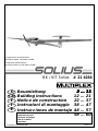 1
1
-
 2
2
-
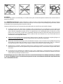 3
3
-
 4
4
-
 5
5
-
 6
6
-
 7
7
-
 8
8
-
 9
9
-
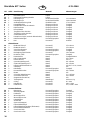 10
10
-
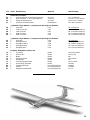 11
11
-
 12
12
-
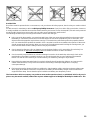 13
13
-
 14
14
-
 15
15
-
 16
16
-
 17
17
-
 18
18
-
 19
19
-
 20
20
-
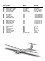 21
21
-
 22
22
-
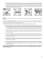 23
23
-
 24
24
-
 25
25
-
 26
26
-
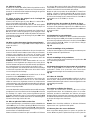 27
27
-
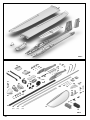 28
28
-
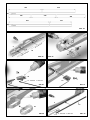 29
29
-
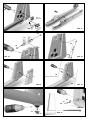 30
30
-
 31
31
-
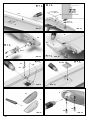 32
32
-
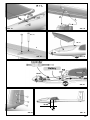 33
33
-
 34
34
-
 35
35
-
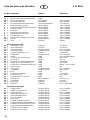 36
36
-
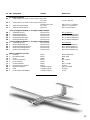 37
37
-
 38
38
-
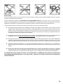 39
39
-
 40
40
-
 41
41
-
 42
42
-
 43
43
-
 44
44
-
 45
45
-
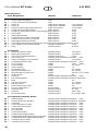 46
46
-
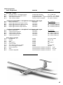 47
47
-
 48
48
-
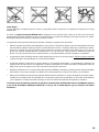 49
49
-
 50
50
-
 51
51
-
 52
52
-
 53
53
-
 54
54
-
 55
55
-
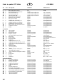 56
56
-
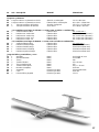 57
57
-
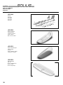 58
58
-
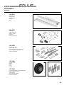 59
59
-
 60
60


MULTIPLEX Multiplex 21 4264 Le manuel du propriétaire
- Catégorie
- Jouets télécommandés
- Taper
- Le manuel du propriétaire
- Ce manuel convient également à
dans d''autres langues
Documents connexes
-
MULTIPLEX 2 Heron Le manuel du propriétaire
-
MULTIPLEX Funglider Le manuel du propriétaire
-
-
-
-
-
-
-
HiTEC Twinstar Nd Kit Rr Le manuel du propriétaire
-