Amprobe AMP-25 Manuel utilisateur
- Catégorie
- Mesure, test
- Taper
- Manuel utilisateur

AMP-25
ZERO
2 Sec
TRMS
AC /
AMP-25
Mini-Clamp
User Manual
ENG FRE
SPA


AMP-25
Mini-Clamp
User Manual
6/2018, 6004363 C
©2018 Amprobe
®
All rights reserved. Printed in Taiwan
English

Limited Warranty and Limitation of Liability
Your Amprobe product will be free from defects in material and workmanship for
one year from the date of purchase unless local laws require otherwise. This warranty
does not cover fuses, disposable batteries or damage from accident, neglect, misuse,
alteration, contamination, or abnormal conditions of operation or handling. Resellers
are not authorized to extend any other warranty on the behalf of Amprobe. To obtain
service during the warranty period, return the product with proof of purchase to an
authorized Amprobe Service Center or to an Amprobe dealer or distributor. See Repair
Section for details. THIS WARRANTY IS YOUR ONLY REMEDY. ALL OTHER WARRANTIES
- WHETHER EXPRESS, IMPLIED OR STATUTORY - INCLUDING IMPLIED WARRANTIES OF
FITNESS FOR A PARTICULAR PURPOSE OR MERCHANTABILITY, ARE HEREBY DISCLAIMED.
MANUFACTURER SHALL NOT BE LIABLE FOR ANY SPECIAL, INDIRECT, INCIDENTAL OR
CONSEQUENTIAL DAMAGES OR LOSSES, ARISING FROM ANY CAUSE OR THEORY. Since
some states or countries do not allow the exclusion or limitation of an implied warranty or
of incidental or consequential damages, this limitation of liability may not apply to you.
Repair
All Amprobe returned for warranty or non-warranty repair or for calibration should be
accompanied by the following: your name, company’s name, address, telephone number,
and proof of purchase. Additionally, please include a brief description of the problem or
the service requested and include the test leads with the meter. Non-warranty repair or
replacement charges should be remitted in the form of a check, a money order, credit
card with expiration date, or a purchase order made payable to Amprobe.
In-Warranty Repairs and Replacement – All Countries
Please read the warranty statement and check your battery before requesting repair.
During the warranty period, any defective test tool can be returned to your Amprobe
distributor for an exchange for the same or like product. Please check the “Where to
Buy” section on amprobe.com for a list of distributors near you. Additionally, in the
United States and Canada, in-warranty repair and replacement units can also be sent to
an Amprobe Service Center (see address below).
Non-warranty Repairs and Replacement – United States and Canada
Non-warranty repairs in the United States and Canada should be sent to an
Amprobe Service Center. Call Amprobe or inquire at your point of purchase for
current repair and replacement rates.
USA: Canada:
Amprobe Amprobe
Everett, WA 98203 Mississauga, ON L4Z 1X9
Tel: 877-AMPROBE (267-7623) Tel: 905-890-7600
Non-Warranty Repairs and Replacement – Europe
European non-warranty units can be replaced by your Beha-Amprobe distributor for a
nominal charge. Please check the “Where to Buy” section on beha-amprobe.com for a
list of distributors near you.
Beha-Amprobe
Division and reg. trademark of Fluke Corp. (USA)
Germany* United Kingdom The Netherlands - Headquarters**
In den Engematten 14 52 Hurricane Way Science Park Eindhoven 5110
79286 Glottertal Norwich, Norfolk 5692 EC Son
Germany NR6 6JB United Kingdom The Netherlands
Tel.: +49 (0) 7684 8009 - 0 Tel.: +44 (0) 1603 25 6662 Tel.: +31 (0) 40 267 51 00
beha-amprobe.de beha-amprobe.com beha-amprobe.com
*(Correspondence only – no repair or replacement available from this address.
European customers please contact your distributor.)
**single contact address in EEA Fluke Europe BV

1
AMP-25 Mini-Clamp
CONTENTS
SYMBOL ............................................................................... 3
SAFETY INFORMATION ....................................................... 4
UNPACKING AND INSPECTION ........................................... 6
MEASUREMENTS ................................................................. 6
Measuring AC and DC Current ...................................... 8
DC A ZERO....................................................................... 9
Low Pass Filter................................................................. 9
Inrush Current ................................................................. 9
Non-Contact Voltage Detection .................................... 10
Data Hold ....................................................................... 11
Auto Power Off .............................................................11
SPECIFICATIONS ................................................................... 12
ELECTRICAL SPECIFICATIONS ............................................. 14
MAINTENANCE AND REPAIR .............................................. 16
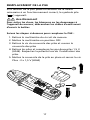
BATTERY REPLACEMENT ..................................................... 17

2
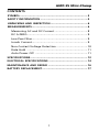
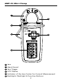
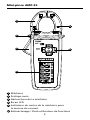
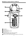
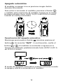
1
Jaw
2
Hand Guard
3
Jaw Trigger
4
LCD Display
5
Indicator of the Jaw Center for Current Measurement
6
Backlight / Flashlight & Function Buttons
AMP-25 Mini-Clamp
AMP-25
ZERO
2 Sec
TRMS
AC /
1
2
4
3
5
6

3
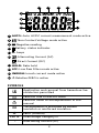
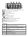
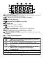
7
AUTO: Auto AC/DC current measurement mode active
8
Non-Contact Voltage mode active
9
Negative reading
10
Battery status indicator
11
A: Amps
12
Alternating Current (AC)
Direct Current (DC)
13
HOLD: Data hold
14
LPF: Low Pass Filter mode active
15
INRUSH: Inrush current mode active
16
∆ Relative ZERO is active
SYMBOLS
Application and removal from hazardous live
conductors permitted
Caution! Risk of electric shock
W
Caution! Refer to the explanation in this
manual
T
The equipment is protected by double
insulation or reinforced insulation
J
Earth (Ground)
CAT III Overvoltage Category lll
B
Alternating Current (AC)
13141516
7
8
9
11
12
10

4
F
Direct Current (DC)
Battery
)
Canadian Standards Association (NRTL/C)
P
Complies with European Directives
Conforms to relevant Australian standards
=
Do not dispose this product as unsorted
municipal waste. Contact aqualified recycler
SAFETY INFORMATION
The Meter complies with:
• UL/IEC/EN 61010-1, CAN/CSA C22.2 No. 61010-1-12,
Pollution Degree 2, Measurement Category III 600 V
• IEC/EN 61010-2-032, CAN/CSA-C22.2 No. 61010-2-032-12
• EMC IEC/EN 61326-1
Measurement Category III (CAT III) refers to measurements
of hard-wired equipment in fixed installations, distribution
boards, and circuit breakers. Also includes cables, bus
bars, junction boxes, switches, socket outlets in the fixed
installation, and stationary motors with permanent
connections to fixed installations.
CENELEC Directives
The instruments conform to CENELEC Low-voltage
directive 2006/95/EC and Electromagnetic compatibility
directive 2004/108/EC.
W Warning: Read Before Using
To avoid possible electric shock or personal injury:
• Use the Meter only as specified in this manual or the
protection provided by the Meter might be impaired.
• Avoid working alone so assistance can be rendered.
• Do not use the Meter in wet or dirty environments.

5
• Do not use the Meter if it appears damaged. Inspect
the Meter before use. Look for cracks or missing
plastic. Pay particular attention to the insulation
around the connectors.
• Have the Meter serviced only by qualified service
personnel.
• Use extreme caution when working around bare
conductors or bus bars. Contact with the conductor
could result in electric shock.
• Do not hold the Meter anywhere beyond the tactile
barrier.
• When measuring current, center the conductor in the
clamp.
• Never operate the Meter with the battery cover
removed or the case open.
• Never remove the battery cover or open the case of
the Meter without first removing the jaws from a live
conductor.
• Use caution when working with voltages above 30 V
AC rms, 42 V AC peak, or 60 V DC. These voltages pose
a shock hazard.
• Do not attempt to measure any voltage that might
exceed the maximum range of the Meter.
• Use the proper function for your measurements.
• Do not operate the Meter around explosive gas,
vapor, or dust.
• Use only 1.5 V LR44 batteries, properly installed in the
Meter case, to power the Meter.
• To avoid false readings that can lead to electrical
shock and injury, replace the battery as soon as the
low battery indicator (
) appears. Check Meter
operation on a known source before and after use.
• When servicing, use only specified replacement parts.
• Adhere to local and national safety codes. Individual
protective equipment must be used to prevent shock
and arc blast injury where hazardous live conductors
are exposed.

6
UNPACKING AND INSPECTION
Your shipping carton should include:
1 Clamp meter
2 1.5 V LR44 batteries
1 Carrying case
1 User Manual
If any of these items are damaged or missing, return
the complete package to the place of purchase for an
exchange.
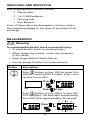
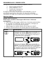
MEASUREMENTS
W Warning
To avoid possible electric shock or personal injury:
• To avoid electric shock or personal injury:
• When measuring current, center the conductor
in the clamp.
• Keep fingers behind Tactile Barrier.
• Use the proper function for measurements.
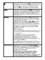
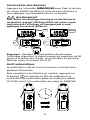
Button Description
Press button to turn ON the meter (the
default is auto AC/DC A mode). Press > one
second to turn OFF.
Press
Press
OFF
>1 Sec
Press button to turn ON or to turn OFF
LCD backlight. The backlight automatically
turns OFF after approximately 30 seconds.
Press

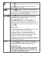
7
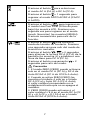
Press button to select AC A or DC A mode.
Press
button > one second to return to
AUTO AC/DC A mode.
Press button to enter Low Pass Filter
mode (LPF is displayed). Press a second time
to enter Inrush mode (INRUSH is displayed).
Press again to exit the function.
/
Press button to activate non-contact
voltage mode. Press a second time to exit
non-contact voltage mode.
Press / button > two seconds to
clear DC A reading from the display (
∆ is
displayed) and establish a baseline for DC A.
Press
button > two seconds again to exit
this mode.
W
Caution
1. ZERO mode can be activated in DC A and
DC A of Auto DC/AC A mode only.
2. When ZERO is activated (symbol
∆ is
displayed in DC A and Auto DC A mode
only), the offset residual value will not be
reset until the Meter is turned OFF.
3. ZERO can be activated if residual value < 6
A in DC A mode, < 6 A DC and <0.1 A AC in
Auto DC/AC A mode.
HOLD Press HOLD button to freeze the display
reading (HOLD is displayed) and releases the
reading when pressed a second time.
W Warning
To avoid possible electric shock or personal
injury, when Display HOLD is activated, be
aware that the display will not change when
you apply a different current.

8
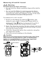
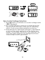
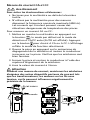
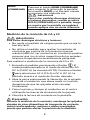
Measuring AC and DC Current
W Warning
To avoid electrical shock and injury:
• Do not hold the Meter anywhere beyond the tactile
barrier.
• Do not use the Meter to measure currents above
the maximum rated frequency (400Hz). Circulating
currents may cause the magnetic circuits of the Jaws
reach hazardous excessive temperatures.
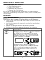
To measure AC or DC current:
1. Switch on the Meter by pressing
button, the
default is auto AC/DC A detection mode (AUTO is
displayed). Press
button to choose AC A or DC A.
The display reflects the chosen function mode.
2. Open the clamp by pressing the jaw release and insert
the conductor to be measured into the clamp. Ensure
the jaws are firmly closed.
3. Close the clamp and center the conductor using the
jaw alignment marks.
4. View the current reading on the display.
W Caution
During current measurement keep the jaws away from
other current carrying devices such as transformers,
motors or energized wires, as they may negatively
influence accuracy of the measurement.
Auto
Press > 1 Sec
Press
Press
WCAT III 600 V
Tactile barrier

9
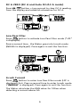
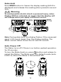
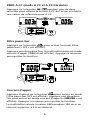
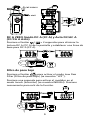
DC A ZERO (DC A and Auto DC/AC A mode)
Press / button > two second to clear DC A reading
from the display and establish a baseline for DC A.
0A
Low Pass Filter
Press button to activate Low Pass Filter mode (“LPF”
is displayed).
Press a second time , the Meter goes into Inrush mode
(INRUSH is displayed). Press again to exit the function.
LPF
Press
100A/1KHz
Inrush Current
Press button to enter Low Pass Filter mode (LPF is
displayed) first. Press a second time to enter Inrush mode
(“INRUSH” is displayed). Press again to exit the function.
The Meter calculates the RMS value for 100ms when
detecting a current above 5A.

10
INRUSH
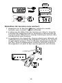
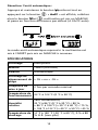
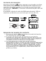
Non-Contact Voltage Detection
1. Press button to activate non-contact voltage mode
( is displayed).
2. The voltage detection antenna is located along the
top end of the stationary clamp jaw for detecting
electric field surrounding energized conductors
3. Detected electric field signal strength is indicated by
a series of bar-graph segments on the display and
beeper. The stronger the electric field detected, the
more bar-graph segments are displayed and more
intense beep-sound is generated.

11
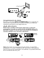
Data Hold
Press HOLD button to freeze the display reading (HOLD is
displayed) and releases the reading when pressed a second
time.
W Warning
To avoid possible electric shock or personal injury, when
Display HOLD is activated, be aware that the display will
not change when you apply a different current.
HOLD
0A
Press
HOLD
DC 100A
HOLD
Note: During data hold, the display flashes if the measured
signal is 50 counts larger than the display reading. The
Meter cannot detect across the AC and DC current.
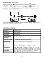
Auto Power Off
The Meter turns off if there is no button pushed operation
for 20 minutes.
To turn the Meter back on, press
button and release to
restart the Meter. The Meter goes into default mode (auto
AC/DC A) when the Meter is turned back ON.

12
Disable auto power off:
Press and hold
button while pressing button.
“RoFF” is displayed, then release
and button. The
meter is turned ON and goes into default measurement
function (auto AC/DC A).
The auto power off mode resumes back when the Meter is
OFF and is turned ON again.
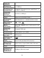
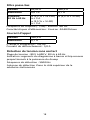
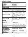
SPECIFICATIONS
Display 6000 counts
Sensing True-RMS
Polarity Automatic
Over-Range
Display
“OL” or “-OL”
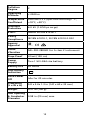
Update Rate 2 times per second nominal
Operating
Temperature
32 °F to 122 °F (0 °C to 50 °C)
Relative
Humidity
Non-condensing,
32 °F to 86 °F (0 °C to 30 °C) ≤ 80%,
>86 °F to 104 °F (>30 °C to 40 °C) ≤ 75%,
>104 °F to 122 °F (>40 °C to 50 °C) ≤ 45%
Storage
Temperature
-4 °F to 140 °F (-20 °C to 60 °C), 0% to
80% R.H. (with battery removed)

13
Pollution
Degree
2
Operating
Altitude
≤ 2000 m
Temperature
Coefficient
nominal 0.2 x (specified accuracy)/ °C ,
<18°C, >28°C)
Transient
Protection
6.0 kV (1.2/50 µs surge)
E.M.C. Meets IEC/EN 61326-1
Safety
Compliance
IEC/EN 61010-1, IEC/EN 61010-2-032
Agency
Approval
)
P
Shock
Vibration
MIL-PRF-28800F for A class 2 instrument
Drop-Proof 4 feet (120 cm)
Power
Supply
Two 1.5V LR44 size battery
Battery Life 20 hours
Low Battery
Indication
Auto Power
Off
Idle for 20 minutes
Dimension
(L x W x H)
5.8 x 2.4x 1.3 in (147 x 60 x 32 mm)
Weight 0.31 lb (140 g)
Jaw Opening
& Conductor
Diameter
0.98 in (25 mm) max.

14
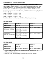
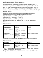
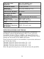
ELECTRICAL SPECIFICATIONS
Accuracy is given as ±(% of reading + counts of least
significant digit) at 23°C ± 5°C,with relative humidity less
than 80% R.H., AC A specifications are ac coupled, true
R.M.S. The crest factor may be up to 3.0 as 4000 counts.
For non-sinusoidal waveforms, additional accuracy by Crest
Factor (C.F.):
Add 3.0% for C.F. 1.0 ~ 2.0
Add 5.0% for C.F. 2.0 ~ 2.5
Add 7.0% for C.F. 2.5 ~ 3.0
Position Error of Clamp: ±1.5% of display reading
AC Current
Range 60.00 A 300.0 A
Resolution 0.01 A 0.1 A
Accuracy
50 Hz to 100 Hz
± (1.5 % + 25 LSD)
at < 3 A
± (1.5 % + 5 LSD)
at ≥ 3 A
± (1.5 % + 5 LSD)
Accuracy
100 Hz to 400 Hz
± (2.5 % + 25 LSD)
at < 3 A
± (2.5 % + 5 LSD)
at ≥ 3 A
± (2.5 % + 5 LSD)
Frequency Response: 50 to 400Hz (Sine Wave)
DC Current
Range 60.00 A
1)
300.0 A
Resolution 0.01 A 0.1 A
Accuracy ± (1.5 % + 10 LSD)
2)
± (1.5 % + 5 LSD)
1)
There are less than 0.3A variations as measuring in
different directions.
2)
Add 10 LSD to accuracy in Auto AC / DC A mode.

15
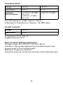
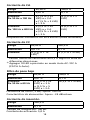
Low Pass Filter
Range 60.00 A 300.0 A
Resolution 0.01 A 0.1 A
Accuracy
50 Hz to 60 Hz
± ( 3.5 % + 25 LSD)
at < 3 A
± (3.5 % + 5 LSD)
at ≥ 3 A
± (3.5 % + 5 LSD)
Cut-off Frequency (-3dB): Approx. 160 Hz
Attenuation Characteristic: Approx. -24 dB/Octave
Inrush Current
Range 300.0 A
Resolution 0.1 A
CIntegration Time: 100 ms
Trigger Current: 5.0 A
Non-Contact Voltage Detection
Voltage range: 80 V to 600 V, 50 Hz to 60 Hz
Indication: bar-graph segments and audible beep tones
proportional to the field strength
Detection frequency: 50/60 Hz
Detection antenna: inside the top side of the stationary jaw

16
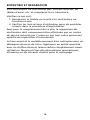
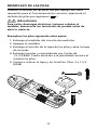
MAINTENANCE AND REPAIR
If the Meter fails to operate, check battery, test leads, etc.,
and replace as necessary.
Double check the following:
1. Replace the fuse or battery if the meter does not
work.
2. Review the operating instructions for possible
mistakes in operating procedure.
Except for the replacement of the battery, repair of the
meter should be performed only by a Factory Authorized
Service Center or by other qualified instrument service
personnel.
The front panel and case can be cleaned with a mild
solution of detergent and water. Apply sparingly with a
soft cloth and allow to dry completely before using. Do
not use aromatic hydrocarbons, gasoline or chlorinated
solvents for cleaning.
La page charge ...
La page charge ...
La page charge ...
La page charge ...
La page charge ...
La page charge ...
La page charge ...
La page charge ...
La page charge ...
La page charge ...
La page charge ...
La page charge ...
La page charge ...
La page charge ...
La page charge ...
La page charge ...
La page charge ...
La page charge ...
La page charge ...
La page charge ...
La page charge ...
La page charge ...
La page charge ...
La page charge ...
La page charge ...
La page charge ...
La page charge ...
La page charge ...
La page charge ...
La page charge ...
La page charge ...
La page charge ...
La page charge ...
La page charge ...
La page charge ...
La page charge ...
La page charge ...
La page charge ...
La page charge ...
La page charge ...
La page charge ...
La page charge ...
-
 1
1
-
 2
2
-
 3
3
-
 4
4
-
 5
5
-
 6
6
-
 7
7
-
 8
8
-
 9
9
-
 10
10
-
 11
11
-
 12
12
-
 13
13
-
 14
14
-
 15
15
-
 16
16
-
 17
17
-
 18
18
-
 19
19
-
 20
20
-
 21
21
-
 22
22
-
 23
23
-
 24
24
-
 25
25
-
 26
26
-
 27
27
-
 28
28
-
 29
29
-
 30
30
-
 31
31
-
 32
32
-
 33
33
-
 34
34
-
 35
35
-
 36
36
-
 37
37
-
 38
38
-
 39
39
-
 40
40
-
 41
41
-
 42
42
-
 43
43
-
 44
44
-
 45
45
-
 46
46
-
 47
47
-
 48
48
-
 49
49
-
 50
50
-
 51
51
-
 52
52
-
 53
53
-
 54
54
-
 55
55
-
 56
56
-
 57
57
-
 58
58
-
 59
59
-
 60
60
-
 61
61
-
 62
62


Amprobe AMP-25 Manuel utilisateur
- Catégorie
- Mesure, test
- Taper
- Manuel utilisateur
dans d''autres langues
- English: Amprobe AMP-25 User manual
- español: Amprobe AMP-25 Manual de usuario
Documents connexes
-
Amprobe Digital Multimeter AM-420 Manuel utilisateur
-
Amprobe AM-520& AM-530 Multimeter Manuel utilisateur
-
-
Amprobe ALC-110 Leakage Clamp Manuel utilisateur
-
-
Amprobe ACDC-400 Manuel utilisateur
-
-
-
-