Topcon MC-i3 Installation And Setup Manual
- Taper
- Installation And Setup Manual

MC-i3
1000082-06: MC-I3 Dig UHF II W/ Modem, BT, & Single GPS
1000082-07: MC-I3 Dig UHF II W/ Modem, BT, & Dual GPS
1000082-08: MC-I3 FH915+ W/ Modem, BT, Single GPS
1000082-09: MC-I3 FH915+ W/ Modem, BT, Dual GPS
INSTALLATION AND
SETUP GUIDE

INTRODUCTION
The MC-i3 comes in a number of different configurations. This manual covers MC-i3’s that contain
DUHF2 or FH915+ modems. These units can be purchased as part of a machine control kit which may
contain:
1000082-XX: MC-i3
o 1000082-06: Assy, MC-I3 Dig UHF II W/ Modem, BT, & Single GPS
o 1000082-07: Assy, MC-I3 Dig UHF II W/ Modem, BT, & Dual GPS
o 1000082-08: Assy, MC-I3 FH915+ W/ Modem, BT, Single GPS
o 1000082-09: Assy, MC-I3 FH915+ W/ Modem, BT, Dual GPS
1000220-01: SL-100 MAG MOUNT KIT
Control Box
o 9169-0000: GX60
o 1001946-01: GX-30
Antenna:
o 9050-01: ANTENNA CONFIG KIT, 915 SS
o 9050-02: ANTENNA CONFIG KIT, 410-430 DIGITAL UHF
o 9050-03: ANTENNA, CONFIG KIT, 430-450 DIGITAL UHF
o 9050-04: ANTENNA CONFIG KIT, 450-470 DIGITAL UHF
o 9050-18: ANTENNA CONFIG SL-R3 KIT
CABLES
o 1000630-01: MC-i3 to GX60 Cable (Same cable for GX-30)
o 1001269-01: SL-100-MC-I3 Program Cable (Power-Serial)
o 1001270-01: SL-100-MC-I3 Program Cable (Ethernet)
3DMC Password
o 3DMC Standard
o 3DMC Standard + sitelink3D
o 3DMC Standard + sitelink3D Advance
Optional Items
o TNC to N-Type GPS cable adaptors
o SIM Card (SIM APN, Username, Password)
MC-i3 LED Status
Power LED:
Solid Green: Status On
On Light: Status Off
Transmit LED:
Flashing Green: Receive Mode
Solid Green: Link to Base Station Radio Established
Solid Green with Red Flash: Receiving Data
Bluetooth LED:
No Light: Bluetooth not enabled
Blinking Blue: Bluetooth Enabled
Solid Blue: Bluetooth Connected

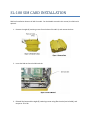
SL-100 SIM CARD INSTALLATION
SIM Card installation relates to all MC-i3 models. For the Models covered in this manual, the SIM card is
optional.
1. Remove the eight (8) retaining screws from the base of the MC-i3, and remove the base
2. Insert the SIM card into the SIM card slot
3. Reinstall the base and the eight (8) retaining screws using Blue Loctite (not included), and
torque to 12 in‐lbs.

MC-i3 MODELS WITH DUHF2 or FH915+:
CONFIGURATION
This section relates to the following MC-i3 Models
1000082-06: Assy, MC-I3 Dig UHF II W/ Modem, BT, & Single GPS
1000082-07: Assy, MC-I3 Dig UHF II W/ Modem, BT, & Dual GPS
1000082-08: Assy, MC-I3 FH915+ W/ Modem, BT, Single GPS
1000082-09: Assy, MC-I3 FH915+ W/ Modem, BT, Dual GPS
MC-i3 Connectivity
MC-i3’s with a single GPS board connects:
• DUHF2/FH915+ Radio to GPS Port B
• Bluetooth to GPS Port C
• GPS Port A to MC-i3 External Serial Port 1
• GPS Port D to MC-i3 External Serial Port 2
MC-i3’s with two GPS’s boards connect:
• DUHF2/FH915+ radio to GPS(Main) Port B and GPS (Aux) Port B (RX Only)
• Bluetooth to GPS(Main) Port C
• GPS (Main) Port A to MC-i3 External Serial Port 1
• GPS (Aux) Port A to MC-i3 External Serial Port 2
• GPS (Main) Port D to GPS (Aux) Port D
Topcon Receiver Utility (TRU)
TRU V2.7 or later should be used when working with a MC-i3. TRU can be used set the GPS Serial
Number ID, Bluetooth configuration, and to load and configure Radio Firmware
GPS Serial Number ID
The GPS serial number ID will come preset to MC-i3 xxx-xxxxx, where xxx-xxxxx is the serial number of
the MC-i3 unit. It is important for the GPS serial number to be correctly set or there will be some
functionality that will not work in TRU.
If the GPS serial number ID is not set in each of the GPS boards in the MC-i3, it can be set using TRU.
Connect in receiver managing mode -> Information. Click on the Cog icon at the bottom of the receiver
Info window, and enter in the MC-i3 Serial number and press OK to save it

Bluetooth
It is possible to connect to the MC-i3 using Bluetooth. Bluetooth is connected to Port C of the Main GPS
board. Bluetooth should be configured correctly from the factory.
If the Bluetooth ID and Pin need are not correctly set, they can be configured using TRU. Connect in
receiver managing mode -> Receiver Settings -> Bluetooth. By default the Bluetooth name should be
MC-i3 xxx-xxxxx, where xxx-xxxxx is the serial number of the MC-i3 unit
Modem Script Files
To be able to use the cellular modems on the DUHF II and FH915 boards, The relevant script file needs
to be loaded into the GPS board.
The Modem Script file can be loaded using TRU 2.7 or later. Connect in receiver managing mode ->
Modem Driver. Follow the prompts if no script file is loaded, or Right click and select scan for hardware
changes if you wish to upgrade an existing modem profile
Radio (DUHF2/FH915+)
Radio Firmware can be loaded using TRU. Connect using TRU in Application Mode: Firmware loading.
Select the Firmware Loader Icon
The radio can be configured using TRU. Connect using TRU in Application Mode: Modem Managing.
The radio is on Port B. Select Settings, then on the Settings tab choose the required settings. Press the
Red “write the settings to the modem” button, so the settings are held.
3DMC Configuration
The 3DMC configuration will be different for each machine type; however the machine configuration is
accessed by selecting the Topcon Logo -> Control -> Machine setup. From the Machine files page select
New to create a new machine or select an existing machine and press edit to edit the machine.
3DMC V11.0 Machine Setup:
• Options Page (second page of Machine Setup Wizard): Select Position Input: Custom so that
the GPS Coms Configuration screen gets displayed in the setup Wizard.
• GPS Comms Configuration Page: Set Connection Type to Serial Port, and the Com Port to COM1
(GX-60 or GX-30)
• GPS radio configuration UHF/SS:
o For Digital UHF 2 (UHF) select Radio Type: Topcon Digital 2 (UHF); Connected to: Serial
Port B; Baud Rate: 38400; and the required Format:
o For FH915+ (Spread Spectrum) select Radio Type: Topcon FH915 (SS); Connected to:
Serial Port B; Baud Rate: 38400; and the required Format:

• GPS Network Corrections
o For Network corrections the cellular modem attached to the radio board is used to
establish an internet connection to the NTRIP (Topnet) server.
o When using a FH915+ select Radio Type: Topcon FH915 (HSPA);
o When using a Digital UHF 2 select Radio Type: Topcon Digital 2 (GPRS);
o Connected to: Serial Port B; Baud Rate: 38400. The Format will be automatically set
when a mount point is selected.
o Use the Set button to enter the NTRIP servers IP address and password\
o GPRS button -> Network Tab: Enter the SIM Card APN/Username/Password. The Dial
number is *99***1# and the SIM Pin is 0000.
o GPRS Button -> NTRIP Tab: Enter the NTRIP Servers Username/Password. The Network
type for a Topnet server is VRS. The mount points are not selected at this point.
• Once the machine is set up, exit to the main screen and 3DMC will establish a connection to the
GPS. Once the connection is established 3DMC will establish a network connection. At this
point the NTRIP mount points need to be downloaded from the NTRIP server. Go to Topcon
Icon -> Tools -> Configure Radios. Select the NTRIP Tab and press the spanner besides the
Mount-point dropdown Box to download mount points. Once the mount-points are
downloaded, select the mount-point that you wish to work with. The GPS should now get a
fixed solution.
Sitelink3D: A Sitelink3D connection is not possible using a MC-i3 with DUHF2/FH915 radio board.

Safety Warnings
RF Radiation Hazard Warning
To ensure compliance with FCC and Industry Canada RF exposure requirements, this device must be installed in a
location where the antennas of the device will have a minimum distance of at least 20 cm from all persons. Using
higher gain antennas and types of antennas not certified for use with this product is not allowed.
Installez l'appareil en veillant à conserver une distance d'au moins 20 cm entre les éléments rayonnants et les
personnes. Cet avertissement de sécurité est conforme aux limites d'exposition définies par la norme CNR-102 at
relative aux fréquences radio.
Regulatory Information
FCC statements
This equipment has been tested and found to comply with the limits for a Class B digital device pursuant to part 15
of the FCC rules. These limits are designed to provide reasonable protection against harmful interference when the
equipment is operated in a commercial environment. This equipment generates, uses, and can radiate radio
frequency energy and, if not installed and used in accordance with the instruction manual, may cause harmful
interference to radio communications. Operation of this equipment in a residential area is likely to cause harmful
interference in which case the user will be required to correct the interference at his own expense. If this
equipment does cause interference to radio or television equipment reception, which can be determined by
turning the equipment off and on, the user is encouraged to try to correct the interference by one or more of the
following measures:
1) Reorient or relocate the receiving antenna.
2) Move the equipment away from the receiver.
3) Plug the equipment into an outlet on a circuit different from that to which the receiver is powered.
4) Consult the dealer or an experienced radio/television technician for additional suggestions.
IC statements
This Class B digital apparatus complies with Canadian ICES-003.
This device complies with Industry Canada licence-exempt RSS standard(s). Operation is subject to the
following two conditions: (1) this device may not cause interference, and (2) this device must accept any
interference,including interference that may cause undesired operation of the device.

Déclaration de conformité IC :
Cet appareil numérique de la classe B est conforme à la norme RSS-GEN du Canada
Ce matériel respecte les standards RSS 210 exempt de licence d’Industrie Canada. Son utilisation est soumise aux
deux conditions suivantes :
(1) l’appareil ne doit causer aucune interférence, et
(2) l’appareil doit accepter toute interférence, quelle qu’elle soit, y compris les interférences
susceptibles d’entraîner un fonctionnement non requis de l’appareil.
IC RF Radiation Exposure Statement
When installing, locate or point this device away from the installer, so it does not emit RF field in excess of Health
Canada’s limits for the general population; Consult Safety Code 6 from Heath Canada’s website at
www.hc‐sc.gc.ca/rpb.
IC Additional Statement with Detachable Antennas
Under Industry Canada regulations, this radio transmitter may only operate using an antenna of a type and
maximum (or lesser) gain approved for the transmitter by Industry Canada. To reduce potential radio interference
to other users, the antenna type and its gain should be so chosen that the equivalent isotropically radiated power
(e.i.r.p.) is not more than that necessary for successful communication.
Conformément à la réglementation d'Industrie Canada, le présent émetteur radio peut fonctionner avec une
antenne d'un type et d'un gain maximal (ou inférieur) approuvé pour l'émetteur par Industrie Canada. Dans le but
de réduire les risques de brouillage radioélectrique à l'intention des autres utilisateurs, il faut choisir le type
d'antenne et son gain de sorte que la puissance isotrope rayonnée équivalente (p.i.r.e.) ne dépasse pas l'intensité
nécessaire à l'établissement d'une communication satisfaisante.
The device (with FH915 modem) has been designated to operate with the antennas listed below and have a
maximum gain of 2.1dBi. Antennas not included in this or having a gain greater than 2.1dBi are strictly prohibited
for use with this device. The required antenna impedance is 50 ohms.
MC-i3 FH915 2.1 dBi Dipole Antenna
Manufacture/Type
890‐960 MHz LARSEN SPDA17RP918
Connect Type: TNC male reverse polarity
Manufacture /Type
902-928 Mhz Nearson S467XX-915S
Connect Type: TNC male reverse polarity

Topcon Positioning Systems,
Inc.
7400 National Drive, Livermore, CA 94550
800∙443.4567 www.topconpositioning.com
ISO 9001:2000
FM
68448
MC-i3 DUHF2-FH915 Installation and Setup Guide
P/N: xxxxxxx-xx
©2012 Topcon Positioning Systems, Inc. All rights reserved. No unauthorized duplication.
-
 1
1
-
 2
2
-
 3
3
-
 4
4
-
 5
5
-
 6
6
-
 7
7
-
 8
8
-
 9
9


Topcon MC-i3 Installation And Setup Manual
- Taper
- Installation And Setup Manual
dans d''autres langues
- English: Topcon MC-i3
Documents connexes
Autres documents
-
Eurotech DynaGATE 10-12 Le manuel du propriétaire
-
Eurotech ReliaGATE 10-12 Le manuel du propriétaire
-
-
-
-
-
-