Intermec MobileLAN access WA22 Mode d'emploi
- Taper
- Mode d'emploi

b Route power cables from the outside of the enclosure, through the small cord
connector, through the small hole in the enclosure, and then through the
small cord connector ring. You may need to cut the rubber stopper to make
it easier to thread the cable.
c (Power bridge mounting kit) Use an Ethernet cable to connect the access
point to the power bridge Data In port.
d (Power bridge mounting kit) Connect the power bridge to power. You can
use the terminal block on the power bridge mounting plate.
e (Heater/fan kit) Connect the heater or fan assembly plate to power.
• Route the line wire (black) to the thermostat.
• Route the neutral wire with the other neutral (white) wire to the terminal
block.
• Route the ground wire (green) to the ground lug.
7 Route the Ethernet cable from the access point or power bridge through the
small cord connector ring, through one of the smaller holes in the enclosure,
and then through the rest of the small cord connector. You may need to cut the
rubber stopper to make it easier to thread the cable.
8 Route the antenna cables. Intermec recommends that you insert each antenna
cable through a separate large cord connector.
a Drill out one of the large round indentations on the bottom of the enclosure
for each antenna cable. Two holes are already available.
b Route the antenna cable through the large cord connector, the enclosure slot,
and the access point. You may need to cut the rubber stopper to make it
easier to thread the antenna cable.
9 Using appropriate mounting hardware, mount the environmental enclosure to a
wall. The enclosure can weigh up to 6.4 kg (14 lbs).
Operating Temperature
WA22 in enclosure
-20°C to 40°C (-4°F to 104°F)
WA22 in enclosure with heater kit
-40°C to 40°C (-40°F to 104°F)
WA22 in enclosure with fan kit
-20°C to 60°C (-4°F to 140°F)
6001 36th Avenue West
Everett, WA 98203
U.S.A.
www.intermec.com
© 2003 Intermec Technologies Corp.
All Rights Reserved
MobileLAN access WA22 Environmental Enclosure Instructions
*073788-001*
*073788-001*
MobileLAN access WA22 Environmental Enclosure Instructions
Observe all electrical codes when installing the access point in the
environmental enclosure.
Attention: Respecter tous les codes de l’électricité lors de l’installation
du point d’accès dans le boîtier résistant aux conditions ambiantes.
Note: Intermec recommends that you use an experienced electrician to
install the environmental enclosure when you are using the power bridge
mounting kit, heater kit, or fan kit.
These instructions explain how to install the MobileLAN access WA22 in the
environmental enclosure and how to prepare the enclosure for installation. You
have one of these environmental enclosures:
• Environmental enclosure, opaque cover (P/N 073515)
• Environmental enclosure, clear cover (P/N 073488)
Top
Both enclosures come with an access point mounting bracket (pre-installed), two
large cord connectors, and one small cord connector. You may have also ordered
one of these accessory kits:
• Single-port power bridge mounting kit (P/N 073492)
• Heater kit, 120V (P/N 073489) or 120V/240V (P/N 073738)
• Fan kit, 120V (P/N 073594) or 230V (P/N 073640)
• Fan vent kit (P/N 063886)
1
• Antenna cable assembly, TNC plug/receptacle, 15 in. (P/N 073517)
• Large Hubbell cord connector (P/N 073487)
1
If you use the fan kit, you are not required to also use the fan vent kit. At elevated temperatures, the fan provides enough air circulation inside
the enclosure to keep the WA22 within safe operating temperatures.

To install the environmental enclosure
1 (Power bridge mounting kit) Install the power bridge in the enclosure.
a Remove the access point mounting plate from the enclosure.
b Use two screws to attach the power bridge mounting strap and the power
bridge to the power bridge mounting plate.
c Use three screws to secure the top two corners and the lower right corner of
the power bridge mounting plate to the enclosure.
d Use a fourth screw to secure a ground strap and the lower left corner of the
power bridge mounting plate to the enclosure.
2 Reinsert the access point mounting plate.
a Use two screws to secure the top right corner and the lower right corner of
the access point mounting plate to the enclosure.
b (Power bridge mounting kit) Use another screw to secure the other end of
the ground strap (from Step 1d) and top left corner the access point
mounting bracket to the enclosure.
c (Heater/fan kit) Use another screw to secure a ground strap and the lower left
corner of the access point mounting bracket to the enclosure.
If you do not have a power bridge mounting kit or a heater/fan kit, use two
screws to secure the left two corners of the access point mounting plate to the
enclosure.
3 On the WA22, insert one shoulder screw into each of the brass inserts and
tighten securely.
4 Insert the WA22 (upside-down) in its mounting bracket by inserting the
shoulder screws into the keyhole slots in the bracket. Slide the WA22 down
until it is firmly seated in the bracket.
5 (Heater/fan kit) Install the heater/fan assembly in the enclosure.
a Use a screw to secure the other end of the ground strap (from Step 2c) and
the top right corner of heater/fan assembly to the enclosure.
b Use three screws to secure other corners of the heater/fan assembly to the
enclosure.
c Adjust the thermostat to the temperature at which the heater or fan should
turn on.
Heater: -10°C (14°F)
Fan: 40°C (104°F)
d (Fan vent kit) Install the fan vents. If you choose to use fan vents, Intermec
recommends that you install two of them: one on one side near the bottom
of the enclosure and one on the other side near the top. For help, see the
instructions that are included with your fan vent kit.
6 (Power bridge mounting kit or heater/fan kit) Route the power cables. Intermec
recommends that you separate the Ethernet cables and the power cables.
a Drill out the other small round indentation for the power cable.
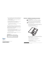
WA2 2
Access point
mounting plate
Power bridge
mounting strap
Single port
power bridge
Terminal
block
Ground
Power bridge
mounting plate
Heater assembly
(shown)
or
Fan assembly
(not shown)
Cord
connector
ring
Small cord
connector (0.5 in)
Large cord
connector (0.75 in)
Neutral
m5 x 10mm
Screws (4)
6-32 x .375 in
Screws (2 )
Screws (4)
m5 x 10mm
Ground
Line
voltage
Ground
strap
Thermostat
Ground
strap
Ground
strap
Ground
strap
m5 x 10mm
Screws (4)
-
 1
1
-
 2
2


Intermec MobileLAN access WA22 Mode d'emploi
- Taper
- Mode d'emploi
dans d''autres langues
Documents connexes
-
Intermec MobileLAN access WA22 Guide de démarrage rapide
-
-
Intermec MobileLAN access Manuel utilisateur
-
Intermec MaxiScan 2100 Mounting & Installation
-
Intermec MobileLAN access 2102 Guide de démarrage rapide
-
-
-
-
-