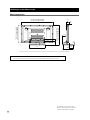
Pioneer PDK-TS05 Le manuel du propriétaire
- Taper
- Le manuel du propriétaire


3
Ja
1
2 3
Operating instructions
Mode d’emploi
Bedienungsanleitung
Istruzioni per l’uso
Gebruiksaanwijzing
Manual de instrucciones
Table top stand
Support de couverture de table
Tischständer
Supporto di tavolo
Tafelbladstaander
Soporte de mesa
PDK-TS05

4
Ja
1

5
Ja
2 1
1
3

6
Ja
1
2 2
3 3
4
5
2
2
3

7
Ja
1
2
3
4
2˚
2˚

8
Ja
10˚
10˚
2˚
2˚

9
Ja
1
2
3
4

10
Ja
1
2
1
2
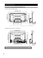
120
575 PDP-505HDL / PDP-505HDS
500 PDP-435HDL / PDP-435HDS
554 PDP-435SX
575 PDP-505HDL / PDP-505HDS
500 PDP-435HDL / PDP-435HDS
554 PDP-435SX
24
356

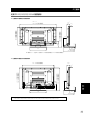
11
Ja
1
2
3
4
5
6
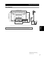
577
143 80
814 (PDP-505HDL)
729 (PDP-435HDL)
380
162
93
23
1500 (PDP-505HDL
) *
1
1462 (PDP-505HDL ) *
2
1350 (PDP-435HDL ) *
1
1312 (PDP-435HDL ) *
2
737 (PDP-505HDL)
652 (PDP-435HDL)
18.5
125

12
Ja
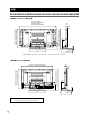
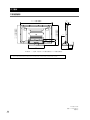
577
143 80
814 (PDP-505HDS/504HD/504HDV)
729 (PDP-435HDS/434HD/434HDV)
380
157*
2
162*
1
100*
1
98*
2
1438 (PDP-505HDS)
1440 (PDP-504HD/504HDV)
1288 (PDP-435HDS)
1290 (PDP-434HD/434HDV)
737 (PDP-505HDS/504HD/504HDV)
652 (PDP-435HDS/434HD/434HDV)
18.5
125
23*
1
28*
2
239
910 (PDP-505HDS/504HD/504HDV)
825 (PDP-435HDS/434HD/434HDV)
1270 (PDP-505HDS/504HD/504HDV)
1120 (PDP-435HDS/434HD/434HDV)
833 (PDP-505HDS/504HD/504HDV)
748 (PDP-435HDS/434HD/434HDV)
577
80
380
162*
1
157*
2
18.5
125
100*
1
98*
2
23*
1
28*
2

13
Ja
737 (PDP-505HDL/505HDS/504HD/504HDV)
652 (PDP-435HDL/435HDS/434HD/434HDV)
577
1270 (PDP-505HDL/505HDS/504HD/504HDV)
1120 (PDP-435HDL/435HDS/434HD/434HDV)
143 80
814 (PDP-505HDL/505HDS/504HD/504HDV)
729 (PDP-435HDL/435HDS/434HD/434HDV)
380
162*
1
157*
2
18.5
125
93*
1
98*
2
23*
1
28*
2
753
577
80
380
239
825
1168
162*
1
155*
2
93*
1
92*
2
26
123
18.5
94

14
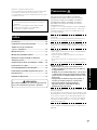
En
Thank you for buying Pioneer’s product.
Please read through the Operating Instructions to learn how
to operate your model safely and properly.
Please be advised to keep the Operating Instructions in
your place for future reference.
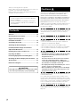
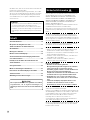
Contents
Cautions ................................................................. 14
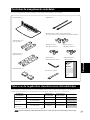
Checking the Enclosed Parts................................ 15
Support Columns/Spacers
Used/Not Used Table ........................................... 15
Assembling the Stand .......................................... 16
Attaching the Plasma Display .............................. 17
Forward/Backward Angle of Inclination
Adjustment Mechanism ....................................... 18
Installing the Product on a Rack etc. ................... 19
Preparing the Cables............................................. 20
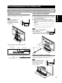
Preventing Equipment from Falling Over ........... 21
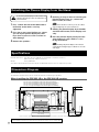
Detaching the Plasma Display from the Stand .... 22
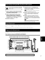
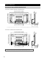
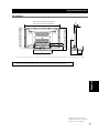
Specifications ........................................................ 22
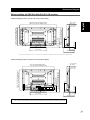
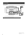
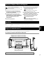
Dimensions Diagram ............................................ 22
Installation
¶ Consult your dealer if you encounter any difficulties
with this installation.
¶ Pioneer is not liable for any damage resulting from
improper installation, improper use, modification, or
natural disasters.
Cautions
This product is a table top stand exclusively designed for
plasma displays (PDP-505XDE / PDP-505HDE / PDP-
505HDG / PDP-435XDE / PDP-435HDE / PDP-435FDE /
PDP-435HDG / PDP-504HD / PDP-5040HD / PDP-504HDE /
PDP-504HDG / PDP-504HDC / PDP-5045HD / PDP-434HD /
PDP-4340HD /PDP-434HDE / PDP-434HDG / PDP-434HDC /
PDP-4345HD) from Pioneer. Use with other model is
capable of resulting in instability causing possible injury. For
further information, please contact the store where you
purchased your display.
Do not install or modify the product other than specified.
Do not use this stand for a plasma display other than those
designated and do not modify it or use it for other pur-
poses.
Improper installation is extremely dangerous because it
may result in it falling over or other accident.
Installation Location
• Select a location that is strong enough to support the
weight of the stand and the displays.
• Make sure to place it in a level and stable location.
• Do not install it outdoors, at a hot spring, or near a beach.
• Do not install the stand where it may be subjected to
vibration or shock.
Assembling and Installation
• Assemble the stand in accordance with the assembly
instructions and securely attach all screws at the
designated locations.
There have been cases where unforeseen accidents
such as the equipment breaking or falling over
occurred after the installation of the display because
the stand was not installed as instructed.
• The display must always be installed by two or more
people to assure it is installed safely.
• Before installation, turn off the power for the display
and peripheral devices then remove the power cord
plug from the power outlet.
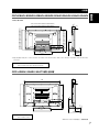
This product rotates 10° to the left and right and inclines 2°
forward and backward.
Do not place objects within the range of rotation of this
product and the plasma display. Install this product so that
during routine use or when it is rotated, it does not protrude
from the rack or other location it has been installed. Failure
to do so could cause unforeseen accidents such as the
equipment breaking or falling over (see page 19).
Prevent accidents caused by the product falling over by
taking reliable measures to prevent it from falling over (see
Page 21).
CAUTION
This symbol refers to a hazard or unsafe practice which
can result in personal injury or property damage.

15
En
English
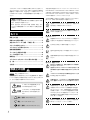
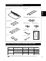
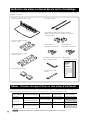
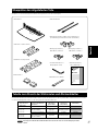
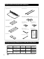
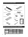
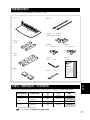
Table top stand x 1
Support columns S x 2
[short columns]
Support columns L x 2
[long columns]
Spacers x 2
Cable binders x 2
Installation screws 1 (M8 x 16 mm: silver) x 4
[used to anchor the support columns and the table top stand]
Installation screws 2
(M8 x 30 mm: black) x 2
Installation screws 3
(M8 x 40 mm: black) x 2
Hexagonal wrench x 1
(Diagonal size: 6 mm)
Operating instructions
(this document) x 1
C wrench x 1 (10 mm)
Spacers
Not used
Recommended
Recommended
Recommended
Cannot be used
Can be used* Cannot be used
PDP-S21-LR
Can be used* Cannot be used
PDP-S22-LR
PDP-S25-LR
PDP-S26-LR
Used Used
Cannot be usedCan be used*
Combined speaker
numbers
–
Speaker installation location
Both sides of the plasma display
(or not used)
Both sides of the plasma display
(or not used)
Bottom of the plasma display
Support columns S
(short columns)
Support columns L
(long columns)
*: Can be used when the screen is located in a high position.
Note
The PDP-S25-LR and the PDP-S26-LR speakers cannot be installed at the bottom of the plasma display.
Checking the Enclosed Parts
Check to make sure that you have all the enclosed parts before assembly and installation.
Support Columns/Spacers Used/Not Used Table
The parts of this stand that are used vary depending on the speakers that you have purchased and on their installation
location on the plasma display. Please select the parts you use according to the following table.
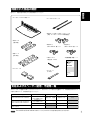
Operating instructions
Mode d’emploi
Bedienungsanleitung
Istruzioni per l’uso
Gebruiksaanwijzing
Manual de instrucciones
Table top stand
Support de couverture de table
Tischständer
Supporto di tavolo
Tafelbladstaander
Soporte de mesa
PDK-TS05

16
En
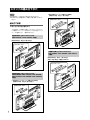
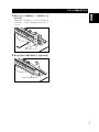
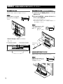
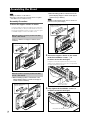
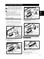
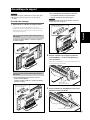
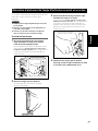
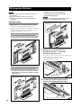
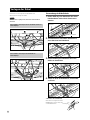
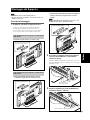
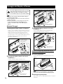
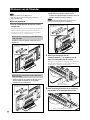
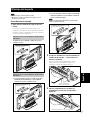
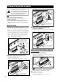
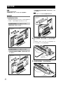
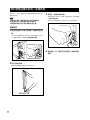
Assembling the Stand
2 Secure the support column to the stand
with the Installation screws 1 (4
locations on the left and right).
Using the enclosed hexagonal wrench, first loosely
attach the top attachment screw, then loosely attach
the bottom attachment screw.
Installation screws 1
(M8 x 16 mm: silver)
Fully tighten the attachment screws.
3 Fully tighten the Installation screws (4
locations on the left and right).
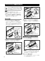
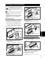
When installing speakers at the bottom of the
plasma display [Support column used: support
column L (long columns)]
Note
The PDP-S25-LR and PDP-S26-LR cannot be installed at
the bottom of the plasma display.
Support column used:
support column L
When the speakers you have purchased are PDP-
S21-LR or PDP-S22-LR.
When installing speakers on both sides of the
plasma display [Support column used: support
column S (short columns)]
Support column used:
support column S
Support column used:
support column S
Note
Always assemble it on a flat table etc.
Insert the screws in the holes vertically and do not tighten
them with more force than necessary.
Assembly Procedure
1 Select the support columns to attach.
Select the support columns according to the settings of
the speakers that you have purchased with reference to
the following stipulation (Only one type of the two types
of available support columns should be used).
When the speakers you have purchased are PDP-
S25-LR or PDP-S26-LR.
[Support column used: support column S (short
columns)]

17
En
English
Installation screws 2
(M8 x 30 mm: black)
Spacer
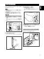
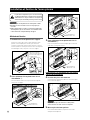
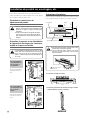
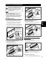
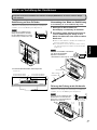
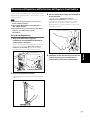
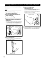
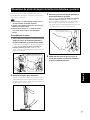
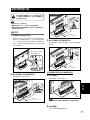
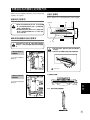
Attaching the Plasma Display
The weight of a 50 inch plasma display is about 40 kg
(88 lbs), that of a 43 inch model is about 30 kg (66 lbs),
they have no depth, and are unstable. Therefore, at
least two people must assemble and install them.
Note
Be sure to install it on a flat stable location.
Insert the screws in the holes vertically and do not tighten
them with more force than necessary.
Make sure that you install the support columns reliably
according to the settings of the type of speakers you have
purchased with reference to the procedure in Assembling
the Stand.
Attachment Method
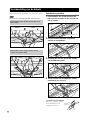
1 Attaching the plasma display to the stand.
Fit the stand’s support columns to the bottom of the
plasma display as indicated by the arrows, then slowly
insert them vertically. Be extremely careful not to insert the
support columns of the stand into any part of the plasma
display other than the stand insertion slots. Note that doing
so might damage the plasma display panel or its ports or
result in the warping of the stand.
Line up the column
supports with the bottom
of the plasma display as
indicated in the accompa-
nying diagram.
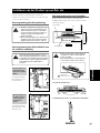
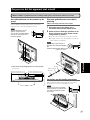
2 Securing the plasma display with
Installation screws 2.
Secure them using the enclosed hexagonal wrench.
Illustration: when using support columns S
Installation screws 2
(M8 x 30 mm: black)
Illustration: when using support columns L
3 Securing the plasma display with
Installation screws 3.
Attach the plasma display at the points indicated by the
arrows using the enclosed hexagonal wrench.
Installation screws 3
(M8 x 40 mm: black)
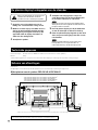
5 Attaching the speakers.
Refer to the operating instructions for the speaker for
the installation method.
Only when attaching speakers at the bottom
of the plasma display
4 Inserting the spacers.
Insert the spacers in the holes on the rotating platform
of the stand.
Caution
Note
Please do not use the spacer if the speakers are to be
attached to both sides of the plasma display.

18
En
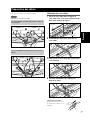
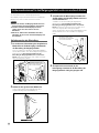
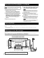
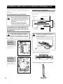
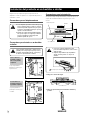
On this stand, you can adjust the angle of inclination of the
plasma display within a range of 2° forward or backward
according to your preference.
Note
Be sure to adjust the angle only after you have
attached the plasma display.
Be sure to install it on a flat table or other flat
surface.
Be sure to hold the top of the plasma display
with your hand while adjusting the angle.
Adjustment Procedure
1 Loosen the forward/backward inclination
anchor bolts using the enclosed C wrench.
While being sure to hold the top of the plasma display
with your hand, loosen the forward/backward
inclination anchor bolts on the left and right sides by
rotating them upwards using the enclosed C wrench.
2 Set the angle you prefer.
Set the angle you prefer by slowly moving the plasma
display.
3 Tighten the forward/backward inclination
anchor bolts.
Firmly tighten the forward/backward inclination
anchor bolts on the left and right sides by rotating
them downward using the enclosed C wrench.
Be sure to hold the top of the plasma display with your
hand until you have fully tightened the bolts.
4 Check once more to make sure that the
forward/backward inclination anchor bolts
are fully tightened.
2˚
2˚
Forward/Backward Angle of Inclination Adjustment Mechanism
Forward/backward
inclination anchor bolt
Loosening
Forward/backward
inclination anchor bolt
Tightening

19
En
English
10˚
10˚
2˚
2˚
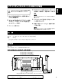
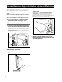
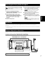
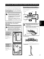
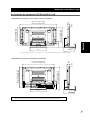
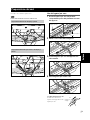
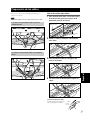
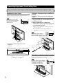
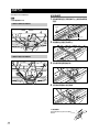
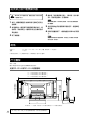
Installing the Product on a Rack etc.
Be sure to observe the following precautions when moving
or installing this product with a plasma display into a rack or
other enclosure.
Precautions when moving
When moving the product more than a few
meters, first remove the speaker, then remove
the plasma display from the stand and move the
speaker, plasma display, and stand separately.
When detaching the plasma display from the
stand, be sure to follow the procedure described
in “Detaching the Plasma Display from the
Stand” on page 22.
Precautions when installing in a rack
or other enclosure
When installing in a rack or other enclosure, hold the
plasma display by the handles located on the rear
and bottom of the plasma display. If you hold the
speakers, they may be damaged or twisted.
When installing
speakers on both
sides of the plasma
display
Hold the plasma display
by its handles and from
the bottom.
When installing
speakers at the
bottom of the
plasma display
Hold the plasma display
by its handles and from
the sides.
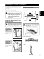
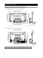
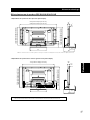
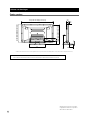
Installation precautions
Make sure that you always secure a space at least as large
as that shown in the following diagram in front of and
behind the table top stand.
If the stand protrudes from the rack, it could cause
unforeseen accidents such as the equipment break-
ing or falling over.
When rotating, take care not to allow the display
to bump into walls or surrounding objects.
Min. 10 mm
(13/32 inch)
Plasma display
Rack
Table top stand
Min. 30 mm
(1-3/16 inch)
Back
Depth of the rack
420 mm (16-9/16 inch)
or more recommended
Front
Range of angle rotation
Forward/backward angle of inclination adjustment
range
Caution
Caution
Caution
Protrusion is dangerous.

20
En
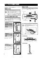
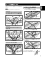
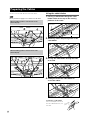
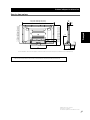
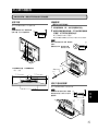
Preparing the Cables
Use the enclosed cable binders to bind the cables.
Note
Be very careful not to apply force to the bases of the cables.
When installing speakers on both sides of the
plasma display
When installing speakers at the bottom of the
plasma display
Using the cable binders
1 Passing a cable binder though the cable
binder holder on the top of the rotating
platform of the stand.
Cable binder
Cable binder holder
2 Gathering cables and placing them on the
cable binder.
3 Passing the cable binder through the hole
on its end.
4 Pulling the end of the cable binder to
secure the cables.
Removing a cable binder
If the secured part is removed
from the cable binder hole, it is
unlocked.
Hole
Secured
part
La page est en cours de chargement...
La page est en cours de chargement...
La page est en cours de chargement...
La page est en cours de chargement...
La page est en cours de chargement...
La page est en cours de chargement...
La page est en cours de chargement...
La page est en cours de chargement...
La page est en cours de chargement...
La page est en cours de chargement...
La page est en cours de chargement...
La page est en cours de chargement...
La page est en cours de chargement...
La page est en cours de chargement...
La page est en cours de chargement...
La page est en cours de chargement...
La page est en cours de chargement...
La page est en cours de chargement...
La page est en cours de chargement...
La page est en cours de chargement...
La page est en cours de chargement...
La page est en cours de chargement...
La page est en cours de chargement...
La page est en cours de chargement...
La page est en cours de chargement...
La page est en cours de chargement...
La page est en cours de chargement...
La page est en cours de chargement...
La page est en cours de chargement...
La page est en cours de chargement...
La page est en cours de chargement...
La page est en cours de chargement...
La page est en cours de chargement...
La page est en cours de chargement...
La page est en cours de chargement...
La page est en cours de chargement...
La page est en cours de chargement...
La page est en cours de chargement...
La page est en cours de chargement...
La page est en cours de chargement...
La page est en cours de chargement...
La page est en cours de chargement...
La page est en cours de chargement...
La page est en cours de chargement...
La page est en cours de chargement...
La page est en cours de chargement...
La page est en cours de chargement...
La page est en cours de chargement...
La page est en cours de chargement...
La page est en cours de chargement...
La page est en cours de chargement...
La page est en cours de chargement...
La page est en cours de chargement...
La page est en cours de chargement...
La page est en cours de chargement...
La page est en cours de chargement...
La page est en cours de chargement...
La page est en cours de chargement...
La page est en cours de chargement...
La page est en cours de chargement...
La page est en cours de chargement...
La page est en cours de chargement...
La page est en cours de chargement...
La page est en cours de chargement...
La page est en cours de chargement...
La page est en cours de chargement...
La page est en cours de chargement...
La page est en cours de chargement...
La page est en cours de chargement...
La page est en cours de chargement...
La page est en cours de chargement...
-
 1
1
-
 2
2
-
 3
3
-
 4
4
-
 5
5
-
 6
6
-
 7
7
-
 8
8
-
 9
9
-
 10
10
-
 11
11
-
 12
12
-
 13
13
-
 14
14
-
 15
15
-
 16
16
-
 17
17
-
 18
18
-
 19
19
-
 20
20
-
 21
21
-
 22
22
-
 23
23
-
 24
24
-
 25
25
-
 26
26
-
 27
27
-
 28
28
-
 29
29
-
 30
30
-
 31
31
-
 32
32
-
 33
33
-
 34
34
-
 35
35
-
 36
36
-
 37
37
-
 38
38
-
 39
39
-
 40
40
-
 41
41
-
 42
42
-
 43
43
-
 44
44
-
 45
45
-
 46
46
-
 47
47
-
 48
48
-
 49
49
-
 50
50
-
 51
51
-
 52
52
-
 53
53
-
 54
54
-
 55
55
-
 56
56
-
 57
57
-
 58
58
-
 59
59
-
 60
60
-
 61
61
-
 62
62
-
 63
63
-
 64
64
-
 65
65
-
 66
66
-
 67
67
-
 68
68
-
 69
69
-
 70
70
-
 71
71
-
 72
72
-
 73
73
-
 74
74
-
 75
75
-
 76
76
-
 77
77
-
 78
78
-
 79
79
-
 80
80
-
 81
81
-
 82
82
-
 83
83
-
 84
84
-
 85
85
-
 86
86
-
 87
87
-
 88
88
-
 89
89
-
 90
90
-
 91
91


Pioneer PDK-TS05 Le manuel du propriétaire
- Taper
- Le manuel du propriétaire
dans d''autres langues
- italiano: Pioneer PDK-TS05 Manuale del proprietario
- English: Pioneer PDK-TS05 Owner's manual
- español: Pioneer PDK-TS05 El manual del propietario
- Deutsch: Pioneer PDK-TS05 Bedienungsanleitung
- Nederlands: Pioneer PDK-TS05 de handleiding
- 日本語: Pioneer PDK-TS05 取扱説明書
Documents connexes
-
Pioneer PDK-TS36B Le manuel du propriétaire
-
-
-
Pioneer PDK-TS25(B) Le manuel du propriétaire
-
-
-
-
-
-