Powerfist 9113465 Le manuel du propriétaire
- Taper
- Le manuel du propriétaire

V1.0 9113465
Please read and understand all instructions before use. Retain this manual for
future reference.

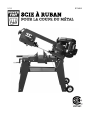
9113465 4 x 6 in. Metal Cutting Band Saw V1.0
2 For technical questions call 1-800-665-8685
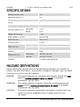
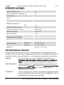
SPECIFICATIONS
Voltage Rating (V AC) 120
Amperage Rating (A) 6.5
Horse Power (HP) 1
Phase 1
Frequency Rating (Hz) 60
Cutting Capacity (in.) Rectangle 4 x 6
Round 4-1/2
Speed Rating (RPM) 1,750
Blade Speed(s) (ft/min) 80/120/200
Blade Size (in.) 64-1/2 x 1/2
Cutting Angle (°) 0 to 45
Table Size (in.) On the body 12 x 7-1/2 in
On the bracket 9-7/16 x 9-7/16
Material Steel
Dimensions (in.) Horizontal 38-5/8 x 18 x 38
Vertical 42-1/4 x 22 x 56
Includes 3, 4 and 6 mm wrenches
HAZARD DEFINITIONS
Please familiarize yourself with the hazard notices found in this manual. A
notice is an alert that there is a possibility of property damage, injury or death
if certain instructions are not followed.
DANGER! This notice indicates an immediate and specific hazard that will
result in severe personal injury or death if the proper
precautions are not taken.
WARNING! This notice indicates a specific hazard or unsafe practice that
could result in severe personal injury or death if the proper
precautions are not taken.
CAUTION! This notice indicates a potentially hazardous situation that may
result in minor or moderate injury if proper practices are
not taken.

V1.0 4 x 6 in. Metal Cutting Band Saw 9113465
Visit www.princessauto.com for more information 3
NOTICE! This notice indicates that a specific hazard or unsafe practice will
result in equipment or property damage, but not personal injury.
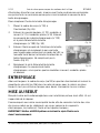
INTRODUCTION
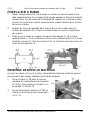
Accurately cuts workpieces up to a 4 x 6 in. cross-section. The Band Saw has a
three-speed motor to cut everything from brass and aluminum to rugged alloy
and tool steels. The saw has a two-position rocker switch with a safety lock.
The mitre plate on the horizontal cutting bed has a range of 0° to 45°. The Band
Saw includes the Saw Blade and mobile stand.
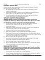
WORK AREA
1. Operate in a safe work environment. Keep your work area clean, well-lit
and free of distractions.
2. Keep anyone not wearing the appropriate safety equipment away from the
work area.
3. Store unused tools properly in a safe and dry location to prevent rust or
damage. Lock tools away and keep out of the reach of children.
4. Do not install or use in the presence of flammable gases, dust or liquids.
PERSONAL SAFETY
WARNING! Wear personal protective equipment approved by the Canadian
Standards Association (CSA) or American National Standards Institute (ANSI).
PERSONAL PROTECTIVE EQUIPMENT
1. Always wear impact safety goggles that provide front and side protection
for the eyes. Eye protection equipment should comply with CSA Z94.3-07
or ANSI Z87.1 standards based on the type of work performed.
2. Wear the appropriate type of full-face shield in addition to safety googles,
as the work can create chips, abrasive or particulate matter.
3. Wear gloves that provide protection based on the work materials or to
reduce the effects of tool vibration.
a. Do not wear gloves when operating a tool that can snag the material
and pull the hand into the tool.
4. Wear protective clothing designed for the work environment and tool.
5. Non-skid footwear is recommended to maintain footing and balance in the
work environment.
6. Wear steel toe footwear or steel toe caps to prevent a foot injury from
falling objects.
7. Wear the appropriate rated dust mask or respirator.

9113465 4 x 6 in. Metal Cutting Band Saw V1.0
4 For technical questions call 1-800-665-8685
PERSONAL PRECAUTIONS
Control the tool, personal movement and the work environment to avoid
personal injury or damage to tool.
1. Do not operate any tool when tired or under the influence of drugs,
alcohol or medications.
2. Avoid wearing clothes or jewelry that can become entangled with the
moving parts of a tool. Keep long hair covered or bound.
3. Do not overreach when operating a tool. Proper footing and balance
enables better control in unexpected situations.
SPECIFIC SAFETY PRECAUTIONS
WARNING! DO NOT let comfort or familiarity with product (gained from
repeated use) replace strict adherence to the tool safety rules. If you use this
tool unsafely or incorrectly, you can suffer serious personal injury.
1. Use the correct tool for the job. This tool was designed for a specific
function. Do not modify or alter this tool or use it for an
unintended purpose.
2. Make sure the tool is located on a flat, level, sturdy surface capable of
supporting the weight of the tool and workpiece.
3. Always use the vise to clamp the material in place.
4. Make sure the blade is sharp, undamaged and properly aligned.
5. Make sure to firmly press the workpiece against the Table and/or secure
the vise. Never cut freehand as the material may twist out of your hand or
your hand may be drawn into the saw blade.
6. Never cut more than one workpiece at a time.
7. Never turn the Band Saw ON before clearing everything off the table,
except the workpiece and related support devices.
8. Read and understand all warning labels on the tool.
9. Never stand on the tool. Serious injury could occur if the tool tips over or
if the cutting blade is unintentionally contacted.
BAND SAW PRECAUTIONS
DANGER! When the tool is in operation, keep hands away from the saw blade
and the area it is being applied to. Failure to follow this warning will result in
amputation, serious personal injury or death.
1. Always make sure the band saw is clean before use.
2. Always be sure all components are mounted properly and securely before
using tool. Tighten all clamps before turning power on.

V1.0 4 x 6 in. Metal Cutting Band Saw 9113465
Visit www.princessauto.com for more information 5
3. Maintain proper adjustment of blade tension, blade guides, and blade guide
bearings. Lower the body frame, spin the blade and check for clearance. If the
blade hits anything, adjust the blade (see Adjustments under Operations).
4. Always handle the band saw blade with care when mounting or removing
it. Wear heavy-duty work gloves to protect your hands.
5. Always wait until the motor has reached full speed before starting a cut.
6. Always be aware of the position of your hands relative to the blade. Avoid
awkward hand positions where a sudden slip could cause a hand to move
into the blade.
7. Adjust upper guide to just clear workpiece
8. Never reach behind or beneath the blade.
9. Never leave the tool unattended when it is plugged into an electrical
outlet. Turn off the tool and unplug it from its electrical outlet
before leaving.
10. Turn off the tool and allow the blade to stop on its own. Do not press
against the Saw Blade to stop it.
11. Do not lean on the Band Saw when the tool is in its upright position.
12. When moving the Band Saw, always have the body frame (#93) lowered to its
horizontal position and the Locking Pin (#126) inserted in the Pivot (#47).
POWER TOOL PRECAUTIONS
1. Do not use a power tool with a broken or inoperative
trigger/power switch.
2. Do not allow the tool to run without load for an extended period of time,
as this will shorten its life.
3. Do not cover the air vents. Proper cooling of the motor is necessary to
ensure normal life of the tool.
4. Avoid unintentional starting. Ensure the switch is off when connecting to
the power source.
5. After making adjustments, make sure that any adjustment devices are
securely tightened.
6. Remove adjusting keys and wrenches before turning the tool on. A wrench
or a key that is left attached to a rotating part of the tool increases the
risk of personal injury.
7. Never force the tool. Excessive pressure could break the tool, resulting in
damage to your workpiece or serious personal injury. If your tool runs

9113465 4 x 6 in. Metal Cutting Band Saw V1.0
6 For technical questions call 1-800-665-8685
smoothly under no load, but does not run smoothly under load, then
excessive pressure is being used.
8. Do not touch an operating motor. Motors can operate at high temperatures
and can cause a burn injury.
9. Only use accessories that are specifically designed for use with the tool.
Ensure the accessory is tightly installed.
10. Only use an accessory that exceeds the No Load Speed rating
(see Specifications).
CUTTING TOOL PRECAUTIONS
WARNING! Some surfaces contain materials which can be toxic. When working
on materials that may contain lead, asbestos, copper chromium arsenate or
other toxic materials, extra care should be taken to avoid inhalation and
minimize skin contact.
The term cutting accessory is used to represent a cutting blade, cutting wheel
or a cutting bit.
1. Never force the tool’s cutting accessory to cut. Forcing the tool will slow
down the speed of the cutting accessory, causing it to bind or kickback.
Apply gentle pressure and allow the cutting accessory to do the cutting.
2. Never use a dull or damaged cutting accessory.
a. A dull or improperly set cutting accessories produce a narrow kerf that
can cause excessive friction on the cutting accessory, resulting in
binding or a kickback. Keep the cutting accessory’s edge sharp
and clean.
b. A dull cutting accessory requires more force to use the tool, possibly
causing the accessory to break. This may cause an injury.
3. Only use a cutting accessory of the recommended size (see Specifications).
4. Use the correct mounting hardware. The mounting hardware is designed
to hold the cutting accessory on the tool to allow optimum performance
and safety of operation. Mismatched mounting hardware may result in a
tool malfunction and cause an injury.
5. Do not touch the cutting accessory or the workpiece surface cut with this
tool. They may be hot and could inflict a burn injury.

V1.0 4 x 6 in. Metal Cutting Band Saw 9113465
Visit www.princessauto.com for more information 7
KICKBACK PRECAUTIONS
Kickback is a sudden reaction to a pinched or snagged cutting accessory
caught on the material. The material can be ejected and inflict a serious injury
on the user or a bystander. Kickback can also damage the tool or workpiece.
Kickback can be avoided by taking proper precautions:
1. Maintain a firm grip on the material and position your body and arms to
allow you to resist a kickback. Kickback can propel the material in the
direction of the cutting accessory’s rotation.
a. Use a clamp to hold the material if the tool includes a clamping system.
2. Use special care when working on corners, sharp edges or flexible
material. These workpieces have a tendency to snag the cutting accessory.
3. Only use cutting accessories designed for the tool.
POWER CORD
1. Insert the power cord plug directly to the power supply whenever
possible. Use extension cords or surge protectors only when the tool's
power cord cannot reach a power supply from the work area.
a. Use in conjunction with a Ground Fault Circuit Interrupter (GFCI). If
operating a power tool in a damp location is unavoidable, the use of a
GFCI reduces the risk of electric shock. It is recommended that the
GFCI should have a rated residual current of 30 mA or less.
2. Do not operate this tool if the power cord is frayed or damaged as an electric
shock or surge may occur, resulting in personal injury or property damage.
a. Inspect the tool's power cord for cracks, fraying or other faults in the
insulation or plug before each use.
b. Discontinue use if a power cord feels more than comfortably warm
while operating the tool.
c. Have the power cord replaced by a qualified service technician.
3. Keep all connections dry and off the ground to reduce the risk of electric
shock. Do not touch plug with wet hands.
4. Prevent damage to the power cord by observing the following:
a. Do not pull on the cord to disconnect the plug from an outlet.
b. Keep cord away from heat, oil, sharp edges or moving parts.
5. Do not allow people, mobile equipment or vehicles to pass over
unprotected power cords.
a. Position power cords away from traffic areas.

9113465 4 x 6 in. Metal Cutting Band Saw V1.0
8 For technical questions call 1-800-665-8685
b. Place cords in reinforced conduits.
c. Place planks on either side of the power cord to create a protective trench.
6. Do not wrap cord around the tool as sharp edges may cut insulation or
cause cracks if wound too tight. Gently coil cord and either hang on a
hook or fasten with a device to keep cord together during storage.
ELECTRICAL SAFETY
WARNING! Do not touch or handle a live tool with any part of your body that is
wet or damp. Wet skin reduces resistance to electrical current, increasing the
danger of a serious or fatal shock.
WARNING! To reduce risk of electric shock, be certain that the plug is connected
to a properly grounded receptacle.
1. Disconnect tool from power source before cleaning, servicing, changing
parts/accessories or when not in use.
2. Protect yourself against electric shocks when working on electrical
equipment. Avoid body contact with grounded surfaces. There is an
increased chance of electrical shock if your body is grounded.
3. Do not expose the tool to rain or wet conditions. Water entering a power
tool will increase the risk of electric shock.
4. Do not disconnect the power cord in place of using the ON/OFF switch on
the tool. This will prevent an accidental startup when the power cord is
plugged into the power supply.
a. In the event of a power failure, turn off the machine as soon as the
power is interrupted. The possibility of accidental injury could occur
if the power returns and the unit is not switched off.
5. Do not alter any parts of the tool or accessories. All parts and accessories are
designed with built-in safety features that may be compromised if altered.
6. Make certain the power source conforms to requirements of your
equipment (see Specifications).
7. When wiring an electrically driven device, follow all electrical and safety
codes, as well as the most recent Canadian Electrical Code (CE) and
Canadian Centre for Occupational Health and Safety (CCOHS).
8. Grounded tools must be plugged into an outlet that is properly installed and
grounded in accordance with all codes and ordinances. Check with a qualified
electrician if you are in doubt as to whether the outlet is properly grounded. If

V1.0 4 x 6 in. Metal Cutting Band Saw 9113465
Visit www.princessauto.com for more information 9
the tool should electronically malfunction or break down, grounding provides
a low resistance path to carry electricity away from the user.
a. Never remove the grounding prong or modify the plug in any way, as
this will render the tool unsafe.
b. Do not use any adapter plugs.
9. This device is only for use on 120 V (single phase) and is equipped with a
3-prong grounded power supply cord and plug.
10. DO NOT use this device with a 2-prong wall receptacle.
a. Choose an available 3-prong power outlet.
b. Replace 2 prong outlet with a grounded 3-prong receptacle, installed
in accordance with the CE Code and local codes and ordinances.
WARNING! All wiring should be performed by a qualified electrician.
ELECTROMAGNETIC FIELDS
WARNING! Shut off the electrical tool or device and move away if you feel faint,
dizzy, nausea or shocks. Seek medical attention.
Electromagnetic Fields (EMF) can interfere with electronic devices such as
pacemakers. Anyone with a pacemaker should consult with their doctor before
working with or near a tool that generates an EMF. The following steps can
minimize the effects of electromagnetic fields.
1. Keep the power source and any power cables as far away from the user as
practical. A minimum of 24 in. is recommended.
2. Avoid long and regular bursts of energy while operating the tool. Use the
tool for short or intermittent periods of time. This will prevent a
pacemaker from interpreting the signal as a rapid heartbeat.
3. Alert other people in the work area, so they can take precautions or can
watch out for those with a pacemaker.
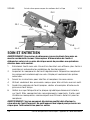
MOTOR PRECAUTION
NOTICE! To avoid motor damage, this motor should be blown out with dry,
compressed air or vacuumed frequently to keep particulates and dust from
interfering with normal motor ventilation.
1. If the motor does not start, turn the tool off and unplug it. Check the saw
blade to make sure it turns freely. If the blade is free, try to start the
motor again.

9113465 4 x 6 in. Metal Cutting Band Saw V1.0
10 For technical questions call 1-800-665-8685
2. If the motor still does not start, check the motor’s carbon brushes. Replace
with new carbon brushes if they are worn down.
3. Connect this tool with a fuse or circuit breaker. Using the wrong size fuse can
damage the motor. Fuses may ‘blow’ or circuit breakers may trip frequently if:
a. Motor is overloaded. Overloading can occur if you feed the material
to the saw too rapidly or start/stop too many times in a short period.
b. Voltage not more than 10% above or below the nameplate voltage can
handle normal loads. For heavy loads, the voltage may drop too low
for the motor to operate. This can be caused by a small gauge wire in
the supply circuit or an overly long supply circuit wire. Always check
the connections, the load and the supply circuit whenever motor
does not work well.
VIBRATION PRECAUTIONS
1. This tool vibrates during use. Repeated or long-term exposure to vibration
may cause temporary or permanent physical injury. Take frequent breaks
when using the tool.
2. If you feel any medical symptoms related to vibrations (such as tingling,
numbness, and white or blue fingers), seek medical attention as soon
as possible.
3. Wear suitable gloves to reduce the effects of vibration.
4. DO NOT use this tool before consulting a physician if one of the
following applies:
a. Pregnant
b. Impaired blood circulation to the hands
c. Past hand injuries
d. Nervous system disorders
e. Diabetes
f. Raynaud's Disease
UNPACKING
WARNING! Do not operate the tool if any part is missing. Replace the missing
part before operating. Failure to do so could result in a malfunction and
personal injury.
Remove the parts and accessories from the packaging and inspect for damage.
Make sure that all items in the parts list are included.

V1.0 4 x 6 in. Metal Cutting Band Saw 9113465
Visit www.princessauto.com for more information 11
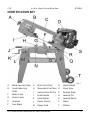
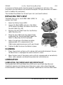
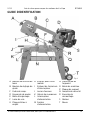
IDENTIFICATION KEY
A Blade Tension Knob
B Guide Adjusting
Knob
C Body Frame
D Pulley Cover
E Gearbox
F Saw Blade
G Mitre Vise Plate
H Moveable Vise Place
I Switch Push-Off Tip
J Feed Handle
K Hand Wheel
L Power Switch
M Power Cord
N Machine Bed
O Stock Stop
P Support Plate
Q Locking Pin
R Locking Notch
S Motor
T Wheels
Fig.
1

9113465 4 x 6 in. Metal Cutting Band Saw V1.0
12 For technical questions call 1-800-665-8685
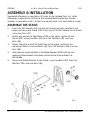
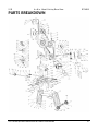
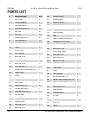
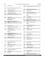
ASSEMBLY & INSTALLATION
Numbered references in parenthesis (#1) refer to the included Parts List. Letter
references in parenthesis (A) refer to the included Identification Key. Dashed
numbers in parenthesis (Fig. 1-1) refer to a specific point in an illustration or image.
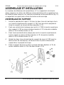
ASSEMBLE THE STAND
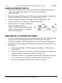
1. Insert the Pull Handle (#12) into the two mounting holes located in the
upper section of one Stand (#10). Then secure the Pull Handle to the Stand,
using two Pins (#11).
2. Attach one end of the Tool Plate (#128) to the upper section of one
Stand (#10), using two Bolts (#9), four Flat Washers (#8), and two
Nuts (#6).
3. Attach the other end of the Tool Plate to the upper section of the
remaining Stand, using two Bolts (#9), four Flat Washers (#8), and two
Nuts (#6).
4. Align the two mounting holes in the Wheel Bracket (#130) with the two
mounting holes located in the lower section of the Stand without the
Pull Handle.
5. Secure the Wheel Bracket to the Stand, using two Bolts (#9), four Flat
Washers (#8), and two Nuts (#6).
Fig. 2

V1.0 4 x 6 in. Metal Cutting Band Saw 9113465
Visit www.princessauto.com for more information 13
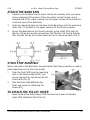
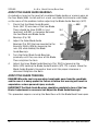
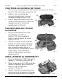
ATTACH THE BAND SAW
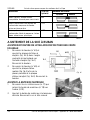
1. Carefully set the Band Saw on top of the Stand assembly with assistance
and an adequate lifting device. Place the motor end of the Saw at the
wheeled end of the stand, making sure the upper section of the Stand fits
inside the base of the Band Saw.
2. Align the mounting holes on the base of the Band Saw with the mounting
holes (Fig. 3-1) located on the upper sections of the Stand assembly.
3. Secure the Band Saw to the Stand assembly, using a Bolt (#13) and Flat
Washer (#3) on the outside and another Flat Washer (#3), Spring Washer
(#4), and Nut (#5) on the inside of each of the six mounting holes (Fig. 4).
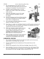
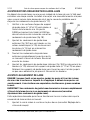
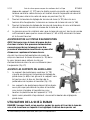
STOCK STOP ASSEMBLY
When mounted to the Band Saw, the adjustable Stock Stop assembly is used to
make repetitive cuts of the same length.
1. Slide the Shaft (#19) into the mounting
hole in the Machine Bed (#122), and
secure the Shaft by tightening the Set
Screw (#49 [Fig. 5]).
2. Slide the Stock Stop (#18) onto the
Shaft, and secure by tightening the
Screw (#17).
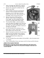
TO ATTACH THE PULLEY COVER
1. Open the lid of the Pulley Cover (#101) and position it over the Spindle
Shaft (#97) and Motor Shaft (Fig. 6-1).
Fig. 3
Fig. 4
Fig. 5

9113465 4 x 6 in. Metal Cutting Band Saw V1.0
14 For technical questions call 1-800-665-8685
2. Align the mounting hole in the Pulley
Cover with the mounting hole in the
Body Frame (#93).
3. Secure the Pulley Cover to the Band Saw,
using one Screw (#89), Spring
Washer (#7) and Flat Washer (#8).
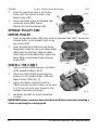
SPINDLE PULLEY AND
MOTOR PULLEY
1. Slide the Spindle Pulley (#99) fully onto the Spindle Shaft (#97). Secure the
Spindle Pulley to the Spindle Shaft using
one Screw (#52).
2. Insert the Shaft Key (#51) in the slot on the
Motor Shaft. Align the slot in the Motor Pulley
(#105) with the Shaft Key. Slide the Motor
Pulley fully onto the Motor Shaft. Secure the
Motor Pulley to the Motor Shaft using one
Screw (#52).
INSTALL THE V-BELT
1. Loosen the Bolt (#108) and press the Motor
(#115) toward the Body (Fig. 8).
2. Place the V-Belt (#100) around the top
grooves in the Spindle Pulley (#99) and
Motor Pulley (#105 [Fig. 7]).
3. Adjust the Motor’s position until the
V-Belt’s tension will only allow you to push
it in 1/2 an inch with your thumb at the
midpoint between the pulleys.
4. Retighten the Bolt to secure the Motor
in place.
IMPORTANT! Always securely close the Lid on the Pulley Cover after installing a
V-Belt or adjusting the cutting speed.
Fig. 7
Fig. 8
Fig. 6
6-1

V1.0 4 x 6 in. Metal Cutting Band Saw 9113465
Visit www.princessauto.com for more information 15
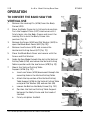
OPERATION
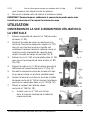
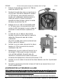
TO CONVERT THE BAND SAW FOR
VERTICAL USE
1. Remove the Locking Pin (#126) from the Body
Frame (#93).
2. Raise the Body Frame to its full vertical position.
Turn the Support Plate (#127) clockwise until it
firmly locks into the Body Frame and insert the
Locking Pin to lock the Body Frame into
position (Fig. 9).
3. Remove the Screw (#142) and Flat Washer (#141) to
open the Blade Back Cover (#82 [Fig. 10])
4. Remove two Screws (#78) and remove the
Horizontal Cutting Guard (#71 [Fig. 11]).
5. Close the Blade Back Cover and secure with the
Screw and Flat Washer.
6. Guide the Saw Blade through the slot in the Vertical
Cutting Table (#134), and secure the Vertical Cutting
Table in position with the two Screws (#78 [Fig. 12]).
7. Mount the Vertical Cutting Table
Support (#136 [Fig. 13]).
a. Insert one Screw (#135) downward through the
mounting hole in the Vertical Cutting Table.
b. Attach the top section of the Vertical Cutting
Table Support (#136) to the Vertical Cutting Table
using one Flat Washer (#8) and one Nut (#6).
c. Loosen the Bolt on the Body Frame (Fig. 13-1).
d. Position the Vertical Cutting Table Support
between the Body Frame and the head of
the Bolt.
e. Firmly retighten the Bolt.
Fig. 9
Fig. 10
Fig. 11
Fig. 12
13-1
Fig. 13

9113465 4 x 6 in. Metal Cutting Band Saw V1.0
16 For technical questions call 1-800-665-8685
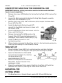
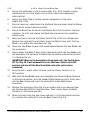
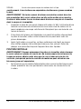
CONVERT THE BAND SAW FOR HORIZONTAL USE
IMPORTANT! Notching, slitting and contour work is best done with the Band
Saw in its vertical position.
1. Remove the screws (#78) holding the Vertical Cutting Table (#134) in place (Fig.
11 and 12).
2. Loosen the Bolt and guide the Vertical Cutting Table Support assembly
away from the Saw Blade (Fig. 13).
3. Remove the Screw (#113) and Flat Washer (#114) to open the Blade Back
Cover (#115 [Fig. 10]).
4. Guide the Horizontal Cutting Guard (#71)
around the Saw Blade and secure in place with
the Screws (#78).
5. Close the Blade Back Cover and secure with the
Screw and Flat Washer.
6. Remove the Locking Pin (#126) and turn the
Support Plate (#127) counterclockwise until it
disengages from the Body Frame (#93 [Fig. 14]).
7. Lower the Body Frame to its full
horizontal position.
8. When storing or moving the Band Saw, lock it in the horizontal position by
inserting the Locking Pin into the Body Frame.
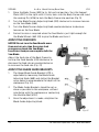
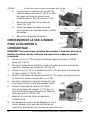
TOOL SET UP
1. Raise the Body Frame (#93) to its vertical position, and lock the Body
Frame in place with the Support Plate (#127) and Locking Pin (#126).
2. Open the Moveable Vise Plate (#38)
to accept the workpiece by rotating
the Hand Wheel (#31)
counterclockwise (Fig. 15).
3. Place the workpiece on the Machine
Bed (#122). Support the end if the
workpiece is long.
4. Clamp the workpiece firmly against the Mitre Vise Plate (#41) with the
Moveable Vise Plate by rotating the Hand Wheel clockwise.
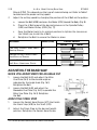
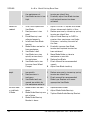
ADJUSTING THE
CUTTING SPEED
1. The Band Saw cuts at three different speeds: 80, 120, and 200 Feet per
Fig. 14
Fig. 15

V1.0 4 x 6 in. Metal Cutting Band Saw 9113465
Visit www.princessauto.com for more information 17
Minute (FPM). This depends on the type of material being cut. Refer to Table 1
to determine the proper cutting speed.
2. Adjust the cutting speed by changing the position of the V-Belt on the pulleys:
a. Loosen the Bolt (#108) and press the Motor (#115) toward the Body (Fig. 8).
b. Place the V-Belt around the desired grooves in the Spindle Pulley
(#99) and Motor Pulley (#105 [Fig. 7]).
c. Ease the Motor back to its original position to tighten the tension on
the V-Belt (see Install the V-Belt).
d. Retighten the Bolt to secure the Motor in place.
MATERIAL SPEED (FPM) PULLEY GROOVE
Spindle Motor
Tool Steel, Stainless Alloy Steels,
Bearing Bronze
80
Medium to High Carbon Steels,
Hard Brass or Bronze
120
Low to Medium Carbon Steels,
Soft Brass, Aluminum, Plastic
200
Table 1
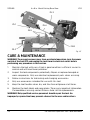
ADJUSTING THE BAND SAW
QUICK VISE ADJUSTMENT FOR AN ANGLE CUT
1. Loosen the Bolt (#43) and adjust the Mitre
Vise Plate (16-3) to the desired angle as
indicated by the Angle Scale (Fig. 16-1).
Retighten the Bolt.
2. Loosen the Bolt (#40) and adjust the
Moveable Vise Plate (Fig. 16-2) to parallel the
Mitre Vise Plate (Fig. 16-3). Retighten
the Bolt.
ADJUST THE STOCK STOP
1. Loosen the Socket Head Screw (#17) that holds
the Stock Stop (#18) to the Shaft (#19).
2. Adjust the Stock Stop to the desired length
position. Retighten the Socket Head Screw.
16
-1
16
-3
16
-2
Fig. 16
Fig. 17

9113465 4 x 6 in. Metal Cutting Band Saw V1.0
18 For technical questions call 1-800-665-8685
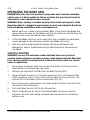
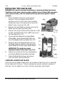
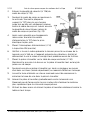
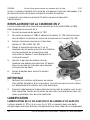
ADJUST THE BLADE GUIDE BEARINGS
A crooked cut may be the result of misaligned blade guides or uneven wear on
the Saw Blade (#66). Install and test a new saw blade to eliminate a dull blade
as the cause of the problem, before adjusting the Blade Guide Bearings (#72).
1. Check that the Blade Guide Bracket
Seats (#67, 74) are clear of the Saw Blade.
There should be from 0.000 in. (just
touching) to 0.001 in. clearance between
the Saw Blade and Blade Guide
Bearings (Fig. 18).
2. Adjust the Outer Blade Guide
Bearings (Fig. 18-1) that are mounted to the
Eccentric Shafts (#76) by loosening the
nuts (#5) while holding the Blade
Guide Bearings.
3. Turn the Outer Blade Guide Bearings
gradually until they are clear of the Blade.
Then retighten the Nuts.
4. Adjust the Inner
Blade Guide Bearings (Fig. 18-2) by loosening the
Bolts (#70) holding the Blade Guide Brackets (#73, 79) in place. Move the
Blade Guide Brackets forward or back until the proper clearance is
obtained. Retighten the Bolts.
ADJUST THE BLADE TRACKING
DANGER! When the tool is in operation, keep hands away from the saw blade
and the area it is being applied to. Failure to follow this warning will result in
amputation, serious personal injury or death.
IMPORTANT! The Blade Guide Bearings should be completely clear of the Saw
Blade if adjustment is necessary (see Adjust the Blade Guide Bearings).
This procedure requires running the Band Saw with the Blade Back Cover open.
Fig. 18
18-1
18
-2

V1.0 4 x 6 in. Metal Cutting Band Saw 9113465
Visit www.princessauto.com for more information 19
1. Adjust the Band Saw speed to its slowest
setting (see Adjusting the Cutting Speed).
2. Remove the Locking Pin (#126) from the
Body Frame (#93).
3. Raise the Body Frame to its full vertical
position. Turn the Support Plate (#127)
clockwise until it firmly locks into the
Body Frame and insert the Locking Pin to
lock Body Frame into position (Fig. 9).
4. Remove the Screw (#142) and Flat
Washer (#141) to open the Blade Back
Cover (#82). Turn on the Band Saw and
examine the Upper Blade Wheel (#83).
5. The Saw Blade (#66) is tracking properly
when the back of the Blade is just touching
the edge of the Upper Blade Wheel Flange
(Fig. 19-1). The back of the Blade should not
rub against the flange.
6. Turn off the Band Saw and loosen two
Bolts (#13) to a point where they are loose,
then tighten until snug (Fig. 20).
7. Restart the band saw and turn the Set Screw
(#96) until the Saw Blade tracks properly.
Make sure Blade tension is maintained by
turning the Blade Tension Adjusting
Knob (#91).
8. Turn off the Band Saw and retighten the two Bolts, when the adjustment
is complete.
9. Close the Blade Back Cover and secure with the Screw and Flat Washer.
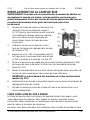
ADJUST THE BLADE TENSION
NOTICE! Release the blade tension when the Band Saw will not be used
for extended periods of time. This will prevent damage to the blade and
saw mechanism.
Fig. 19
19
-1
Fig. 20

9113465 4 x 6 in. Metal Cutting Band Saw V1.0
20 For technical questions call 1-800-665-8685
1. Raise the Body Frame (#93) to its full vertical position. Turn the Support
Plate (#127) to the right until it firmly locks into the Body Frame and insert
the Locking Pin (#126) to lock the Body Frame into position (Fig. 9).
2. Turn the Blade Tension Adjusting Knob (#91) clockwise to increase tension
on the Saw Blade (#66).
3. Turn the Blade Tension Adjusting Knob counterclockwise to decrease
tension on the Saw Blade.
4. Correct tension is acquired when the Saw Blade is just tight enough for
the Blade Wheels (#63, 83) to grip the Blade and turn it.
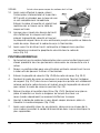
ADJUST THE FEED RATE
NOTICE! Do not turn the Feed Handle more
than one turn at a time. Excessive feed
pressure can break the Saw Blade.
Insufficient feed pressure rapidly dulls the
Saw Blade.
Adjust the feed rate of the Body Frame by
turning the Feed Handle (#35) clockwise to
decrease the feed rate or counterclockwise
to increase the feed rate (Fig. 21)
ADJUST THE BLADE GUIDE BRACKETS
1. The Upper Blade Guide Bracket (#79) is
adjustable by loosening the Blade Guide
Adjusting Knob (#68) and sliding the Bracket
up or down to accommodate the depth of the
workpiece (Fig. 22).
2. The Blade Guide Brackets should be set as
close as possible to the workpiece, without
interfering with the workpiece or contacting
the Machine Bed (#122).
3. Once the adjustment is made, retighten the
Blade Guide Adjusting Knob.
Fig. 21
Fig. 22
La page est en cours de chargement...
La page est en cours de chargement...
La page est en cours de chargement...
La page est en cours de chargement...
La page est en cours de chargement...
La page est en cours de chargement...
La page est en cours de chargement...
La page est en cours de chargement...
La page est en cours de chargement...
La page est en cours de chargement...
La page est en cours de chargement...
La page est en cours de chargement...
La page est en cours de chargement...
La page est en cours de chargement...
La page est en cours de chargement...
La page est en cours de chargement...
La page est en cours de chargement...
La page est en cours de chargement...
La page est en cours de chargement...
La page est en cours de chargement...
La page est en cours de chargement...
La page est en cours de chargement...
La page est en cours de chargement...
La page est en cours de chargement...
La page est en cours de chargement...
La page est en cours de chargement...
La page est en cours de chargement...
La page est en cours de chargement...
La page est en cours de chargement...
La page est en cours de chargement...
La page est en cours de chargement...
La page est en cours de chargement...
La page est en cours de chargement...
La page est en cours de chargement...
La page est en cours de chargement...
La page est en cours de chargement...
La page est en cours de chargement...
La page est en cours de chargement...
La page est en cours de chargement...
La page est en cours de chargement...
La page est en cours de chargement...
La page est en cours de chargement...
La page est en cours de chargement...
La page est en cours de chargement...
La page est en cours de chargement...
La page est en cours de chargement...
La page est en cours de chargement...
La page est en cours de chargement...
La page est en cours de chargement...
La page est en cours de chargement...
La page est en cours de chargement...
La page est en cours de chargement...
La page est en cours de chargement...
La page est en cours de chargement...
La page est en cours de chargement...
La page est en cours de chargement...
-
 1
1
-
 2
2
-
 3
3
-
 4
4
-
 5
5
-
 6
6
-
 7
7
-
 8
8
-
 9
9
-
 10
10
-
 11
11
-
 12
12
-
 13
13
-
 14
14
-
 15
15
-
 16
16
-
 17
17
-
 18
18
-
 19
19
-
 20
20
-
 21
21
-
 22
22
-
 23
23
-
 24
24
-
 25
25
-
 26
26
-
 27
27
-
 28
28
-
 29
29
-
 30
30
-
 31
31
-
 32
32
-
 33
33
-
 34
34
-
 35
35
-
 36
36
-
 37
37
-
 38
38
-
 39
39
-
 40
40
-
 41
41
-
 42
42
-
 43
43
-
 44
44
-
 45
45
-
 46
46
-
 47
47
-
 48
48
-
 49
49
-
 50
50
-
 51
51
-
 52
52
-
 53
53
-
 54
54
-
 55
55
-
 56
56
-
 57
57
-
 58
58
-
 59
59
-
 60
60
-
 61
61
-
 62
62
-
 63
63
-
 64
64
-
 65
65
-
 66
66
-
 67
67
-
 68
68
-
 69
69
-
 70
70
-
 71
71
-
 72
72
-
 73
73
-
 74
74
-
 75
75
-
 76
76


Powerfist 9113465 Le manuel du propriétaire
- Taper
- Le manuel du propriétaire
dans d''autres langues
- English: Powerfist 9113465 Owner's manual
